
Gear Rack
From tooth geometry and material grades to drive selection and installation — a practical reference for engineers, procurement teams, and system integrators sourcing precision rack-and-pinion components worldwide.
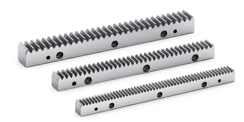
Unlimited Travel Length
End-butt multiple bars to extend any axis without size constraints.
High Force Density
Large-module racks transmit thousands of Nm of tangential force in a compact cross-section.
Precision Grades Available
From DIN8 general-industry to DIN5 ground-tooth precision — same product family, different finishing operations.
Gear Rack Types
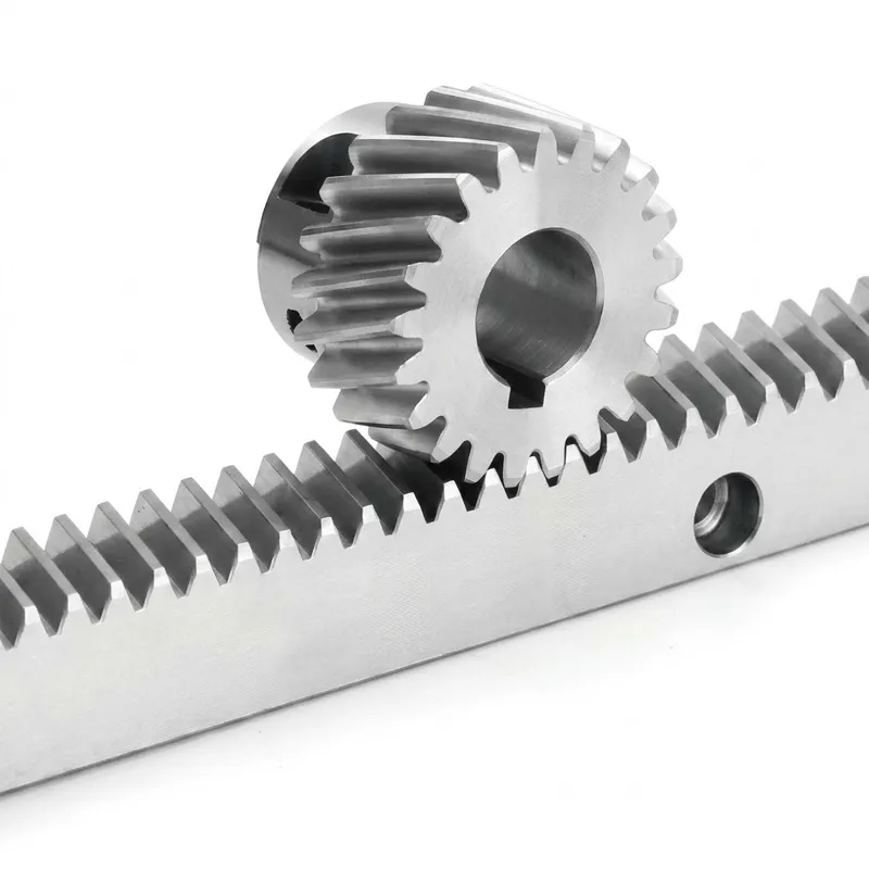
Helical Gear Rack
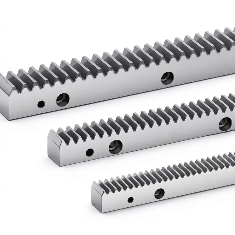
Straight Gear Rack
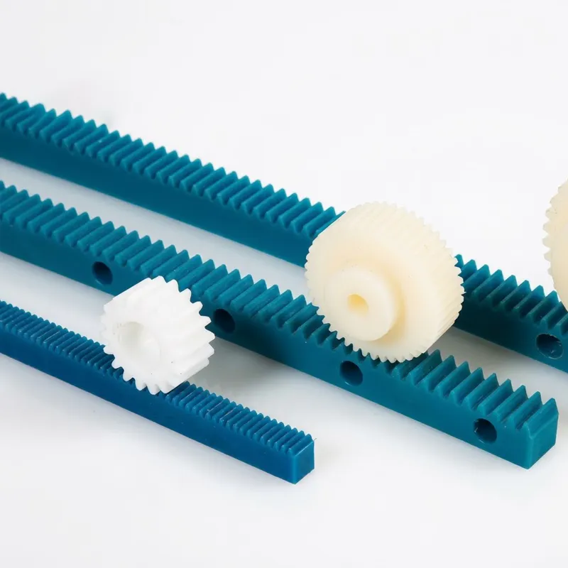
Plastic Gear Rack
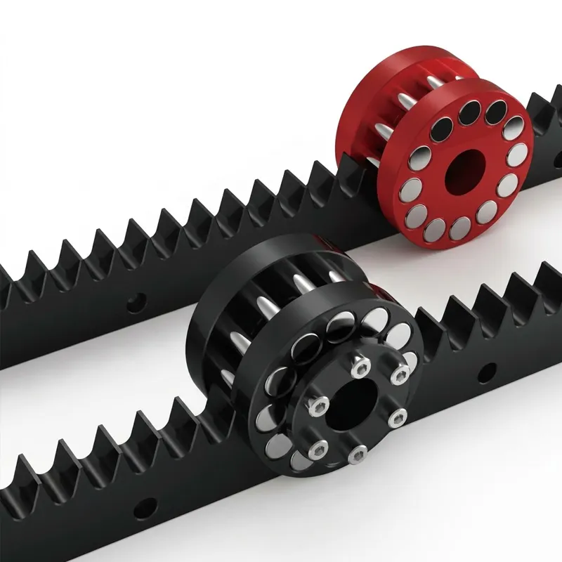
Zero-Backlash Gear Rack

V-Type Ground Helical Gear Rack

V-Type Ground Straight Gear Rack
Straight Gear Rack
• Straight (spur) tooth profile • Module M1.5 to M12 • Lengths 500 mm – 1,000 mm standard • Custom lengths available
Standard Grade
S45C material, quenching and tempering HB20–25°. Four-side flat grinding, fine cutting production process. General-purpose straight rack for industrial drives.
High-Frequency Hardened
S45C material, high-frequency quenching HRC48–52°. Four-side flat grinding, surface blackening or phosphating. Extended tooth life under cyclic loading.
Precision Ground
S45C / 42CrMo material, high-frequency quenching HRC48–52°. Four-side flat grinding after hardening, then tooth surface grinding. Sub-0.05 mm pitch error per metre.
Helical Gear Rack
• Helical tooth profile • Right helix angle 19°31'42" • Module M1.5 to M12 • Lengths 500 mm – 1,000 mm standard
Standard Helical
S45C, quenching and tempering HB20–25°. Four-side flat grinding, fine cutting. The entry-level helical rack for mid-speed drives where cost and noise performance must both be satisfied.
HF-Hardened Helical
S45C, high-frequency quenching HRC48–52°. Four-side flat grinding, surface blackening or phosphating. Higher tooth surface durability for demanding duty cycles.
Precision Ground Helical
S45C / 42CrMo, HF quenching HRC48–52° / carburising HRC50–55°. Four-side + tooth surface grinding. The highest accuracy grade for servo-driven precision axes in European and Japanese OEM machine tools.
V-Type Ground Guide Rack
• Straight or helical tooth • Integrated V-rail guidance • Module 1.59 – 3.18 (standard) • Lengths 630 / 930 / 1,230 mm • DIN6e25 • GTF/1000 < 0.036 mm
V-Type Straight Guide Rack
S45C / 42CrMo. HF quenching HRC48–52°; V-rail surface hardness HRC50–52° (S45C) or HRC55–60° (42CrMo). Four-side grinding, tooth surface grinding, V-rail surface grinding. No axial thrust from the straight tooth profile.
V-Type Helical Guide Rack
S45C / 42CrMo. Right helix 19°31'42". HF quenching HRC48–52°; carburising HRC55–60°. Four-side grinding, tooth surface grinding, V-rail surface grinding. Combines helical smoothness with integrated V-rail guidance.
Zero-Backlash Rack
• Straight tooth profile • Module M16 / M20 / M25 (large-module) • Black chromium surface plating • HRC48–52°
Engineered to work with preloaded pinion assemblies that eliminate the reversal dead band entirely. Four-side surface grinding after induction quenching restores pitch geometry to zero-backlash-compatible tolerances. Black chromium plating reduces friction at the preloaded tooth contact zone, enabling higher preload force without excessive power loss. The large-module range (M16–M25) makes this the only series in the catalogue specifically designed for heavy portal bridges, press tables, and structural welding gantries where standard-module racks would be undersized.
Plastic Gear Rack
• POM and nylon (PA) grades • Pitch-compatible with steel series • No lubrication required • Corrosion-free
Dimensionally interchangeable with the steel rack series — same tooth pitch geometry, same mounting hole patterns — so engineers can prototype with plastic and transition to steel for production without redesigning the drive geometry. POM (Delrin) provides better dimensional stability and lower friction; nylon PA absorbs shock better and tolerates moisture. Ideal for cleanroom automation, food processing conveyors, medical laboratory equipment, and light-duty office or consumer product mechanisms where metal contamination is unacceptable or where weight reduction outweighs the load capacity advantage of steel.
What Is a Gear Rack?
A gear rack is a flat or straight bar machined with a series of teeth along one face, designed to mesh with a circular pinion gear. When the pinion rotates, its teeth engage the rack teeth and push the rack in a straight line — or, if the rack is fixed, drive the pinion carriage along it. This rotary-to-linear conversion is the core principle behind every rack-and-pinion system, from a simple drill press column to a multi-axis CNC gantry spanning several metres.
Unlike a ball screw, a gear rack is theoretically unlimited in travel length — additional bars can be butted end-to-end to extend the axis without mechanical joints that degrade accuracy. Unlike a belt drive, it transmits high tangential force without slip and tolerates lateral loads from cutting tools or carriage weight. The trade-off is that a rack-and-pinion system requires lubrication management and, in precision applications, backlash control through preloaded pinion assemblies or tight-tolerance ground rack stock.
The key parameters that define a gear rack's performance are: module (the ratio of pitch diameter to tooth count, controlling tooth size and load capacity), tooth profile (straight/spur versus helical), material and hardness, accuracy grade (DIN or equivalent), and surface finish or treatment. Understanding how these interact is the foundation of correct rack selection.
Straight Tooth vs. Helical Tooth — What's the Difference?
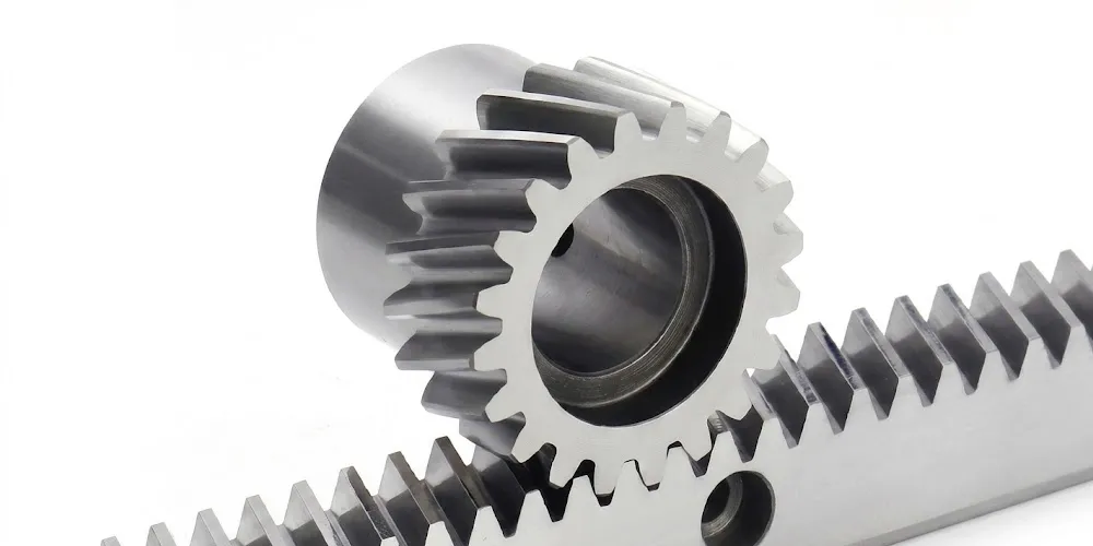
Straight (Spur) Tooth
Teeth are cut parallel to the rack axis. Every tooth engages the full face width simultaneously, creating a brief impact load at each pitch point. Simple to manufacture, generates no axial thrust force, and is the most cost-effective option for general-purpose, lower-speed, or moderate-load linear drives.
Best for: drill press columns, storage shelving actuators, door operators, agricultural equipment, and any application where simplicity and cost matter more than noise or peak smoothness.
Pressure angle: 20° standard | Available hardness: soft / induction-hardened / quenched & tempered
Helical Tooth
Teeth are cut at an angle (typically 19°31′42″ right helix) relative to the rack axis. The angled profile means each tooth enters mesh progressively across the face width, spreading the load over time and reducing the impulse force per pitch event. The result is quieter operation, higher permissible tangential loads per unit face width, and smoother motion at higher traverse speeds.
Best for: CNC machining centres, gantry robots, laser cutting machines, semiconductor handling, and precision axes where noise and vibration levels affect the process or the product.
Note: helical racks produce an axial thrust force that the bearing arrangement must absorb.
V-Type Integrated Guide Rack
A specialised straight-tooth variant with precision V-grooves machined along the rack body. The V-profile mates with V-rollers on the carriage, providing lateral and vertical constraint within the same component that drives the axis. This consolidation eliminates the alignment offset that exists whenever a separate guide rail and rack are mounted in parallel.
Best for: precision grinding machine tables, coordinate measuring machines, laser cutting axes, and any application requiring the smallest possible geometric offset between drive and guidance.
Total pitch error GTF/1000 < 0.036 mm | Accuracy: DIN6e25
ISO 9001:2015 Certified · 10+ Years Manufacturing Experience
Ready to Specify Your Gear Rack?
ISO 9001:2015
Quality Management Certified
DIN5 → DIN8
Full Accuracy Grade Range
Module M1.5 – M25
Widest Standard Range
Custom Ready
Non-standard sizes on drawing
Installation Guidance
To join two rack bars end-to-end with correct pitch continuity at the joint, standard racks are machined with half-tooth root forms on both end faces. These half-teeth mesh with the half-tooth end face of the adjacent bar to create one complete tooth at the joint — so there is no pitch discontinuity as the pinion travels across the junction. For helical racks, a reverse-direction tooth gauge is used to confirm that the helix correctly continues across the joint before final fastening.
Installation sequence: first, fasten the side mounting holes of each rack face to the sub-base, aligning tooth pitch using a tooth-pitch gauge. Then tighten the position lock pins on both end faces to complete the joint. Confirm mesh depth with a feeler gauge at multiple points along the rack length before running under load for the first time.
Step 1 — Mount Side Holes
Fasten the rack's side mounting holes to the base plate first. This is the primary alignment reference.
Step 2 — Set Tooth Pitch at Joint
Use a tooth-pitch gauge (reverse direction for helical) to verify correct pitch continuity between bars before tightening.
Step 3 — Lock Position Pins
Tighten the fixing pin holes on both end faces of the joined bars to complete the installation.
Material Reference
Material and Hardness Comparison
The following table summarises the key material and treatment options across the gear rack range, with the permissible rolling load σH and bending load σF values used in drive sizing calculations.
| Material / Treatment | Surface Hardness | σH (N/mm²) | σF (N/mm²) | Typical Use |
|---|---|---|---|---|
| C45 · soft | ~200 HB | 440 | 550 | Low-duty, low-speed, prototyping |
| C45 · induction hardened | HRC48–52° | 750 | 1,250 | General industrial automation — most common selection |
| 16MnCr5 · case hardened | HRC58–62° | 920 | 1,500 | High-speed precision, European OEM machine tool standard |
| 42CrMo4V · quenched & tempered | HRC50–55° | 600 | 730 | Heavy load, shock load, large-module structural applications |
Application factor 1.0; single tooth contact safety factor 1.0; tooth root stress safety factor 1.4; service life 20,000 h; speed 1.5 m/s.
Selection Guide
How to Choose the Right Gear Rack
Rack selection is a five-step process. Work through each decision in order — earlier choices constrain later ones, so shortcuts lead to undersized or overspecified components.
Module Quick-Reference: Approximate Permissible Tangential Force (C45 ind. hardened, straight tooth, b = 25 mm, v = 1.5 m/s)
| Module | M1.5 | M2 | M3 | M4 | M5 | M6 | M8 | M10 |
|---|---|---|---|---|---|---|---|---|
| Approx. Fu (N) | 45 | 95 | 256 | 450 | 750 | 1,070 | 1,900 | 3,400 |
| Tooth height (mm) | 3.4 | 4.5 | 6.8 | 9.0 | 11.3 | 13.5 | 18.0 | 22.5 |
Values are indicative; refer to the full selection tables in the product catalogue for exact permissible torques across all pinion tooth counts and face widths. Application factor = 1.0; service life = 20,000 h.