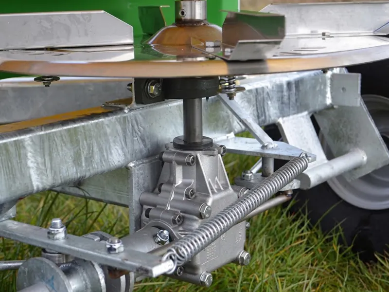
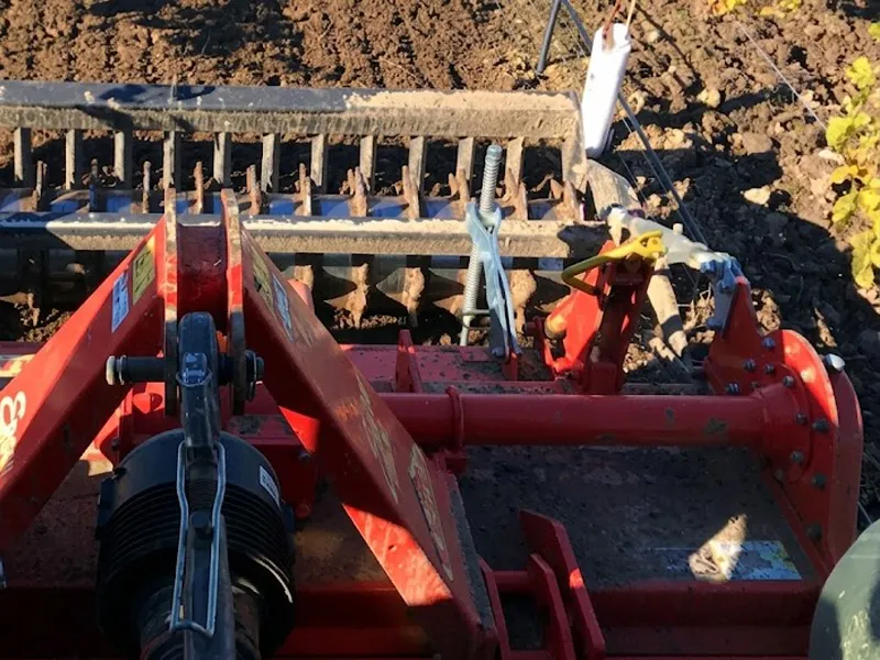
Agricultural Gearbox
From PTO-driven field implements to heavy-duty harvesting machinery — this essential drive unit converts tractor power into precise, reliable output across every season and soil type.
Introduction
What Is an Agricultural Gearbox?
An agricultural gearbox is a mechanical power transmission device designed specifically for use in farming machinery, converting the rotational output from a tractor's power take-off (PTO) shaft or engine into the precise torque, speed, and directional output required by a specific implement or attachment. Every tractor-driven field machine — from a simple rotary mower to a multi-row combine harvester header — depends on this drive unit to translate raw engine power into controlled, implement-specific mechanical work.
Unlike general-purpose industrial gearboxes, this class of drive unit is engineered to withstand the unique operating conditions of field use: shock loading from sudden blade contact with buried stones, wide thermal cycling from cold morning starts to full-load summer cutting, constant exposure to dust, moisture, crop debris, and chemical fertiliser contact. These units must deliver reliable performance across all these conditions without requiring workshop-level maintenance between seasonal overhauls.
Across modern farming operations — from the grain belts of North America and Australia to the mixed arable and livestock farms of Western Europe — the agricultural gearbox is a foundational component. Selecting the correct gearbox type, power rating, and gear ratio for the application determines whether an implement performs at its potential or becomes a persistent maintenance liability throughout the working season.
Agricultural Gearbox Types
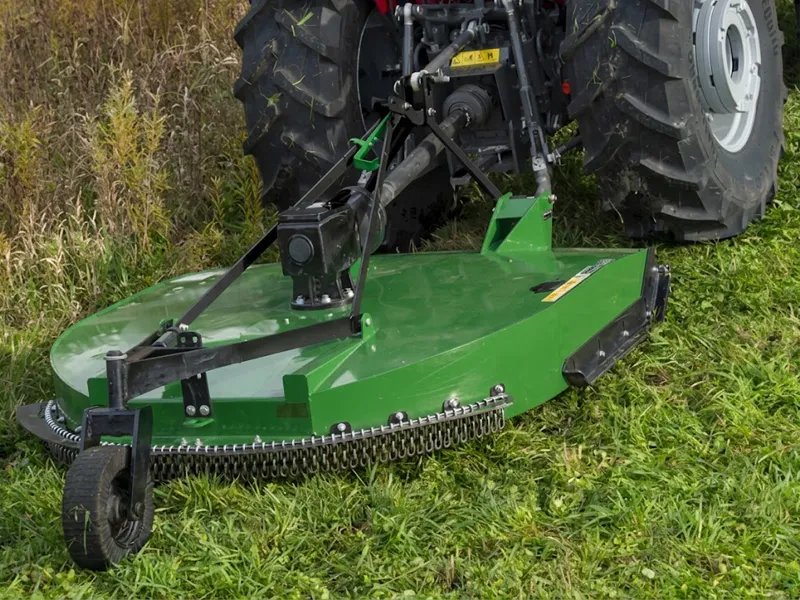
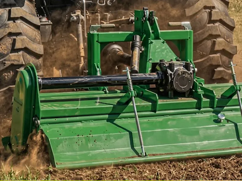
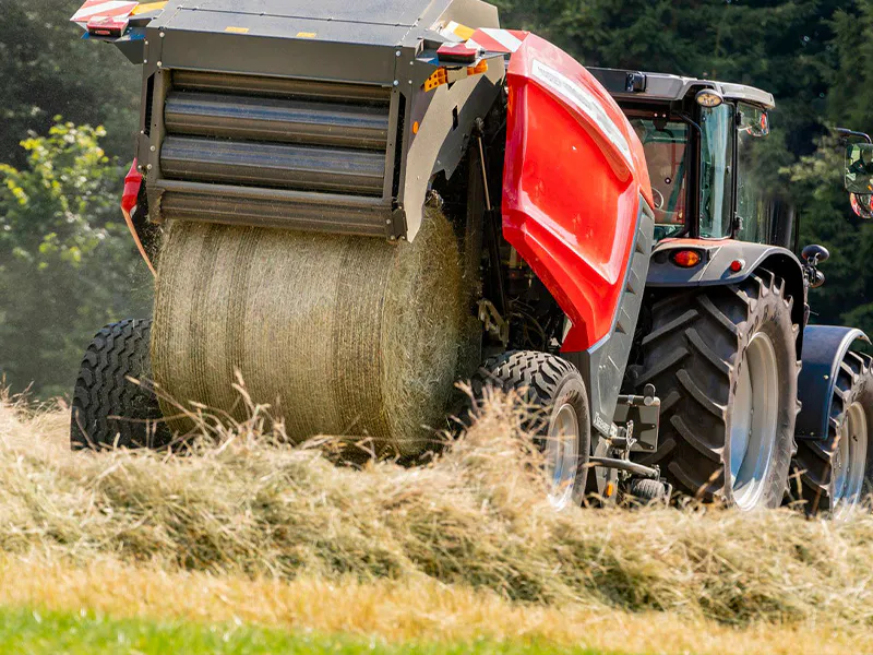
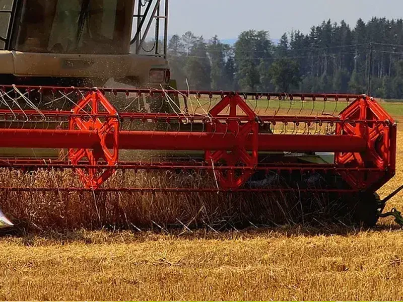
Our product range spans every major implement category and power class, from compact orchard mowers through to high-power combine headers and forage harvesters.
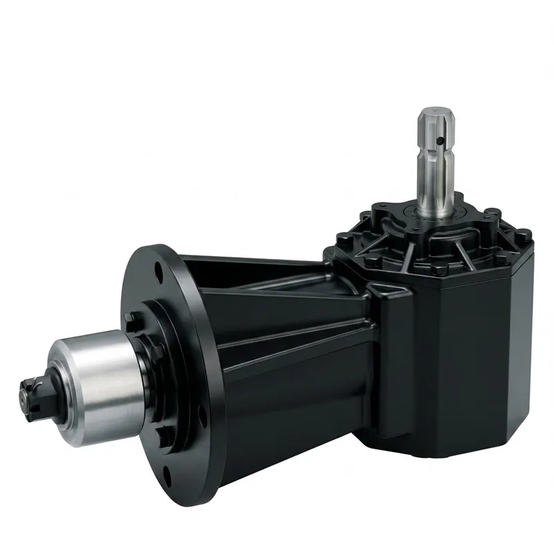
Lawn Mower Gearbox
WORKING PRINCIPLE
How Does an Agricultural Gearbox Work?
The fundamental principle is the same across all designs — controlled gear mesh converts one shaft's rotational energy into another shaft's speed and torque at a defined ratio. Understanding the five stages of this process clarifies how this transmission unit matches tractor power to implement demand.
PTO Power Input
The tractor's PTO shaft delivers rotational power — typically at 540 rpm or 1,000 rpm — through a telescoping PTO driveshaft into the gearbox input stub. The input shaft spline (commonly 1 3/8 Z6 or 1 3/4 Z20) transfers torque without backlash.
Bevel Gear Mesh
Inside the cast iron or ductile iron housing, the input bevel gear engages the output bevel gear. The gear tooth ratio — e.g. 15 teeth driving 29 teeth — determines the speed increase or reduction at the output shaft.
Direction Change
In right-angle configurations, the 90-degree bevel gear mesh redirects power from the horizontal PTO driveline to a vertical output shaft, which drives the blade hub, rotor, or implement working element directly below.
Oil-Bath Lubrication
All gear meshes and shaft bearings run submerged in or splash-lubricated by GL-4 or GL-5 gear oil. The sealed oil bath maintains a consistent lubricant film on every tooth contact surface throughout the working shift.
Implement Drive Output
The output shaft — plain bore, splined, or taper spline — drives the mower blade hub, tiller rotor, baler flywheel, or other working component at the design rpm and torque. Double-lip oil seals prevent lubricant loss and contaminant ingress.
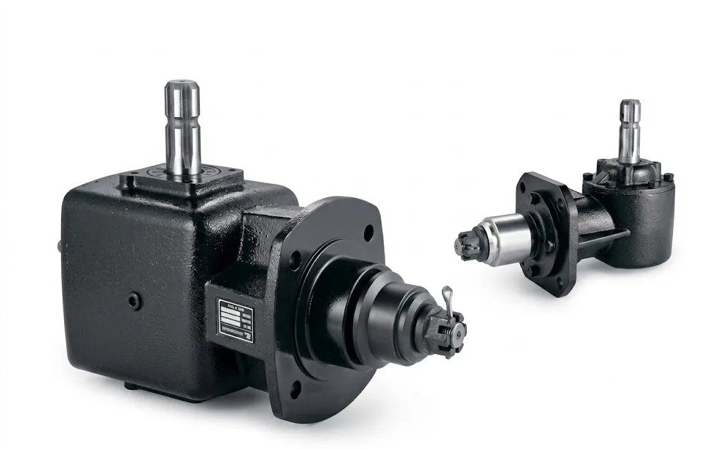
Applications of Forklift Hydraulic Cylinders
This transmission component appears in virtually every category of tractor-driven field equipment. The following scenarios represent the most common deployment contexts across global farming and land management operations.