
Mining & Quarrying · Application Guide
A technical reference for engineers and procurement teams specifying worm gear single speed reducers in underground coal, hard-rock, and mineral mining environments across Australia, North America, South Africa, and Europe.
Underground mine conveyor belts are among the most mechanically demanding continuous-duty applications that a single speed reducer is ever asked to serve. The drive train must start under full load, sustain months of uninterrupted operation in atmospheres laden with coal dust or silica particulate, tolerate ambient temperatures that swing from near-freezing in deep intake airways to elevated levels near exhaust headings, and do all of this in a space envelope constrained by roadway width and roof clearance. Specifying the wrong single stage speed reducer results not in marginal underperformance but in catastrophic failure — a blocked conveyor in a producing mine face has an immediate and measurable cost per hour.
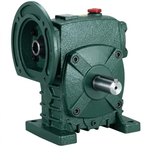
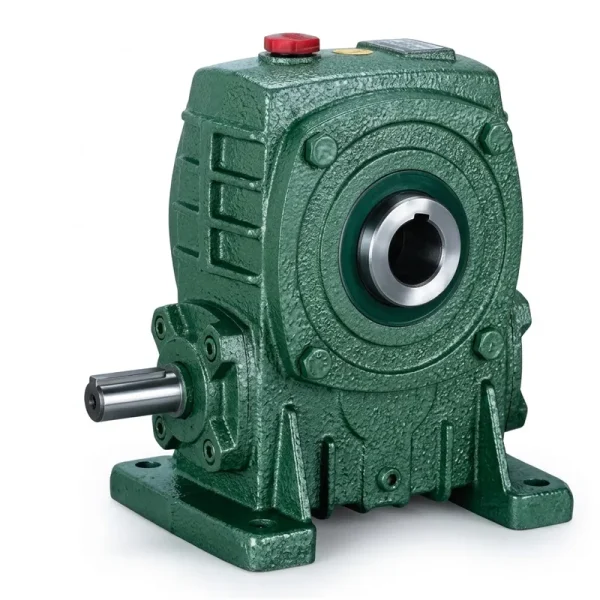
This guide covers the mechanical selection criteria, construction requirements, material standards, installation considerations, and lubrication regimes that determine whether a worm gear reducer performs reliably across its full service life in an underground conveyor application. It also identifies the EP-WPDS and EP-WPKA series products from the single-speed reducer range as reference designs that address the most common underground mine conveyor drive specifications.
Why Single-Stage Reduction Is the Standard for Underground Belt Conveyors
Most underground mine belt conveyors operate at belt speeds between 1.5 m/s and 4.5 m/s, driven by motors running at 960–1480 RPM. The output shaft of the drive pulley turns at 30–120 RPM depending on pulley diameter and belt speed. A single speed reduction stage with a reduction ratio in the range of 10:1 to 40:1 bridges this gap in one step, which is both mechanically simpler and more space-efficient than a two-stage arrangement. In an underground roadway where every cubic metre of excavated space has a capital and ongoing ventilation cost, the compact envelope of a single reduction worm reducer is a genuine engineering advantage over multi-stage inline alternatives.
The self-locking property of a worm gear drive — where the worm can drive the wheel but the wheel cannot back-drive the worm at reduction ratios above approximately 20:1 — is also a valuable inherent safety feature in conveyor applications. On inclined conveyors carrying ore or coal uphill, a self-locking single speed worm gear reducer prevents the loaded belt from running backwards on power loss, reducing dependence on external backstop devices. This characteristic does not eliminate the need for a positive mechanical backstop on high-power or steeply inclined conveyors, but it provides a secondary restraint that improves overall system safety in underground environments where uncontrolled reverse running would pose a serious hazard to personnel and equipment.

Manufacturing Structure of a Single Speed Reducer
А single speed worm reducer consists of five principal structural elements: the worm shaft, the worm wheel, the housing, the input and output bearings, and the oil-retaining sealing system. In the WP-series products commonly specified for underground conveyor drives, the worm shaft is an integral forging — the worm thread and shaft journals are machined from a single steel billet rather than being assembled from separate components. This eliminates a press-fit interface that could migrate under cyclic loading, ensuring the drive geometry remains constant across the full service life.
The worm wheel is a composite construction: the wheel hub and spoke structure is cast from ductile iron or cast steel, while the tooth ring — the portion that contacts the worm — is a separate bronze or high-tin-bronze annulus that is pressure-cast or shrink-fitted onto the hub. Composite wheel construction allows the more expensive copper alloy to be concentrated where it is needed (at the contact surface) while the less costly ferrous material provides structural bulk and inertia. The housing is a box casting machined in a single datum setup to ensure the bore centrelines of the worm shaft and worm wheel are accurately perpendicular and at the correct centre distance — errors in this geometry cause uneven load distribution across the tooth face and premature wear.
Material System
The worm thread form is hobbed on low-alloy steel (typically 20CrMnTi or equivalent) and case-carburised to achieve a surface hardness of HRC 58–62. After hardening, the thread flanks are precision-ground to achieve the tooth profile accuracy and surface finish (Ra 0.4–0.8 µm) needed for the hydrodynamic oil film to form between worm and wheel under load.
The tooth ring is cast from ZCuSn10Pb1 (approximately equivalent to BS1400 PB1 or ASTM B505 C90700) — a high-tin phosphor bronze chosen for its low coefficient of friction against hardened steel, good conformability that allows the tooth surface to wear-in uniformly during the bedding period, and acceptable strength for the contact pressures encountered in medium-duty conveyor drives.
Smaller frame sizes (centre distance up to approximately 100 mm) are commonly housed in pressure-die-cast aluminium alloy for weight reduction. Larger frame sizes carry ductile iron (GGG50 / ASTM A536 Grade 65-45-12) housings for the stiffness needed to maintain bearing bore alignment under the radial and axial loads generated by the worm drive reaction forces. Both materials are finished with a chemical-resistant paint system for underground use.
Reference Selection Table — WP-Series Single Speed Reducers for Underground Conveyors
The table below provides reference selection data for common underground mine conveyor drive configurations using WP-series worm gear speed reducers. All values are indicative; definitive selection requires calculating the service factor for the specific start frequency, load profile, and ambient temperature of each installation.
| Series | Input Power Range | Reduction Ratio | Output Torque | Typical Conveyor Role |
|---|---|---|---|---|
| EP-WPDS | 0.12 – 15 kW | 10:1 – 60:1 | Up to ~1800 N·m | Face conveyor auxiliaries, belt feeders, transfer conveyors |
| EP-WPKA | Up to 5 – 260 kg rated | 10:1 – 60:1 | Medium-high torque | Main gate conveyor drives, trunk belt head drives |
| EP-WPKS | Up to 4 – 365 kg rated | 10:1 – 60:1 | High output torque | Heavy-duty trunk belts, inclined ore conveyors |
| EP-WPDKA | Up to 5 – 350 kg rated | 10:1 – 60:1 | High torque, dual-input | Long-wall face end drives, multi-motor conveyor stations |
Recommended Products for Underground Conveyor Drives

Service Factor Application and Selection Criteria
Selecting a worm gear speed reducer for an underground conveyor requires applying a service factor to the motor rated power before matching against the reducer’s rated capacity. The base service factor for a belt conveyor with a squirrel-cage induction motor and no more than two starts per hour is typically 1.25–1.5 from standard catalogues (AGMA 6034, ISO 9283). In underground mining, additional derating applies for the following conditions:
Face conveyors and transfer points that start and stop with the mining cycle — sometimes 6–10 starts per shift — require a service factor addition of 0.25–0.5 above the base value. Each start imposes a torque spike of 2–3× rated torque on the reducer for the first 2–4 seconds of acceleration.
Worm gear efficiency is temperature-sensitive: as ambient temperature rises above 40 °C (typical in deep underground workings), oil viscosity falls, reducing film thickness and increasing sliding contact losses. Reducers in high-temperature headings should be specified one frame size larger than the base calculation would indicate to maintain safe oil-film temperature margins.
Inclined conveyors carrying ore or coal uphill impose a continuous gravity component on the drive that increases the steady-state torque demand above the level calculated for a horizontal belt of the same length and capacity. For inclinations above 12°, the steady-state torque increase must be calculated and added to the peak acceleration torque before applying the service factor.
Some underground conveyor installations require the single speed gear reducer to be mounted with the output shaft vertical (horizontal shaft reducer tilted 90°) or at an intermediate angle to suit the roadway geometry. Non-horizontal mounting affects the oil level within the housing and must be communicated to the supplier at the specification stage so the oil capacity and filler/drain positions can be adjusted accordingly.
Lubrication Requirements for Underground Environments
The lubricant is the single most consequential maintenance variable in a worm gear reducer installation. Worm gear contact is predominantly sliding rather than rolling — the relative velocity between worm flank and wheel tooth is high, and the lubricant film is the only thing separating the two surfaces. The correct lubricant for a single speed worm gear reducer in underground mine service is a AGMA 7 or 8 (ISO VG 460 or ISO VG 680) extreme-pressure gear oil with anti-wear additives and a phosphor-bronze compatibility certification — not all EP additives are compatible with the bronze wheel, and some sulphur-phosphorus additives attack tin bronze aggressively at elevated temperature.
In underground mines, the additional requirement is that the lubricant must be approved for use in a potentially methane-bearing atmosphere — in practice, this means the oil must have a flash point above 200 °C (closed-cup) and must not contain solvents or diluents that could contribute to an ignition hazard. Many surface-specification gear oils meet the AGMA viscosity grade and EP requirement but fail the underground flash-point criterion; the lubricant specification should be confirmed against the mine’s ventilation and electrical safety requirements before ordering. Oil changes at 2000–4000-hour intervals are typical for WP-series reducers in underground service, with oil condition monitoring (particle count and viscosity check) recommended at 1000-hour intervals in high-duty installations.
Installation, Alignment, and Commissioning
Correct installation of a single reduction worm gear unit on a mine conveyor drive begins with verifying that the support structure — whether a concrete plinth, a steel-channel base frame, or a fabricated conveyor drive frame — is level, planar, and of adequate stiffness to prevent deflection under the combined weight of motor, reducer, and drive pulley. A base frame that flexes under load will cause the reducer foot pads to distort the housing, introducing misalignment between the worm shaft and wheel centrelines that accelerates tooth wear and bearing failure.
For the hollow-shaft, torque-arm configuration of the EP-WPKA and EP-WPKS series, commissioning includes verifying that the torque arm rubber bush is in good condition, that the torque arm bolt can move freely in its slot (it must not be pinned or welded, as this would prevent the natural thermal expansion of the housing), and that the torque arm anchorage point on the conveyor structure is at the correct radial distance from the reducer output bore centreline. Incorrect torque arm geometry introduces secondary bending moments into the reducer housing that the designer did not account for and that can crack the housing or fail the output shaft bearing over time. Shaft alignment for coupled configurations should be within 0.05 mm parallel and 0.05°/100 mm angular before the coupling is fitted and the motor bolted down.

Condition Monitoring and Predictive Maintenance
Underground conveyor single speed reducer maintenance has shifted progressively from fixed-interval replacement to condition-based intervention in most modern mining operations. The principal condition indicators for a worm gear reducer are worm shaft bearing vibration (measured by accelerometer at the input bearing housing), output bearing temperature (thermocouple or infrared), oil temperature (thermocouple in the sump), and oil particle count from periodic sampling. Early-stage worm wheel tooth wear produces bronze particles in the oil that are detectable at particle concentrations of 50–200 ppm before any vibration or temperature signal becomes apparent — making oil sampling the most sensitive early-warning tool available for this component type.
Vibration analysis on a worm reducer is less straightforward than on a parallel-shaft gearbox because the worm mesh frequency and its harmonics overlap with bearing defect frequencies in a way that is difficult to separate without detailed signal processing. Temperature monitoring is more reliable as a trend indicator: a rise in steady-state oil-sump temperature of more than 10 °C above the historical baseline (at the same load and ambient conditions) consistently indicates either increased internal friction from tooth wear, reduced oil viscosity from thermal degradation, or partial loss of oil from a seal leak. Underground mine maintenance teams in South Africa, Australia, and Canada have standardised on quarterly oil samples and monthly bearing temperature trending as the minimum condition monitoring regime for primary conveyor drive reducers.
Manufacturing Capability — Over a Decade of Gearbox Engineering
Our manufacturing facility has operated in mechanical power transmission for more than ten years, producing a wide range of drivetrain components for industrial, agricultural, and mining applications under ISO 9001:2015 quality management system certification. The product range covers agricultural gearboxes, worm gear reducers, planetary gear drives, power take-off shafts, hydraulic cylinders, precision gears, roller chains, and electric motors. Structural housings are produced in ductile iron, grey cast iron, cast steel, precision investment-cast steel, and aluminium alloy to match the specific load, environmental, and weight requirements of each product. Gears, sprockets, worm wheels, pulleys, worm shafts, and output shafts are machined on multi-axis CNC hobbing, grinding, and turning centres to DIN and ISO dimensional standards. Customers requiring a complete conveyor drive system — reducer, motor, coupling, and mounting hardware — can source through a single technically accountable manufacturing partner rather than coordinating across multiple vendors.
Шеберхана



Compatible Drive Components
A complete underground conveyor drive station requires more than the reducer alone. The following complementary product lines are available from the same supply source, allowing engineers to procure a fully matched, tested drive train rather than integrating components from separate vendors.


Жиі қойылатын сұрақтар
Редактор: PXY