
Packaging & Logistics · Automated Sortation
A technical guide for logistics engineers, automation integrators, and procurement managers in the United States, United Kingdom, Germany, Japan, and other markets operating high-throughput parcel and e-commerce fulfillment facilities.
Sortation Drive Systems and the Case for Single-Stage Worm Gearing
Automated sortation systems in parcel and e-commerce distribution centers operate around the clock during peak fulfillment periods, processing thousands of packages per hour across belt sorters, cross-belt carriers, tilt-tray units, divert conveyors, and pop-up wheel sorters. Each of these subsystems relies on a drive mechanism that converts motor speed to a lower, controlled output speed. The single speed reducer — specifically the single stage right-angle worm-gear speed reducer — is a standard solution for this role across all of these sorter types.
The appeal is straightforward: a right-angle output geometry that simplifies the spatial arrangement of motor and driven shaft, a compact housing that fits within the crowded undercarriage of sorter frames, a reduction ratio range of 1:10 to 1:60 in a single gear stage that covers the majority of sortation conveyor speed targets, and a self-locking characteristic at higher ratios that prevents back-driving when the sorter is stopped. For distribution centers where maintenance windows are short and replacement parts must be standardized across dozens or hundreds of drive points, the WP series single speed gear reducer offers a predictable, interchangeable platform.

Manufacturing Structure
The WP series single speed reducer is built on an integral one-piece cast-iron housing. Unlike split-body designs, the monolithic housing is bored and faced in a single CNC setup — this manufacturing approach sets the center distance between the input worm shaft and the output wheel shaft to a dimensional tolerance that directly governs the gear mesh quality. Tight center distance tolerance translates to even tooth load distribution across the bronze wheel face, reducing localized wear that would shorten the wheel’s service life in the continuous-duty cycles of a distribution center sortation system.
Both the input and output shafts are supported by precision rolling element bearings retained within machined bearing bores in the housing. This dual-supported shaft arrangement minimizes shaft deflection under radial loads — forces that arise from belt tension, chain pull, or divert arm reaction loads in sortation equipment. In cross-belt carrier drives, where the take-up tension on the small belt loop can generate significant radial loading on the output shaft, this structural rigidity protects bearing life across the extended runtime required of e-commerce fulfillment operations.
Housing fins are cast into the exterior of the WP series body to increase the effective surface area for convective heat dissipation. In the tight undercarriage of a belt sorter where airflow is restricted, this ribbed geometry provides additional thermal margin without adding external cooling devices. For sortation systems running three shifts, thermal equilibrium is reached within the first hour of operation; the housing surface temperature at steady state is the practical thermal limit that governs whether a given frame size is appropriate for the application.
Material System
Gray cast iron is the standard housing material across the WP series. Its combination of good machinability, inherent vibration damping, and dimensional stability under thermal cycling makes it well suited to sortation environments where the drive unit is subjected to repeated start-stop cycles, ambient temperature swings between air-conditioned facility zones and unheated dock areas, and the low-frequency mechanical vibration generated by package impacts on conveyor surfaces above the drive unit.
The worm is machined from case-hardened alloy steel — commonly 20CrMnTi — and the tooth profile is finish-ground after case hardening. The ground worm surface provides a controlled sliding contact with the bronze worm wheel and produces less heat per unit of torque transmitted than a non-ground alternative, which is relevant in applications where heat accumulation over long shifts is a concern. The worm wheel is cast from tin bronze or phosphor bronze, materials that exhibit controlled and predictable wear characteristics and a natural affinity for the mineral gear oils specified for WP series lubrication.
Input and output shafts are produced from medium-carbon steel with hardened journal surfaces where they run against the inner races of the rolling element bearings. The output shaft is machined with a standard keyway so that sprockets, timing pulleys, and coupling hubs used in sortation conveyor drives can be fitted without modification. For hollow-shaft configurations (EP-WPZ, EP-WPKZ), the bore is machined to H7 tolerance to accommodate a standard conveyor shaft in an interference or keyed fit, which is the preferred arrangement for pop-up wheel sorter and divert conveyor drives where a separate coupling adds undesirable axial length.
Recommended Model for Sortation System Drive Points
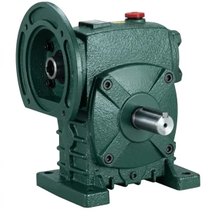
EP-WPDS — 0.12 to 15 kW Input Power Single Speed Reducer
The EP-WPDS is a foot-mounted, flange-input single stage speed reducer designed for continuous-duty drive applications. Its input flange accepts an IEC-standard motor directly on the reducer input face, and the output shaft exits horizontally from the opposite side of the housing — a geometry that suits belt sorter drives and divert conveyor drives where horizontal shaft alignment with the conveyor roller is the natural arrangement. The power range of 0.12 to 15 kW accommodates both small-footprint pop-up transfer units running sub-kilowatt motors and heavy-duty induction sorter lanes requiring full-frame motors up to 15 kW.
| Parameter | Value |
|---|---|
| Input Power Range | 0.12 – 15 kW |
| Input Speed | ≤ 1500 rpm |
| Reduction Ratio (Single Stage) | 1:10 – 1:60 |
| Mounting Type | Foot mounted / flange input |
| Housing Material | Cast iron (integral box) |
| Operating Ambient Temp. | -40°C to +40°C |
| Frame Sizes (center distance) | 40 – 250 mm |
Drive Mechanics Across Sortation System Types
Different sortation technologies impose distinct load and speed profiles on their drive systems. Belt sorters — where a flat or modular belt carries packages along a straight run and diverts them laterally at decision points — require a constant low-speed, high-torque output to move the fully loaded belt against friction, belt weight, and package mass. The output speed of a single speed reducer driving a belt sorter is typically in the 20–50 rpm range, achieved through a single reduction ratio of 1:30 to 1:60 from a standard 4-pole motor.
Cross-belt sorters, where individual carrier carts each carry a small transverse belt, require a separate drive at each carrier unit as well as a main track drive. The individual carrier belt drives use small, low-power reducers — often in the 0.12 to 0.75 kW input power range — and the compact dimensions of the WP series smallest frame sizes (40 mm and 50 mm center distance) allow these units to be integrated within the carrier body without extending beyond the standard cart envelope. The main track drive for the recirculating loop may use larger units in the 1.5 to 7.5 kW range depending on the facility throughput rate and loop length.
Pop-up wheel sorters use banks of small motorized transfer rollers that rise to redirect packages from the main conveyor onto lateral takeaway lanes. Each bank of wheels is typically driven by a single shaft with multiple rollers mounted on it, powered by a small reducer at one end. The hollow output shaft configuration of the EP-WPZ model is particularly well suited here, as the reducer body mounts directly onto the drive shaft of the roller bank, eliminating the need for a separate coupling or shaft extension and keeping the overall drive package width within the narrow confines of the sorter module.

Speed and Ratio Reference for Sortation Subsystems
The table maps common sortation subsystem drive points to their typical output shaft speed requirements and the corresponding single stage reduction ratio from a standard 4-pole motor. Values are indicative; final selection requires verification against the drive roller or shaft diameter and the specific package throughput rate.
| Sortation Subsystem | Output Speed (rpm) | Motor Input (rpm) | Ratio Range | Power Range |
|---|---|---|---|---|
| Belt sorter main drive | 20 – 50 | 1450 | 1:30 – 1:60 | 2.2 – 15 kW |
| Cross-belt carrier (per unit) | 60 – 150 | 1450 | 1:10 – 1:20 | 0.12 – 0.75 kW |
| Pop-up wheel sorter bank | 80 – 180 | 1450 | 1:10 – 1:15 | 0.12 – 0.55 kW |
| Divert conveyor (lateral takeaway) | 30 – 60 | 1450 | 1:25 – 1:50 | 0.37 – 2.2 kW |
| Accumulation buffer conveyor | 15 – 30 | 1450 | 1:50 – 1:60 | 0.55 – 3 kW |
| Induction conveyor (merge/align) | 40 – 80 | 1450 | 1:15 – 1:30 | 0.75 – 5.5 kW |
Hollow Shaft Configuration for Pop-Up and Roller-Bank Drives
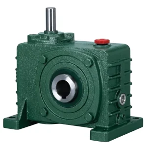
EP-WPKZ — 0.4 to 5.2 L Oil Capacity Single Speed Reducer
The EP-WPKZ combines a hollow output shaft with a motor flange input and is particularly effective for sortation applications where the reducer mounts directly onto the driven shaft — pop-up wheel sorter roller banks, narrow conveyor drives, and divert mechanism shafts in automated parcel handling systems. The hollow bore accepts the machine shaft in an interference or keyed arrangement, eliminating an external coupling joint that would otherwise increase the axial length of the drive package and create an additional alignment maintenance task in a dense sorter undercarriage.
| Parameter | Value |
|---|---|
| Oil Capacity Range | 0.4 – 5.2 L |
| Output Configuration | Hollow bore, keyed or shrink disc |
| Input Connection | IEC motor flange |
| Reduction Ratio | 1:10 – 1:60 |
| Frame Sizes | 40 – 250 mm center distance |

Operational Reliability in Peak-Season Distribution Center Conditions
E-commerce distribution centers in the United States, United Kingdom, and Germany experience dramatic throughput surges during peak periods — the fourth quarter in Western markets, national holiday shopping periods in Southeast Asia, and promotional sale events that can triple daily parcel volume over a two-week window. During these periods, sortation equipment typically runs at extended hours with reduced maintenance access. The single speed reducer’s value in this context is partly its performance and partly its predictability: a correctly specified unit running within its rated torque and thermal envelope has a failure mode that is gradual rather than sudden.
Early indicators of a worm wheel approaching its wear limit — a slight increase in output shaft backlash, a subtle change in operating temperature — are detectable through routine vibration monitoring or thermal imaging during scheduled maintenance windows. This allows planned replacement rather than emergency repair, which in a sortation system can mean the difference between a brief single-drive-point shutdown and a full line stoppage that impacts upstream and downstream operations across the entire distribution center. Standardizing on one single speed reducer platform across multiple drive points in the facility simplifies spare parts inventory and reduces the risk of incorrect replacement parts being fitted under time pressure.
Selection Criteria for Distribution Center Drive Engineers
Output Torque Demand
Calculate steady-state torque from belt or chain pull force multiplied by the drive roller radius. Apply a service factor of 1.25–1.5 for continuous-duty sortation drives that start under full load. This margin ensures the bronze worm wheel operates below the contact fatigue threshold over the expected multi-year service interval.
Required Output Speed
Determine from conveyor belt speed specification and drive roller circumference. Divide motor synchronous speed by the target output rpm to obtain the nominal ratio, then select the nearest standard catalogue ratio. Where a VFD is used for speed adjustment, confirm that the torque demand is within the reducer rating across the entire frequency range.
Shaft and Mounting Geometry
Match the output shaft orientation (horizontal, vertical) and the input shaft connection type (motor flange, solid input shaft, double input) to the machine layout. Specifying the wrong suffix in the model number requires a full physical repositioning of the motor that adds significant commissioning cost in a densely arranged sorter frame.
Thermal Environment
Distribution centers in the Middle East, South Asia, and equatorial regions often maintain ambient temperatures above 35°C in non-refrigerated zones. At these conditions, the natural convection thermal rating of the reducer is reduced. Specify the next frame size up, or select a synthetic gear oil with a higher viscosity index to maintain oil film thickness at elevated sump temperatures.
Standardization Across Drive Points
A facility with 200 conveyor drive points benefits from standardizing on two or three reducer frame sizes across all subsystems rather than specifying the exact minimum size for each. The cost of slightly oversized units is more than recovered through reduced spare parts inventory, faster maintenance crew familiarity, and the ability to carry one replacement unit that covers multiple positions.
VFD Integration
Modern automated sortation systems in facilities across Europe and North America increasingly use VFDs on sortation conveyor drives to allow throughput rate adjustment during off-peak periods and soft-start operation during line startup. The worm gear speed reducer requires no internal modification for VFD use; the motor must be inverter-duty rated and equipped with thermal protection for sustained low-frequency operation.
Compatible Drive System Components
The single speed reducer functions as one component within a complete drive system. The following products are manufactured to compatible dimensional and performance standards and are available from the same source for consolidated procurement:

Electric Motors
IEC-frame AC motors in B3, B5, and B14 configurations are dimensionally matched to the WP series flange-input reducers for direct face-to-face coupling. Motor frames are available in standard 2-pole and 4-pole configurations for 50 Hz and 60 Hz supply frequencies, covering the full input speed range of sortation drive applications from compact carrier belt drives through heavy main belt sorter drives. Inverter-duty windings support VFD-controlled sortation systems without additional motor derating.

Worm Gearbox
Sortation system drives that require output speeds below the range achievable from a single stage reducer — deep accumulation buffers, slow-speed pallet transfer shuttles, and multi-stage reduction configurations — are served by the full worm gearbox series, which includes universal, double-stage, and multi-stage configurations. Shared casting standards with the single stage units mean that seals, bearings, and oil fill plugs are interchangeable across both series, which simplifies the spare parts management task for distribution center maintenance teams.
Frequently Asked Questions
Editor: PXY