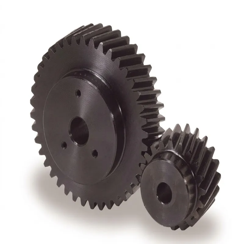
EP-Ground Helical Gear — Precision-Finished Helical Gear for Demanding Transmission Applications
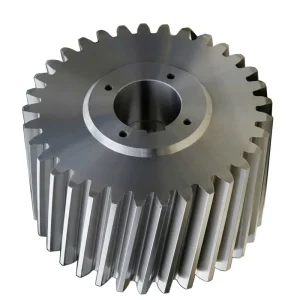
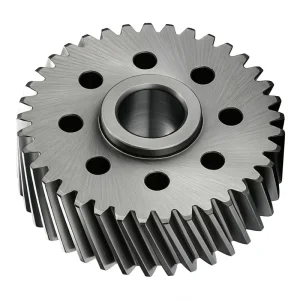
The EP-Ground Helical Gear (Module 1, 100 Tooth) is a high-precision transmission component designed for smooth and quiet operation. Featuring a left-hand helix with a 21°30′ helix angle and a standard 20° pressure angle, this S1 shape gear ensures efficient power transfer and reduced axial load stress. Manufactured with a ground bore (15.0 mm) for superior concentricity, it has a pitch diameter of 100.00 mm and an outer diameter of 102.00 mm. The gear includes a 50.0 mm hub diameter with a 10.0 mm hub width and an 8.0 mm face width, resulting in a compact total length of 18.00 mm. Ideal for precision machinery, robotics, and automation systems requiring accurate motion control and high durability.
EP-Ground Helical Gear — Precision-Finished Helical Gear for Demanding Transmission Applications
The EP-Ground Helical Gear series represents the upper tier of our helical gear product line — engineered for applications where surface accuracy, quiet operation, and load consistency are non-negotiable. Unlike standard hobbed gears, every tooth flank in this series is individually ground to tight tolerances, delivering measurably smoother engagement across the full mesh cycle. Whether you're sourcing for a CNC machining center, an automated packaging line, or a precision conveyor drive, this gear is built to perform where standard gears fall short.
Technical Specifications (Module 1, 100T, Left Hand)
| Параметр | Құндылық | Ескертпелер |
|---|---|---|
| Bore Type | Ground | H7 bore tolerance, finish-ground |
| Transverse Module | 1 | Standard metric module |
| Тістер саны | 100 | Full helical tooth set |
| Helix Direction | Left Hand | Right-hand versions available on request |
| Shape | S1 | Standard hub profile |
| Bore Diameter (A) | 15.0 mm | Ground bore, H7 fit |
| Hub Diameter (B) | 50.0 mm | Ground face, runout ≤ 0.01 mm |
| Pitch Diameter (C) | 100.00 mm | Transverse pitch diameter |
| Outer Diameter (D) | 102.00 mm | Tip circle diameter |
| Face Width (E) | 8.0 mm | Active tooth face |
| Hub Width (F) | 10.0 mm | Hub projection dimension |
| Total Length (G) | 18.00 mm | Overall axial length |
| Helix Angle | 21°30' | Transverse contact ratio enhanced |
| Pressure Angle | 20° | Standard involute tooth form |
| Quality Class | DIN 5 or better | Post-grinding inspection verified |
What Is a Ground Helical Gear — and How Does It Work?
A helical gear is a cylindrical gear whose teeth are cut at an angle — the helix angle — relative to the rotational axis. This angled tooth geometry means that, unlike straight-cut spur gears, multiple teeth enter mesh simultaneously rather than a single tooth pair making abrupt contact. The result is a gradual, rolling engagement that distributes load more evenly across the face width, dramatically reducing impact shock, vibration, and audible noise under load.
What distinguishes the EP-Ground variant from a standard hobbed helical gear is the final grinding operation. After hobbing, each gear blank goes through a precision tooth-grinding process that corrects any accumulated pitch error, profile deviation, and lead irregularity left by the cutting process. The ground tooth surface achieves a much tighter DIN or JIS quality class — typically DIN 5 or better — compared to a hobbed gear which commonly lands at DIN 7 to DIN 9. In practical terms, this means the meshing contact patch is more uniform across the entire tooth face, reducing localized stress concentrations that can cause pitting or fatigue spalling over time. For engineers asking how does a helical gear work at its best, the answer lies in the combination of the inherent helix geometry and the surface precision that tooth grinding provides.
The EP-Ground series operates on parallel shafts, with left-hand and right-hand versions available to accommodate opposing thrust requirements or matched-pair configurations. The ground tooth flank also improves lubricant film retention, further extending service life in continuous-duty industrial environments. If you have been comparing a helical gear vs spur gear for your drive train design, the helical type consistently wins on noise, load capacity per unit face width, and fatigue life — and the ground finish takes all three advantages a step further.
Five Key Advantages
Superior Tooth Surface Accuracy
Tooth grinding achieves DIN 5 or better quality class. Profile deviations and pitch errors are corrected after hobbing, providing a contact pattern that remains consistent across the full operating speed range — critical for precision indexing drives and helical gearbox types used in machine tools.
Low Noise, Smooth Power Delivery
The helix angle of 21°30' ensures gradual tooth engagement — multiple teeth share load at every instant. Combined with the ground finish, this eliminates the impact-impulse noise that plagues straight-cut or coarsely-finished gears, making this series a preferred choice for food processing and packaging machinery where quiet operation matters.
Higher Load Capacity Per Face Width
Are helical gears stronger than straight cut gears? Under equivalent module and face width conditions, yes — helical teeth develop a larger effective contact ratio, distributing transmitted torque across a greater surface area. The EP-Ground's precise tooth geometry maximises this advantage, allowing a compact gear to handle loads that would require a wider or larger-module spur gear.
Consistent Interchangeability Across the Series
With a standardised transverse module of 1, pressure angle of 20°, and S1 hub shape, the EP-Ground range integrates directly with our broader helical gear series — including matched pinion sets and helical rack and pinion configurations. Sourcing left-hand and right-hand pairs from a single series eliminates mismatched tolerance stack-ups that occur when mixing gears from different helical gear suppliers.
Extended Fatigue Life Through Optimised Surface Hardness
The ground tooth flanks are case-hardened to provide a hard, wear-resistant surface layer over a tough core. This combination resists pitting, micropitting, and scuffing — the primary failure modes in high-cycle gear applications. The result is a longer maintenance interval and lower total cost of ownership across the lifecycle of your helical gear shaft assembly.
Material & Construction
The EP-Ground series is produced from high-grade alloy structural steel — typically 20CrMnTi or 42CrMo4 equivalent — selected for its combined strength, machinability, and response to case-hardening heat treatment. The blank is first turned and bored to close dimensional tolerances before hobbing the tooth profile. Following heat treatment, the tooth flanks are precision-ground on CNC gear grinding machines, achieving a tooth surface roughness of Ra 0.4 µm or better.
The bore is finish-ground to H7 tolerance, ensuring a reliable interference or transition fit onto the mating shaft — eliminating fretting wear at the bore-shaft interface that is common with poorly-fitted gear assemblies. The hub faces are also finish-ground to maintain runout within 0.01 mm, which is essential for accurate positioning in indexing and precision conveyor drive applications.
For specific material certifications, hardness values, or material substitutions required by your project specification — particularly for food-grade, marine, or high-temperature environments — contact us directly for engineering support. Our team of mechanical transmission specialists has over a decade of experience working with international procurement and engineering teams across North America, Europe, and Southeast Asia.
Working Principle of the Helical Gear
Helical gears transmit rotary motion between parallel shafts through an involute tooth profile cut at a defined helix angle to the gear axis. As the driving gear rotates, the leading edge of each helical tooth begins meshing with its counterpart on the driven gear before the previous tooth pair fully disengages. This overlapping engagement — characterised by a total contact ratio greater than that of equivalent spur gears — is the fundamental reason helical gears operate more smoothly and carry more torque per unit of module.
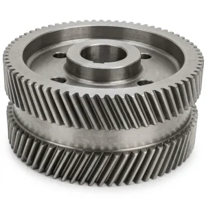
In the EP-Ground series, the 21°30' helix angle is chosen to optimise the overlap contact ratio while keeping the axial thrust force within a range manageable by standard angular-contact or tapered roller bearings. The axial thrust force generated by the helix angle is an important design consideration — it acts along the gear shaft axis and must be reacted by the shaft bearings. Engineers specifying these gears in new helical gearset or helical gear reducer designs should account for this thrust component in their bearing selection calculations. In many cases, paired left-hand and right-hand helical gears mounted on the same shaft cancel axial forces — an arrangement used in double helical gear configurations for very high-power applications.
The ground tooth surface reduces the coefficient of sliding friction between mating teeth, lowering heat generation and power loss at the mesh. In precision drives — robotic joint actuators, medical imaging equipment, coordinate measuring machines — this translates to more accurate positional repeatability and reduced thermal drift over extended operating cycles. The 20° pressure angle follows the internationally accepted standard for industrial helical spur gear geometry, ensuring compatibility with standard gear calculation methods (ISO 6336, AGMA 2101) used globally by mechanical engineers.
Қолдану сценарийлері
The EP-Ground series precision tooth finish and robust load rating make it a practical choice across a wide range of industries. Below are some of the most common deployment environments where this helical gear type consistently delivers performance advantages over coarser alternatives.
CNC Machine Tools
Precision helical gears are widely used in the spindle drives, axis feed boxes, and tool changers of CNC machining centres and turning centres. The ground tooth surface is critical here — even minor pitch errors translate into positional inaccuracies that exceed workpiece tolerance. Ground helical gear shafts in these drives must deliver consistent transmission error below 2 arc-minutes across the full load range.
Industrial Automation & Robotics
Articulated robot arms, Cartesian gantries, and servo-driven indexers rely on low-backlash helical gear pinion sets for accurate joint positioning. The ground finish achieves the tooth-to-tooth uniformity needed to keep velocity ripple — the periodic variation in output speed — below thresholds that would cause vibration in sensitive end-effectors or optical measurement heads.
Қаптау және тамақ өнімдерін өңдеу
In high-speed filling lines, labelling machines, and form-fill-seal equipment, gears must run quietly at speeds up to 3,000 rpm without generating vibration that disturbs product registration or sealing quality. The EP-Ground series quiet meshing characteristics make it a recurring specification for European and Australian packaging OEMs where noise limits are regulated.
Printing & Textile Machinery
High-speed rotary printing presses and warp-beam drives in weaving machines demand gear sets that maintain consistent velocity ratio across millions of cycles. Crossed helical gear stages are used in some textile drive architectures, but parallel-shaft ground helical gear pairs remain the standard for main drive sections where efficiency and low heat generation are paramount.
Конвейер және материалдарды өңдеу
In continuous-duty conveyor drives — particularly inclined conveyors or accumulation systems where start-stop loading is frequent — the higher load capacity per face width of helical gears versus spur gears allows a more compact helical gear reducer to be used. Helical gears in parallel shaft gearbox assemblies handle high peak torques during start-up without the tooth impact damage that coarser gears experience.
Helical Gear vs Spur Gear — Which Is Better for Your Application?
The question of which is better — a spur gear or a helical gear — doesn't have a single universal answer, but the EP-Ground series clearly holds the advantage in the majority of precision and continuous-duty scenarios. A helical spur gear (the industry shorthand sometimes used for parallel-shaft helical types) outperforms straight-cut gears on noise, vibration, and torque density. The overlap contact ratio of a helical gear at 21°30' helix angle is meaningfully higher than that of an equivalent spur gear, meaning each tooth carries load for a shorter fraction of its revolution — reducing peak tooth stress and fatigue crack initiation.
The most commonly cited downside of helical gears is the axial thrust force created by the helix angle — something that does not occur with straight bevel gears or spur gears. What are the downsides of helical gears? In practice, this is the main one, and it is manageable with proper bearing selection. For very high shaft speeds where axial thrust forces become challenging, double helical gear configurations (herringbone geometry) are used — these cancel the axial force by using opposing helix directions on the same gear body. However, for the majority of industrial drive train applications, a single helical gear at the EP-Ground's specified helix angle generates perfectly manageable thrust loads.
For users deciding between spur gear and helical gear options for their next design iteration: if the application runs above 1,000 rpm, carries significant continuous torque, or has noise/vibration constraints — helical is the correct choice. The ground finish variant is worth specifying whenever positional accuracy, long maintenance intervals, or high cycle counts are requirements in the design brief.
About Us - Helical Gear Manufacturer
With more than ten years of focused experience in mechanical power transmission manufacturing, our facility brings together in-house design engineering, precision machining, heat treatment, gear grinding, and quality inspection under one roof. Our production covers an extensive range of transmission components: agricultural gearboxes, worm gear reducers, planetary gear drives, power take-off shafts, hydraulic cylinders, gears, chains, and motors.
Our manufacturing operation is ISO 9001:2015 certified — a quality management framework that governs every stage from incoming material verification through final dimensional inspection before shipment. We design and produce a broad spectrum of industrial and agricultural gearboxes and assemblies using ductile iron, cast iron, cast steel, precision cast steel, and cast aluminium as base materials, alongside gears, sprockets, worm gears, pulleys, worms, shafts, and a range of custom non-standard mechanical parts to customer-supplied drawings or samples.
Шеберхана




Related Products — Complete System Compatibility
We supply the full transmission system, not just individual components. Pairing our EP-Ground series with matched components from the same product family eliminates tolerance mismatches and simplifies sourcing. Both related products below are available for single-source procurement alongside your helical gear order.
Спиральды беріліс
Our full helical gear series covers modules from 0.5 to 6, tooth counts from 10 to 200, and both right-hand and left-hand variants — enabling complete helical gear set matching for drives from miniature instrumentation to heavy industrial gearboxes. All variants share the same dimensional standards as the EP-Ground series for direct interchangeability.

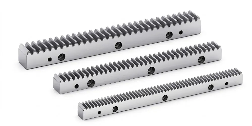
Helical Rack and Pinion Systems
Our helical rack and pinion systems are designed for direct pairing with the EP-Ground helical pinion gear series. Available in ground and hobbed variants, the helical rack converts rotary motion to linear displacement with the same smooth, low-noise engagement characteristics as the mating helical gear. Widely used in linear axis drives for CNC routers, plasma cutters, and automated sliding gate systems.
Жиі қойылатын сұрақтар
Редактор: PXY