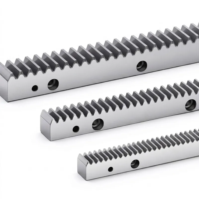
EP-S45C/42CrMo 4–8 Hole 20–212 Tooth Straight Gear Rack — DIN6 GB5 Spur Tooth Rack
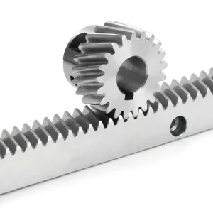
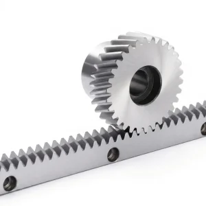
A gear rack is a linear bar with evenly spaced teeth cut along one face, designed to mesh with a rotating pinion gear. Together they form the rack and pinion gear mechanism — one of the most mechanically direct methods of converting rotary motion into controlled linear displacement. Unlike ball-screw or belt-driven linear axes, a spur gear rack drivetrain offers high stiffness, straightforward maintenance, and the ability to handle long travel distances by jointing multiple rack segments end to end.
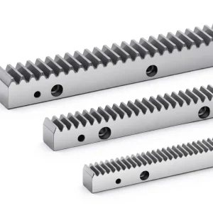
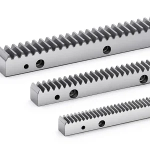
The EP-S45C/42CrMo range is manufactured in a broad matrix of module sizes to cover everything from compact small gear rack applications at M1.5 to heavy-drive axes at M12. Two material grades are offered within the same dimensional series: S45C carbon steel provides a cost-effective, machinable base suited to general-purpose CNC and automation drives, while 42CrMo alloy steel delivers a higher base strength and improved hardenability — favored in applications where shock loading, elevated temperatures, or high surface contact stress require additional material performance. Racks without mounting holes are available on request; simply add the suffix “N” to the model code (for example, 551020100-N) when placing an order.
All dimensions in the EP series follow the standard dimensional schema for gears rack and pinion systems: the pitch Pt equals the module multiplied by π, rack length L is determined by the tooth count and pitch, and all body and tooth dimensions — B, A0, A1, D, I, C1, C2, C3, E, D1, I1 — are listed in the full specification table below. Other dimensions or materials can be customized against customer drawings, giving engineers the flexibility to integrate this custom gear rack into non-standard machine configurations without redesigning the entire axis.
PRECISION STRAIGHT-TOOTH TRANSMISSION
EP-S45C/42CrMo 4–8 Hole 20–212 Tooth Straight Gear Rack — DIN6 GB5 Spur Tooth Rack
The EP-S45C/42CrMo gear rack series delivers reliable, high-precision linear motion across a comprehensive range of module sizes — from M1.5 to M12 — with tooth counts spanning 20 to 212. Built from high-quality S45C carbon steel or 42CrMo alloy steel, this straight gear rack is ground to DIN6 GB5 precision on all four body faces and the tooth surface, making it a dependable choice for CNC machine tools, automation systems, conveyor drives, and any application requiring an accurate, repeatable rack and pinion gear linear axis.
Technical Specifications
The tables below list the complete dimensional parameters for each gear rack model in the EP-551 straight-tooth series. All dimensions are in millimeters. The pitch Pt is calculated as module × π, and Fp is the total cumulative pitch error tolerance at DIN6 GB5 grade. When sourcing a linear gear rack replacement or specifying a new rack and pinion gear axis, cross-reference the module, tooth count, and body dimensions against your current or planned pinion center height to confirm correct installation geometry. Racks can be supplied without holes by appending "N" to the model number.
| Code | Module | Pt (mm) | L (mm) | Teeth | B | A0 | A1 | D | I | Holes | Fp |
|---|---|---|---|---|---|---|---|---|---|---|---|
| 551 010 050 | 1.5 | 4.7123 | 499.51 | 106 | 17 | 17 | 15.5 | 62.44 | 124.88 | 4 | 0.029 |
| 551 010 100 | 1.5 | 4.7123 | 999.03 | 212 | 17 | 17 | 15.5 | 62.44 | 124.88 | 8 | 0.033 |
| 551 020 050 | 2 | 6.2831 | 502.65 | 80 | 24 | 24 | 22 | 62.83 | 125.66 | 4 | 0.029 |
| 551 020 100 | 2 | 6.2831 | 1005.31 | 160 | 24 | 24 | 22 | 62.83 | 125.66 | 8 | 0.034 |
| 551 030 050 | 3 | 9.4247 | 508.94 | 54 | 29 | 29 | 26 | 63.62 | 127.23 | 4 | 0.032 |
| 551 030 100 | 3 | 9.4247 | 1017.88 | 108 | 29 | 29 | 26 | 63.62 | 127.23 | 8 | 0.037 |
| 551 040 050 | 4 | 12.5664 | 502.65 | 40 | 39 | 39 | 35 | 62.83 | 125.66 | 4 | 0.034 |
| 551 040 100 | 4 | 12.5664 | 1005.31 | 80 | 39 | 39 | 35 | 62.83 | 125.66 | 8 | 0.040 |
| 551 050 050 | 5 | 15.7079 | 502.65 | 32 | 49 | 39 | 34 | 62.83 | 125.66 | 4 | 0.034 |
| 551 060 100 | 6 | 18.8495 | 1017.88 | 54 | 59 | 49 | 43 | 63.62 | 127.23 | 8 | 0.040 |
| 551 080 100 | 8 | 25.1327 | 1005.31 | 40 | 79 | 79 | 71 | 62.83 | 125.66 | 8 | 0.043 |
| 551 100 100 | 10 | 31.4159 | 1005.31 | 32 | 99 | 99 | 89 | 62.83 | 125.66 | 8 | 0.043 |
| 551 120 100 | 12 | 37.6991 | 1017.88 | 27 | 120 | 120 | 108 | 63.6 | 127.23 | 8 | 0.046 |
All dimensions in mm. Pt = Module × π. Fp = Total cumulative pitch error (DIN6 GB5). Racks without holes available — suffix model with "N" (e.g. 551020100-N). Custom dimensions and materials available against drawing.
How the Straight Gear Rack Mechanism Works
The operating principle behind the spur gear rack and pinion system is direct and mechanically efficient. A circular pinion — typically driven by a servo motor or gearbox — rotates against the straight teeth of the gear rack. Because each tooth of the pinion meshes perpendicular to the rack's longitudinal axis, the rotational input translates cleanly into linear output. The distance the rack travels per full pinion revolution equals π multiplied by the module multiplied by the number of pinion teeth. This fixed gear ratio of rack and pinion relationship means positioning is entirely predictable and repeatable without encoder feedback on the rack itself.
Unlike ball-screw actuators, the rack and pinion gear drivetrain has no theoretical travel length limit — axes can be extended by bolting additional rack segments end to end in a pitch-matched arrangement. This is a significant advantage in large-format CNC routers, plasma cutting tables, and gantry cranes where a single screw would be impractical. The straight gear rack also accepts bidirectional loading without preload complications, making it well-suited for axes that must reverse direction frequently under load.
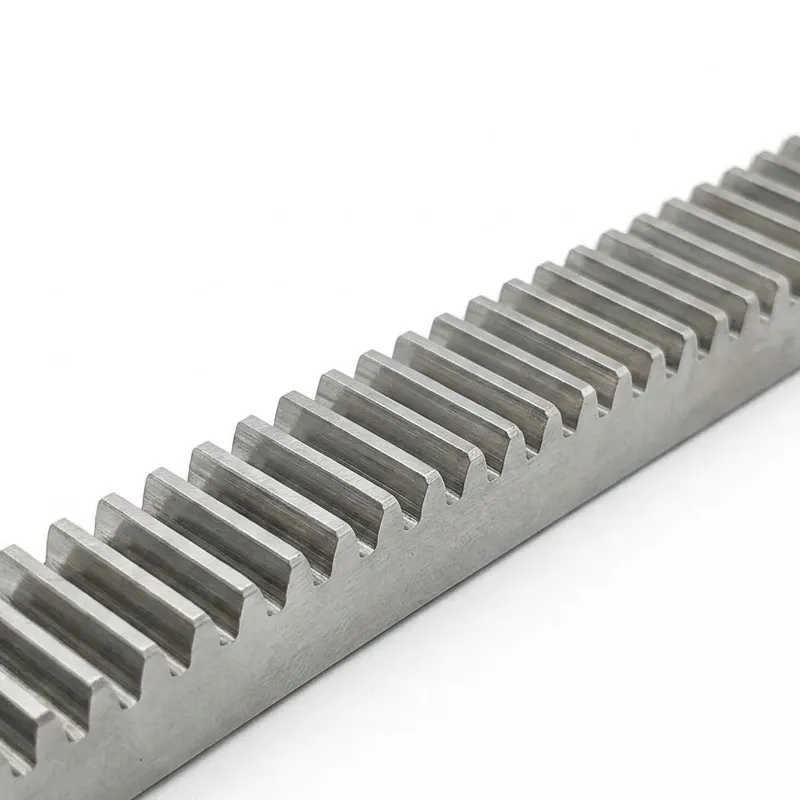
The EP-S45C/42CrMo series uses a standard full-depth straight tooth profile — teeth are machined perpendicular to the rack body, with tooth height proportional to the module. After the hard-tooth-surface treatment, all four body faces and the tooth flank are ground to DIN6 GB5 tolerance, correcting any post-hardening distortion and ensuring that the finished gear rack meets its pitch-accuracy specification across the full length.
5 Reasons Engineers Specify This Gear Rack
Offering both S45C carbon steel and 42CrMo alloy steel in the same dimensional series gives engineers a direct upgrade path when application loads increase. S45C is well-suited to general automation and positioning axes, while 42CrMo provides higher tensile strength and better fatigue resistance for axes carrying heavier payloads or operating under impact conditions — all without changing the pinion or mounting hardware.
Meeting both German DIN6 and Chinese GB5 precision grades, the EP series is qualified for direct use in European machine-tool specifications and Asian OEM procurement programs. The cumulative pitch error Fp — listed per model in the specification table — quantifies the allowable tooth-position tolerance across the full rack length, giving quality engineers a concrete acceptance criterion for incoming inspection of any linear gear rack shipment.
Tooth surfaces are induction-hardened to HRC 48–52° (S45C) or HRC 50–55° (42CrMo) in a focused zone at the contact face, preserving toughness in the body while delivering hard-wearing performance where it counts. This surface treatment is the same process used in heavy-duty gear rack applications for construction machinery and stage lifting systems, applied here to a precision-grade product that also serves lighter CNC and robotic axes.
The two-stage grinding process — first the four rectangular body faces, then the tooth profile — eliminates hardening-induced warp before the tooth geometry is finalized. Mounting faces that are ground square to the tooth pitch ensure the rack installs flat against its guideway or machine bed without shimming, reducing setup time on CNC routing tables, plasma gantries, and pick-and-place automation systems across manufacturing sites in Germany, the UK, Australia, and North America.
From M1.5 for compact small rack and pinion drives to M12 for large-format heavy-transport axes, the EP series covers practically every gearbox rack and pinion requirement in one catalogue. The optional hole-free variant (suffix "N") is useful when the machine frame is drilled to a different hole pattern, or when the rack is held by external clamps rather than through-bolts — a configuration common in retrofit and replacement scenarios.
Material, Hardness & Quality Standards
Two material grades serve this gear rack series, each targeting a distinct load and application profile. S45C medium-carbon steel is widely used in industrial machinery for its reliable machinability, consistent mechanical properties, and favorable response to high-frequency induction hardening — tooth surfaces reach HRC 48–52° while the body retains a working hardness that resists brittle fracture under dynamic loading. 42CrMo alloy steel adds chromium and molybdenum to the base composition, significantly improving hardenability, tensile strength, and fatigue resistance. Tooth surfaces on the 42CrMo variant are hardened to HRC 50–55°, making it the preferred choice for heavy-duty gear rack axes in construction equipment, stage platforms, and high-cycle industrial robots where both contact stress and body bending loads are elevated.
The manufacturing sequence begins with material verification and rough machining, followed by hard-tooth-surface treatment — high-frequency induction hardening concentrated at the tooth flank. The hardened blank then undergoes four-side body grinding, after which tooth surface grinding finalizes the profile to DIN6 GB5 tolerance. This sequencing is critical: grinding after hardening corrects any thermal distortion introduced during the heat treatment phase, ensuring the finished gear rack is straight and the tooth pitch meets the specification regardless of the material grade chosen.
Production is carried out under an ISO 9001:2015 certified quality management system. Each batch undergoes inspection of tooth pitch, profile form, and body squareness before dispatch. Custom dimensions and alternative materials can be supplied against customer drawings — a capability that extends the EP series beyond its standard catalogue into bespoke custom gear rack territory for OEM and retrofit projects worldwide.
Application Scenarios
The broad module range and dual-material offering of the EP-S45C/42CrMo gear rack makes it applicable across a wide spectrum of industries. Below are the environments where this spur gear rack is most commonly specified.
Large-format CNC routers used in furniture manufacturing, signage, and aerospace panel cutting rely on rack and pinion linear slide drives for gantry X-axis travel. The M3–M6 range from the EP series covers most router table widths, and the ground body faces simplify installation on aluminum extrusion or welded steel frames. Machine builders across the UK, Germany, and Australia regularly specify this class of straight gear rack for its combination of speed, stiffness, and serviceability.
Plasma and fiber laser cutting tables demand axes that maintain accurate positioning at high rapid-traverse speeds. The rack and pinion gear system is the industry standard for these applications because it allows unlimited axis length through rack jointing, accommodates the wide, low-profile machine frames typical of heavy sheet cutting, and tolerates the contamination environment — cutting dust, dross, and moisture — better than alternative lead-screw or belt drives with proper rack protection in place.
Stacker cranes and automated storage and retrieval systems in warehouse logistics use linear rack and pinion drives on both the horizontal travel axis and the lifting column. The heavy-duty gear rack in M8–M12 sizes handles the payload capacity required for pallet-height racking systems, while the consistent pitch accuracy of the DIN6-graded rack supports the position feedback accuracy that inventory management systems rely on.
In rack and pinion press configurations and punch press tooling, the rack converts motor torque into controlled ram force. The 42CrMo variant is particularly suited here, given the shock and impact loads that occur at the end of the press stroke. The high surface hardness also resists the fretting wear that develops on press rack teeth where the engagement zone is concentrated over a short travel.
Concert stage lifts, theatrical flying systems, and broadcast camera dollies use gear rack drives for smooth, quiet, and precisely controllable linear motion. The gears rack and pinion combination in these systems must operate reliably through heavy touring cycles and rapid rigging changes. The EP series 42CrMo variant, with its higher fatigue strength, suits the structural demands of vertical lift and lateral travel axes where safety factors are regulated.
The drill press gear rack is one of the oldest applications of the rack and pinion principle. The EP M2–M4 models replace worn racks in radial drills, pillar drills, and milling-head quill feeds. Because the EP range is produced to DIN6 tolerance, replacement units fit the same pinion without adjustment — a practical consideration for maintenance teams replacing worn components in production environments in North America, Korea, and Brazil.
Compatible Components & Related Products
A gear rack performs best when paired with the right mating pinion and complementary drive components. We supply a range of products engineered to work alongside the EP straight rack series, allowing procurement teams to source a complete rack and pinion gear drivetrain from one supplier — eliminating tooth-geometry compatibility risk and reducing lead time on complete axis assemblies.
While the EP straight rack meshes with spur pinions, many engineers opt for a Helical Gear pinion on axes where noise reduction is a priority. Our full helical gear range covers a broad span of module sizes and bore diameters compatible with the EP rack series, giving designers the flexibility to select between straight-tooth and helical-pinion engagement geometry within a single product ecosystem. This one-supplier approach to the complete rack pinion gear system simplifies specification and ensures consistent tooth-form matching between rack and pinion.

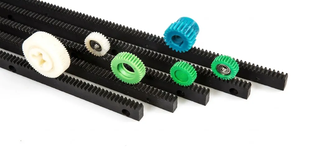
For applications where weight, corrosion resistance, or self-lubricating properties take precedence over maximum load capacity, our plastic gear rack range is dimensionally compatible with the metal EP series at equivalent module sizes. This allows machine designers to specify metal racks on primary load-bearing axes and polymer racks on lighter auxiliary axes — both sourced from the same supplier catalog with no module mismatch. The plastic rack and pinion option is widely used in food processing, laboratory automation, and office equipment across European and North American markets.
About Our Manufacturing Operation
With over ten years of focused experience in mechanical power transmission, our production facility designs and builds precision gear components and drive assemblies for industrial customers worldwide. Our product range extends across agricultural gearboxes, worm gear reducers, planetary gear drives, power take-off shafts, hydraulic cylinders, chains, and motors — all manufactured under one roof and covered by ISO 9001:2015 certification.
We engineer and produce a broad catalogue of gearbox assemblies in ductile iron, cast iron, cast steel, precision cast steel, and cast aluminum, alongside standard mechanical parts including gears, sprockets, worm gears, pulleys, worms, and shafts. Non-standard components can be manufactured to customer drawings — a capability that makes us a practical partner for OEM machine builders who need a reliable source for both catalogue items like this custom gear rack and bespoke parts within the same order.
WorkShop




Frequently Asked Questions
Editor: PXY