
Textile & Garment Manufacturing
A technical reference for textile engineers and machine builders covering worm gear speed reducer selection, construction, and integration in ring spinning and open-end spinning drive systems that require stable twist-per-inch control across global production environments.
In ring spinning and open-end spinning, twist per inch (TPI) is among the most critical yarn quality parameters. It determines yarn strength, elongation, evenness, and the handle of the finished fabric. A yarn spun at 18 TPI for a fine worsted application must maintain that twist value within tight tolerance over the entire production run — even across dozens of spindle positions on a single frame — because any twist variation shows in the finished fabric as uneven lustre, differential dye uptake, or reduced tear strength. These are not cosmetic defects; they trigger rejection at the weaving or knitting stage and represent significant production loss.
The twist inserted into the yarn is directly controlled by the ratio of spindle speed to delivery speed — the rate at which the drafted fibre ribbon exits the front roller of the drafting zone. If the spindle speed is fixed, any variation in the front-roller speed changes the TPI. The mechanical device that sets and stabilises the front-roller drive speed — the single speed reducer — therefore occupies a direct causal position in the twist control chain. A single speed reducer with poor speed stability, excessive backlash, or thermally drifting efficiency transfers its mechanical inconsistency directly into twist variation.
This article covers the engineering fundamentals of single speed reducer selection and application in ring spinning and spinning machine drives, with attention to construction, material systems, gear reduction ratio calculation, and operational considerations relevant to textile plants across major producing regions — from the cotton spinning mills of India, Pakistan, and Bangladesh to the woollen and synthetic fibre facilities of Italy, Turkey, and Vietnam.

Twist Per Inch and the Mechanical Drive Chain
The twist per inch in a ring-spun yarn is governed by a straightforward mechanical relationship: TPI equals spindle revolutions per minute divided by the surface speed of the front roller (in inches per minute). Because the spindle speed on a conventional ring frame is fixed by a flat belt drive to the main line shaft, the variable that controls TPI is the front-roller surface speed, which is in turn set by the gear train connecting the main line shaft to the front roller. The single speed reducer sits at a key point in this gear train, providing the bulk of the speed reduction from the motor or line-shaft speed down to the front-roller speed that produces the target TPI for the yarn count being spun.
The relationship is not just about setting the correct average ratio. It is about maintaining that ratio consistently over time, through changes in ambient temperature, changes in load as the cop builds on the spindle, and through the minor speed oscillations that all electrical drives introduce. Any torsional compliance in the gear train — arising from backlash at a gear mesh, from shaft bending between widely spaced bearings, or from oil film thickness variation in a poorly lubricated worm mesh — appears as a cyclic variation in the front-roller speed and therefore as a periodic TPI fluctuation along the yarn. When this fluctuation occurs at a wavelength that corresponds to the repeat length of the fabric structure, it produces a visible striping defect.
The worm gear speed reducer minimises this risk through two mechanisms: its single-mesh kinematic chain limits the number of sources of torsional error, and the sliding contact between the worm thread and the bronze wheel tooth provides inherent damping that absorbs minor drive-side oscillations before they reach the front roller. These properties make the single reduction worm reducer the dominant choice for drafting zone drives on ring spinning frames across global textile machinery production.
Manufacturing Construction
The housing of a single speed reducer for textile machine service is pressure-cast or gravity-cast in close-grained grey cast iron, then machined on all bore centres and mounting faces to close geometric tolerances. Bore centre accuracy — the parallelism and centre distance between the worm shaft bore and the worm wheel output shaft bore — is the most important dimensional parameter, because any deviation shifts the worm gear mesh out of its designed tooth contact pattern, changing the effective transmission ratio and introducing a cyclic output speed variation that repeats at the worm wheel frequency. For a 20:1 reducer driving a ring-frame front roller, this would produce a twist variation pattern repeating every 20 revolutions of the worm — a wavelength that can cause visible periodicity in certain yarn counts.
The worm shaft is supported on preloaded angular-contact bearings or tapered roller bearings at both shaft ends. Bearing preload eliminates axial float in the worm shaft, which would otherwise allow the worm thread to shift axially within the worm wheel during load reversals — a condition that generates a momentary output speed discontinuity. On a ring frame where the front-roller load is relatively light and steady, standard preloaded deep-groove ball bearings are adequate for the worm shaft, but the preload must be set correctly during assembly and verified during the first commissioning check.
The output shaft on textile-service reducers is typically a solid cylindrical shaft with a standard keyway, connecting to the roller drive train via a chain sprocket or a flexible coupling. The output shaft is carried on deep-groove ball bearings sized to handle the combined radial load from the driven sprocket and the tangential load from the worm wheel. For spinning machine applications where lint and fibre can accumulate around shaft penetrations, the lip seals must be specified with a dust-exclusion capability — either a double-lip seal with a grease-filled cavity or a labyrinth arrangement — to prevent fibre ingress that would contaminate the oil and accelerate abrasive wear.
The housing design typically incorporates a flat, machined base for foot-mounting and tapped holes on the face for optional flange-mount adapters. The access plug for oil level checking should be positioned to be accessible without removing the reducer from the machine frame — a practical requirement on ring frames where drive-side space is limited by the creel and the bobbin rail assembly.
Material Systems
The worm shaft in standard WP-series single speed reducers is machined from 45# high-carbon steel, surface-hardened by induction heating to 45–55 HRC, and finish-ground on the thread flanks to a surface roughness in the range of Ra 0.4–0.8 µm. The grinding step is particularly important in textile drive applications because the roughness of the worm flank determines how quickly the elastohydrodynamic oil film establishes itself at low load and low sliding speed — conditions that occur during machine startup and during slow inching operations for threading or doffing. A finely ground worm flank generates a stable oil film faster and at lower speed, reducing the brief period of boundary lubrication that occurs at each startup and accumulates as wear over a machine’s service life.
The worm wheel is centrifugally cast from tin bronze — typically CuSn10Pb1 or a comparable phosphor bronze alloy — and then hobbed to the final tooth profile. Tin bronze provides the combination of moderate hardness, excellent conformability under contact stress, and a low coefficient of friction against hardened steel that the worm gear mesh requires. In a textile plant environment, the worm wheel is also exposed to cyclically varying loads as the bobbin builds on the spindle and the cop weight increases; the ability of tin bronze to work-harden slightly at the tooth contact surface during this period distributes the increasing load over a progressively larger contact area, stabilising the mesh over the full doffing cycle.
The housing in standard units is cast from HT200-grade grey cast iron, offering adequate compressive and bending strength for all normal spinning machine loads. For environments where the housing external surface is exposed to alkaline or acidic processing chemicals — a genuine concern in integrated spinning-and-dyeing facilities — an epoxy or polyurethane top coat extends the housing’s corrosion resistance to acceptable service intervals. Internal surfaces in the oil sump are not coated; the oil itself provides the corrosion barrier, provided the correct lubricant is used and the change intervals are respected.

Gear Reduction Ratio Selection for Spinning Machine Drives
The starting point for ratio selection in a ring spinning application is the TPI specification for the yarn count being produced. Once the target TPI and the front-roller diameter are known, the required front-roller shaft speed in rpm can be calculated. The single speed reducer then provides the ratio that steps the motor or line-shaft speed down to that front-roller speed. Standard worm gear reduction ratios of 10:1, 15:1, 20:1, 25:1, 30:1, 40:1, and 60:1 cover the full range of front-roller speeds encountered across yarn counts from coarse Ne 6 cotton through fine Ne 80 combed cotton or wool.
For coarse count yarns requiring low TPI — for example, Ne 10 cotton at 10–12 TPI — the front roller runs relatively fast and the required reducer ratio is low, typically 10:1 or 15:1. For fine count yarns requiring high TPI — Ne 60 cotton or 2/60 worsted at 25–35 TPI — the front roller must run much more slowly for the same spindle speed, requiring a 30:1 or 40:1 single reduction. This ratio range maps exactly onto the standard catalogue of single stage right-angle worm-gear speed reducers, making it straightforward to select the appropriate ratio by calculation rather than by trial.
In multi-count spinning facilities — particularly in India, Turkey, and Pakistan where the same spinning room may produce multiple yarn counts on the same frame model — the practical approach is to select a reducer housing that accommodates interchangeable worm gear sets at different ratios. When the product mix changes, the ratio is altered by replacing the worm and wheel set inside the same housing, without disturbing the mounting arrangement. This approach reduces the number of spare housing variants to stock while preserving flexibility in the production programme.
Technical Parameters: EP-WPKS 4–365 kg Single Speed Reducer
The EP-WPKS 4–365 kg Single Speed Reducer is a foot-mounted, right-angle worm gear speed reducer with a load capacity range suited to drafting-zone and roller-drive applications on ring spinning and open-end spinning frames of various sizes.
| Parameter | Specification | Relevance to Spinning Machine Drive |
|---|---|---|
| Gearing Type | Single-stage worm gear | Single mesh — minimal source of output speed error |
| Load Capacity | 4 – 365 kg | Covers full range from small lab frames to industrial long frames |
| Standard Reduction Ratios | 10:1 to 60:1 | Covers coarse Ne 6 through fine Ne 80 yarn counts |
| Worm Material | 45# steel, induction-hardened, ground | Ground flanks stabilise oil film formation at low startup speed |
| Worm Wheel Material | Tin bronze (CuSn10Pb1) | Stable friction coefficient; self-conforming under variable cop load |
| Housing Material | Grey cast iron HT200 | Vibration damping; rigid under overhung sprocket loads |
| Shaft Orientation | Right-angle | Fits compact drive-side envelope of ring frame headstock |
| Sealing | Lip seals at all shaft penetrations | Prevents fibre and lint ingress into oil sump |
| Oil Capacity | 0.4 – 5.2 L (frame-dependent) | Adequate thermal buffer for long continuous-run shift patterns |
| Mounting | Foot-mount; flange adapter optional | Bolt-on fitment to standard ring-frame headstock plates |
Indicative TPI and Reducer Ratio by Yarn Count
The table below provides indicative relationships between yarn count, target TPI, and the corresponding single speed reducer ratio for a ring frame running at 12,000 rpm spindle speed. Actual values depend on the specific machine model and the draft system geometry.
| Yarn Count (Ne) | Typical TPI Range | Approximate Reducer Ratio | Fibre Type |
|---|---|---|---|
| Ne 6 – Ne 12 | 8 – 14 TPI | 10:1 – 15:1 | Coarse cotton, jute blends |
| Ne 16 – Ne 30 | 14 – 20 TPI | 15:1 – 25:1 | Medium cotton, polyester blends |
| Ne 32 – Ne 50 | 20 – 28 TPI | 25:1 – 35:1 | Combed cotton, viscose |
| Ne 60 – Ne 80 | 28 – 38 TPI | 40:1 – 60:1 | Fine combed cotton, worsted wool |
Recommended Product for Spinning Machine Drive Applications
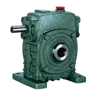
EP-WPKS 4–365 kg Single Speed Reducer
A foot-mounted, right-angle single stage worm gear speed reducer with a load capacity range of 4–365 kg and standard ratios from 10:1 to 60:1. The ground worm shaft and tin-bronze wheel deliver the stable output speed that TPI-critical spinning machine drives demand, while the cast iron housing and dual-lip shaft seals provide the durability and contamination protection required in a lint-laden textile plant environment. Interchangeable worm gear sets allow ratio changes without replacing the housing — an advantage in multi-count spinning facilities.

Operational Considerations in Textile Production Environments
Textile mills — particularly cotton spinning plants — present a challenging environment for mechanical drives. Airborne fibre and lint settle on every external surface, including the reducer housing, oil seals, and vent plugs. Accumulated lint on the housing acts as an insulating layer that traps heat, raising the operating temperature of the oil and accelerating its oxidative degradation. Regular housekeeping — clearing lint from the reducer housing during the cleaning cycle — is as important as the oil change schedule for maintaining reducer service life in a spinning room.
The vent plug on the reducer housing must be a filtered type that allows pressure equalisation as the oil temperature cycles during the production shift without admitting lint or dust. Standard solid plugs used in other industrial environments are not suitable for a spinning room installation; a vent plug with a sintered bronze or fibrous filter element is the appropriate specification. Some operators replace the standard vent with a sealed, pressurised oil fill arrangement to eliminate the vent path entirely, relying on the calculated thermal expansion of the oil volume to remain within the housing capacity — an approach that requires careful oil fill level management.
Lubrication of single speed reducers in spinning rooms typically uses ISO VG 220 mineral oil for ambient temperatures up to 30°C, stepping up to ISO VG 320 in hotter environments — common in South Asian spinning plants operating through summer months where machine room temperatures can exceed 35°C. The initial oil change after 100 operating hours remains important even in light-duty textile applications, because the run-in of the bronze worm wheel generates copper-bearing wear debris that should be removed before it recirculates through the mesh and acts as an abrasive. Subsequent change intervals in a clean, temperature-controlled spinning room are typically 3,000–4,000 hours for mineral oil.
Related Products: Integrated Drive System Supply
The single speed reducer performs as designed only when the upstream motor and the downstream mechanical components are correctly matched. Two product families from the same manufacturing base integrate directly with this reducer range.

Electric Motors
IEC-frame electric motors with shaft dimensions matched to the WP-series reducer input bore configurations. Available across the motor sizes relevant to ring spinning and open-end spinning drives, from small drafting-zone motors through the larger motors used on frame main drives, ensuring dimensional compatibility and simplifying single-source procurement.

Full-Series Worm Gearbox
The complete worm gearbox range spans housing sizes from 40 mm through 250 mm centre distance. For textile machinery builders who need a single-source mechanical drive solution across multiple machine types — from winding and twisting frames to warping machines — this range provides ratio and dimensional continuity that simplifies engineering and after-sales spare parts management.
About the Manufacturer
The product range is manufactured under ISO 9001:2015 certification at a facility with in-house capability across worm gear reducers, planetary gear drives, agricultural gearboxes, power take-off shafts, hydraulic cylinders, gears, chains, and motors. Both standard catalogue products and custom OEM assemblies are engineered and produced internally, using materials including ductile iron, cast iron, cast steel, precision cast steel, and cast aluminium. Worm gears, sprockets, pulleys, worm shafts, and precision machined components are all manufactured on-site, allowing engineering control over dimensional quality from raw casting through to final inspection.
WorkShop




Frequently Asked Questions
Which single speed reducer ratio should I select for spinning Ne 40 combed cotton yarn at 22 TPI on a ring spinning frame running 12,000 rpm spindle speed in an Indian or Pakistani textile mill?
For Ne 40 combed cotton at 22 TPI with a standard 25 mm front-roller diameter and 12,000 rpm spindle speed, the required front-roller speed is approximately 55 rpm. On a 1450 rpm motor, this requires a reduction ratio of approximately 26:1. The nearest standard ratio is 25:1, which gives 58 rpm — the remaining 5% difference is corrected by adjusting the motor pulley diameter or, on variable-speed equipped machines, by a VFD frequency trim. A 25:1 single stage right-angle worm-gear speed reducer is the standard selection for this specification range across ring-spinning plants in South Asia.
What type of oil and change interval is recommended for a single speed worm gear reducer on a cotton ring frame running three-shift operations in a high-humidity textile facility in Bangladesh or Vietnam?
For three-shift continuous operation in a high-humidity tropical environment, ISO VG 320 mineral oil or synthetic PG 320 is the recommended lubricant for worm gear speed reducers in cotton spinning service. The higher viscosity grade maintains adequate film thickness in the worm mesh when the housing temperature rises during the third shift. The first oil change must be performed after 100 operating hours to remove bronze run-in particles; thereafter, mineral oil should be changed every 2,500–3,000 operating hours in a clean spinning environment, or every 4,000–5,000 hours with synthetic PG oil. In facilities where lint accumulation on the housing is heavy, more frequent oil analysis is advisable.
How does a single reduction worm reducer prevent twist variation from occurring at the front roller of a ring spinning frame in a worsted wool spinning plant in Italy or Turkey?
The single reduction worm reducer maintains consistent front-roller speed through two mechanisms. The single gear mesh limits the kinematic chain to one contact point where speed error can be introduced — unlike multi-stage gearboxes where positional error accumulates across each stage. The sliding contact between the hardened worm thread and the bronze wheel tooth also provides inherent mechanical damping that absorbs minor torsional pulses from the electrical drive before they reach the front roller. Both effects directly reduce the cyclic front-roller speed variation that would otherwise appear as periodic twist fluctuations along the yarn, causing barre defects in the finished fabric.
Where can a textile machinery manufacturer or spinning mill in Europe or Southeast Asia get a quote for a customized single speed reducer with a non-standard ratio for a specific yarn count programme?
Customized single speed reducers with non-standard ratios — for example, a 28:1 or 35:1 ratio for a specific worsted count programme — are available from manufacturers offering OEM engineering services. An enquiry should specify the required output shaft speed, peak torque, service factor, shaft configuration, and any special sealing requirements for the textile environment. Suppliers with in-house worm gear cutting capability can produce non-standard ratios within the same housing frame at modest cost premium on volumes of ten or more units. Lead times for modified units typically fall between four and eight weeks from order confirmation.
What are the signs that a worm gear speed reducer on a ring spinning frame is causing twist variation and needs servicing or replacement before yarn quality is affected?
The earliest detectable sign is an increase in yarn TPI coefficient of variation (CV%) measured on an evenness tester, particularly when the variation shows a periodic pattern at a wavelength corresponding to the output shaft revolution length. Mechanically, a worn reducer will show increased output shaft angular play when the shaft is manually rocked with the motor stopped — this is measurable backlash growth from worm wheel tooth wear. Elevated housing temperature above the established baseline, increased noise from the mesh, and copper-coloured oil on the drain plug thread are additional indicators. When any of these appear systematically, a planned replacement during the next machine maintenance cycle prevents further degradation of yarn quality output.
Editor: PXY