
Automotive & Heavy Equipment — Application Focus
A practical engineering reference covering single speed reducer selection, drive system architecture, and maintenance strategy for conveyor and lift table drives in automotive manufacturing plants worldwide.
The Role of the Single Speed Reducer in Automotive Production Environments
Automotive assembly plants are among the most demanding environments for drive system components. The conveyor lines that move body shells, chassis frames, powertrain subassemblies, and trimmed vehicle bodies through assembly stations operate continuously across three-shift production cycles — often 20 or more hours per day during peak production periods at plants in Germany, Japan, the United States, South Korea, and Mexico. Lift tables elevate and precisely position heavy vehicle subassemblies for ergonomic operator access at specific work heights. Both of these drive types share a common requirement: reliable, controlled speed reduction from a standard motor output to the lower shaft speed that the application actually demands.
The single speed reducer fills this role across both conveyor and lift table applications. In conveyor drives, a single stage speed reducer converts the motor’s rated speed — typically 960 to 1,450 RPM — to the lower chain or belt drive shaft speed that moves the assembly line at the programmed throughput rate. In lift table drives, the single speed worm gear reducer provides not only speed reduction but also the inherent self-locking that prevents a loaded table from lowering under gravity when the motor is de-energised — eliminating the need for a separate brake in many configurations.

Manufacturing Structure & Material System
Housing Construction for High-Cycle Duty
Automotive conveyor and lift table applications place a single speed reducer in high-cycle service — potentially millions of starts and stops over the system’s design life. The housing must absorb the dynamic shock loads transmitted at each conveyor indexing step or lift table reversal without developing fatigue cracks at bearing boss transitions. HT250 grey cast iron is the standard material for automotive-grade worm gear reducer housings, providing adequate tensile strength and natural vibration damping. All bearing bores are finish-machined in a single fixture to ensure axial alignment; housing mating faces are ground flat to prevent gasket extrusion that could cause oil leakage onto the production floor — a condition that triggers immediate shutdown in automotive body shop environments.
Worm Shaft: Alloy Steel with CNC Ground Profile
The worm shaft in an automotive single speed gear reducer operates under high-cycle reversing torque loads in lift table drives and sustained unidirectional load in conveyor drives. Material selection is 20CrMnTi alloy steel, carburised and case-hardened to HRC 56–62, with the worm thread profile CNC-ground post hardening to achieve consistent lead accuracy. The grinding step is what separates a production-quality single reduction worm reducer from a commodity unit: a hobbed-only worm shaft has significant surface roughness on the thread flanks that generates elevated contact stress and heat during the initial operating hours, accelerating worm wheel wear in the high-cycle automotive environment.
Worm Wheel: Bronze Rim on Ductile Iron Body
The worm wheel in any worm speed reducer is the primary wear element. For automotive assembly line service where replacement access is difficult — conveyors are often integrated into the plant structure and cannot be easily removed for gearbox swap-out — the worm wheel must achieve the longest possible service life. ZCuSn10P1 tin-phosphor bronze centrifugally cast and precision hobbed to final tooth form is the standard specification. The bronze rim is mechanically fixed and dowelled to a ductile iron wheel body, preventing rim rotation under the reversing shock loads of a lift table drive. Bronze rim thickness is dimensioned to allow at least one re-profile of the tooth form if surface pitting occurs, extending effective service life without housing replacement.
Bearing Arrangement for Mixed Loading
Automotive conveyor drives impose predominantly radial loads on the output shaft of the single speed reducer — from chain or belt tension — while lift table drives impose combined radial and axial thrust that varies with the lift mechanism geometry. The output shaft bearing arrangement must accommodate both cases. Paired tapered roller bearings, pre-set to a controlled axial clearance, are used on the output shaft in the WPKS and WPDKA series units typically specified for lift table drives. Input shaft bearings in the WPDS flange-input series are deep-groove ball bearings sized for the radial load from the motor shaft extension, with the flange face providing positive axial location of the motor without lateral shaft loads on the gearbox input bore.
Conveyor Drive Architecture in Automotive Assembly Plants
Automotive assembly line conveyors use several distinct mechanical architectures — overhead monorail conveyors, floor-level slat conveyors, skillet conveyors, and accumulation roller conveyors among them — and the single speed reducer specification differs meaningfully between them. Overhead power-and-free conveyors typically drive a continuous chain at 4–12 metres per minute using a single speed gear reducer with a ratio of 1/20 to 1/40, delivering the precise low-speed torque that maintains consistent spacing between carriers. Floor-level skillet conveyors at trim and final assembly plants in Germany and the USA operate at slightly higher speeds — 8–20 metres per minute — and may use a WPX or WPDS series single speed reducer in a close-coupled motor-gearbox arrangement to maintain the compact drive footprint that fits within the pit or trench below the conveyor deck.
A critical design consideration for conveyor drive single speed reducers in automotive plants is synchronisation — in long conveyor loops driven by multiple motors and gearboxes, all units must maintain the same output shaft speed within a tight tolerance. This is typically managed through variable-frequency drives on the input motors, with the single stage speed reducer providing the fixed ratio that translates the VFD-controlled motor speed to the chain drive speed. The worm gear reduction ratio selection must account for the full VFD speed range, ensuring that the reducer operates within its thermal rating across the entire speed envelope, including during slow-speed creep modes used for maintenance access.

Lift Table Drive Systems: Self-Locking and Load-Holding Requirements
Ergonomic lift tables at automotive assembly stations serve a specific purpose: they position heavy vehicle subassemblies — instrument panels, door trim, seat frames, engine subframes — at the operator’s working height, reducing musculoskeletal injury risk. In German and Japanese automotive plants operating under stringent ergonomic standards, lift table positioning accuracy is specified to within 10–20 mm and holding stability under asymmetric loading is a defined performance criterion. The single speed reducer selected for a lift table drive must meet both of these requirements without a supplementary brake in most standard installations.
The worm gear’s self-locking property at higher reduction ratios is the mechanical feature that makes a single speed worm reducer the preferred choice for lift table drives over helical or planetary units of equivalent power. At ratios of 1/30 and above — typical for scissor-lift and parallelogram-link table designs used in automotive trim shops — the lead angle of the worm thread falls below the friction angle of the bronze-on-steel contact, preventing the load from backdriving the worm. This means the table holds its height when the motor is de-energised without any electrical brake or mechanical locking device. For plants operating under IEC 61508 functional safety frameworks, this mechanical self-lock serves as a passive safety measure that does not depend on electrical power availability.
Drive Type Comparison: Conveyor vs Lift Table Single Speed Reducer Selection
Key parameter differences between conveyor and lift table single speed reducer applications in automotive assembly plants. Both columns assume a standard four-pole motor input at 50 or 60 Hz.
| Parameter | Conveyor Drive | Lift Table Drive |
|---|---|---|
| Typical output speed (RPM) | 30 – 120 | 15 – 50 |
| Common reduction ratio | 1/10 – 1/25 | 1/25 – 1/60 |
| Load type | Continuous, radial | Cyclic, axial + radial |
| Self-locking required | Not typical | Yes — at ratio 1/30+ |
| Recommended series | WPDS / WPZ | WPKS / WPDKA |
| Seal specification | NBR lip seal | NBR + labyrinth option |
| Lubricant grade | ISO VG 220 mineral | ISO VG 220 mineral or PAO |
| Service factor (S.F.) | 1.25 – 1.5 | 1.5 – 2.0 |
| Typical input power range | 0.37 – 5.5 kW | 0.75 – 7.5 kW |
Recommended Single Speed Reducer Units for Automotive Assembly Drive Applications
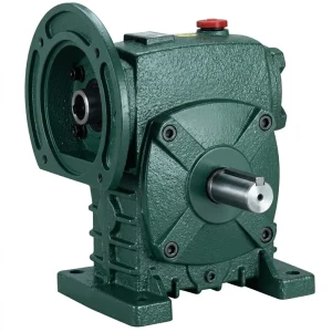
EP-WPDS Single Speed Reducer (0.12–15 kW)
The WPDS flange-input single speed reducer covers 0.12 to 15 kW input power with direct IEC motor face connection. Its compact motor-integral profile suits automotive conveyor drive arrangements where the drive unit must fit within a confined pit or trench below the conveyor deck. Available with ratios from 1/5 to 1/60, the WPDS is the standard specification for overhead monorail and floor-level slat conveyor drives in automotive plants across Germany, Japan, and the USA. The direct flange connection removes coupling alignment variables and reduces the total drive axial length — both practical benefits in new plant installations where drive pit dimensions are fixed early in the civil design process.
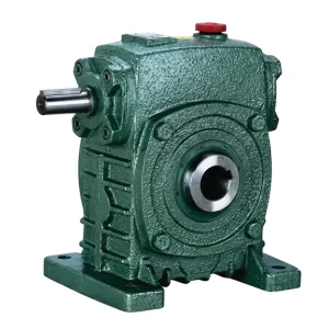
EP-WPKS Single Speed Reducer (4–365 kg)
The WPKS series single speed reducer is designed for heavy output shaft loading — making it the preferred selection for lift table lead screw and rack-and-pinion drives in automotive trim and final assembly stations. The reinforced output shaft bearing arrangement handles the combined radial and axial thrust generated by scissor-lift mechanisms under asymmetric vehicle subassembly loading. Unit weights from 4 to 365 kg indicate the range available — from small ergonomic workstation lifts up to heavy body-framing station tables that position underbody assemblies weighing several hundred kilograms. At ratios of 1/40 and above, the WPKS provides reliable mechanical self-lock without supplementary braking.
Lubrication and Planned Maintenance in Automotive Plant Environments
Automotive assembly plants in Mexico, South Korea, and the United States typically operate total productive maintenance (TPM) programmes where planned downtime for gearbox servicing is scheduled during weekend shutdowns or model changeover periods. The single speed reducer maintenance plan must align with these scheduled windows, meaning the lubricant drain interval is a specification input rather than an afterthought. ISO VG 220 mineral worm gear oil is the standard fill for most automotive-grade worm reducer gearbox installations, providing adequate film thickness at operating temperatures of 50–75°C in well-ventilated assembly plant environments.
For lift table drives that cycle continuously — in high-throughput plants where a lift table operates 200 or more cycles per shift — the oil temperature may stabilise higher than for a steady-state conveyor drive, because each reversal generates a brief torque spike that dissipates as heat. In these applications, a synthetic polyalphaolefin (PAO) ISO VG 220 lubricant is often preferred over mineral oil, as it maintains lower oil film temperature and extends the drain interval. The first oil change on any new single speed reducer should occur at 500 operating hours to remove running-in wear particles; subsequent intervals of 3,000 hours or 24 months (whichever comes first) are typical for automotive plant service when using quality mineral gear oil.

Noise and Vibration Control in Assembly Plant Drive Systems
Automotive assembly plants — particularly trim and final assembly zones where operators work in close proximity to moving equipment for sustained periods — are subject to workplace noise regulations in all major manufacturing countries. In European Union plants operating under the Physical Agents (Noise) Directive 2003/10/EC, the action level of 80 dB(A) applies to operator time-weighted exposure. The drive systems in conveyor and lift table equipment contribute to the ambient noise level in these areas, and the single speed reducer selection can meaningfully affect whether a specific conveyor installation meets the 80 dB(A) action level without supplementary noise attenuation measures.
The worm gear mesh in a worm speed reducer is inherently quieter than a helical or spur gear mesh at equivalent power and speed, because the sliding contact between worm thread and wheel tooth generates less impact noise than the involute tooth engagement of parallel-axis gears. This characteristic makes the worm gear reducer gearbox a preferred choice in assembly areas where tooling noise budgets are already at the regulatory limit. The noise advantage is most pronounced at low-to-medium output speeds — exactly the range typical of automotive conveyor drives. The principal noise sources in a worm gear reducer installation are bearing noise (managed by correct preload and lubrication) and chain or belt drive noise downstream of the gearbox, which is the dominant source in most conveyor configurations.
Compatible Drive System Components
The single speed reducer is one element of a complete conveyor or lift table drive package. Matched electric motors and a full worm gearbox range are available from the same source — simplifying procurement, ensuring documented dimensional compatibility, and providing a single point of technical contact for drive system specification support.
Electric Motors
IEC B3 and B5 flange motors from IE2 and IE3 efficiency classes, matched to the input flange dimensions of the WPDS, WPKS, and WPDKA single speed reducer series. Supplying motor and gearbox as a verified matched pair eliminates the shaft diameter and bolt-circle mismatch risk that arises when components are sourced from separate suppliers — a particular concern for automotive plant procurement where commissioning access windows are short. Explore motor options at Electric Motors.

Worm Gearbox Range
The full worm gearbox range covers NMRV compact units through heavy industrial WP-series configurations — providing complementary options for secondary drive positions in automotive plant equipment such as assembly fixture indexing drives, parts bin rotation systems, and line-side ergonomic positioning aids. For plants that prefer sourcing all gearbox types from a single catalogue, this breadth eliminates vendor qualification duplication. Browse the full worm gearbox range at Worm Gearbox.

Manufacturing Background
Our production range covers industrial gearboxes, worm gear reducers, planetary drive units, power take-off shafts, hydraulic cylinders, gears, roller chains, and motors — built to support complete drive package sourcing from a single supplier. The facility holds ISO 9001:2015 certification, with gear cutting, heat treatment, tooth grinding, and assembly all performed in-house under a documented quality management system.
We design and produce standard and custom industrial and agricultural gearboxes and assemblies in ductile iron, grey cast iron, cast steel, precision investment cast steel, and cast aluminium. The component catalogue extends to gears, sprockets, worm gears, pulleys, worms, shafts, and non-standard mechanical transmission parts manufactured to buyer drawings. For automotive and heavy equipment sector buyers, full documentation packages — including ISO 9001 certificates, material test records, gear inspection reports, and factory run-test data — are available on request.
WorkShop




Frequently Asked Questions
Q1. What single speed reducer ratio should I specify for an overhead power-and-free conveyor in an automotive body shop in Germany running at 8 metres per minute with a 1,450 RPM motor?
Start by calculating the required drive sprocket speed from the conveyor velocity and sprocket pitch circle diameter. For a typical 100 mm pitch circle sprocket driving a 38.1 mm pitch chain at 8 metres per minute, the sprocket turns at approximately 25 RPM. Dividing the motor speed (1,450 RPM) by the required sprocket speed (25 RPM) gives a required ratio of approximately 1/58 — within the 1/60 maximum available from the WP-series worm gear speed reducers in catalogue range. Apply a service factor of 1.25 to 1.5 for the conveyor duty cycle before selecting the housing size. A 1/60 ratio worm gear reducer in the WPDS or WPZ series would suit this application, subject to power and torque verification at the selected housing size.
Q2. How do I verify that a single speed worm gear reducer provides enough self-locking force to hold a loaded lift table in a South Korean automotive trim assembly station without a secondary brake?
Self-locking in a worm gear reducer is reliable when the lead angle of the worm is less than the friction angle of the worm mesh. For ZCuSn10P1 bronze against hardened steel with a well-lubricated contact, the friction angle is typically 6–9 degrees. Worm lead angle at a 1/40 ratio single thread worm is approximately 1.4 degrees — well within the self-locking condition. At 1/25 ratio the lead angle rises to around 2.3 degrees, still self-locking with adequate margin. At 1/10 ratio the lead angle is approximately 5.7 degrees, which is at the margin of self-lock and should not be assumed reliable without analysis of the specific worm geometry and lubrication condition. For automotive lift table applications in Korea, specify ratios of 1/30 or higher and confirm with the supplier that the specific unit’s lead angle meets the self-locking criterion under full load.
Q3. Which single speed reducer series is most appropriate for a skillet conveyor drive in a North American automotive final assembly plant where the drive unit must fit within a 300 mm deep floor pit?
A 300 mm pit depth constraint eliminates standard foot-mount worm gear reducer configurations where the motor sits above the gearbox. The WPDS flange-input series is the most appropriate selection because the motor attaches directly to the rear face of the gearbox, and the combined motor-gearbox axial length — not the height — is the controlling dimension. At the size-70 to size-100 WPDS housings covering 0.37 to 1.5 kW input, the unit height above the pit floor is typically 230–280 mm at the gearbox centreline, which fits within a 300 mm pit when the drive sprocket is mounted below centreline. Confirm the exact H dimension from the WPDS drawing for the specific housing size before finalising pit depth in the civil design package.
Q4. When is the best time to schedule a planned oil change for a single speed gear reducer on an automotive conveyor drive in a Mexican assembly plant running three shifts per day?
Three-shift operation in a Mexican automotive plant accumulates approximately 6,500 to 7,500 operating hours per year. For a mineral ISO VG 220 worm gear oil fill, the first change should occur at 500 hours from commissioning to remove running-in wear particles — this typically falls 4 to 6 weeks after plant start-up for a three-shift conveyor. Subsequent planned changes at 3,000-hour intervals align with approximately one maintenance window per six months, which fits naturally into the scheduled downtime periods at two-week model-year changeovers that most Mexican assembly plants maintain. If oil sampling shows the lubricant is within specification at 3,000 hours, the interval can be extended to 4,500 hours under a predictive maintenance programme, reducing lubricant and labour cost without increasing failure risk.
Q5. Where can automotive equipment integrators in the United Kingdom source a customised single speed reducer with a hollow output shaft for a direct-mount scissor lift table drive?
OEM customisation of the WP-series single speed reducer range includes hollow output shaft configurations where the lift lead screw or rack pinion shaft passes through the gearbox output rather than coupling externally. UK-based automotive equipment integrators should request a specification form at quotation stage, providing the required hollow bore diameter, keyway or spline specification, and rated output torque. Standard lead time for custom hollow-shaft single speed reducer units is 4 to 6 weeks from drawing approval. For lift table drives where the lead screw is in direct compressive contact with the vehicle subassembly, the gearbox output must also be rated for the axial thrust from the lead screw thread under full load — confirm this value with the mechanical design team before finalising the gearbox selection.