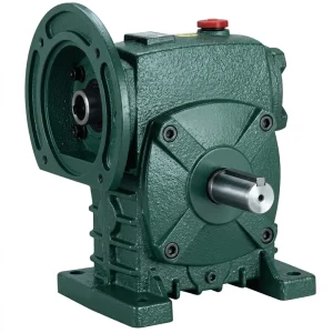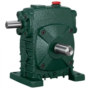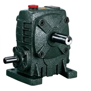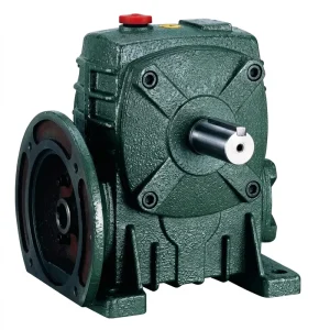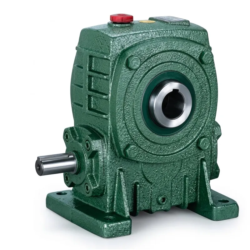
EP-WPKA 5–260 kg Single Speed Reducer
The EP-WPKA is the hollow-bore member of the WP single speed reducer family, distinguished from the WPS and WPDA designs by its through-bore input arrangement. Where the WPS takes a solid input shaft and the WPDA accepts an IEC motor flange, the WPKA is designed for applications where the driving shaft passes through the gearbox input bore rather than connecting to it via a coupling or direct motor mount. This is particularly useful in shaft-driven agricultural equipment, mill drives, and industrial machines where a continuous through-shaft topology is more practical than a stub-shaft coupling arrangement. Two shaft direction configurations — A (single output side) and B (dual output, both sides) — cover the range of installation geometries that through-shaft drives require.
The product runs from size-40 (5 kg, compact sub-kilowatt drive) through size-250 (360 kg, heavy-duty transmission for large industrial equipment), with all the standard transmission single speed reducer ratio steps available within each frame. The output shaft — a solid, taper-roller-supported shaft in the standard configuration — delivers the reduced-speed, high-torque rotation to the driven equipment.
Hollow-Bore Worm Drive Transmission
EP-WPKA 5–260 kg
Single Speed Reducer
A hollow-input-bore single speed reducer built for direct shaft-through mounting, delivering high-torque worm drive performance across 13 frame sizes in global industrial and agricultural markets.
Technical Specifications
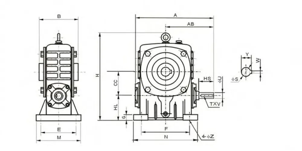
WPKA Series — Complete Dimensional Data (all dimensions in mm, weight in kg)
| Size | Ratio | A | AB | B | CC | H | HL | M | N | E | F | G | Z | Input HS | Input U | T×V | Output S | W×Y | Wt (kg) |
|---|---|---|---|---|---|---|---|---|---|---|---|---|---|---|---|---|---|---|---|
| 40 | 1/5 | 143 | 87 | 85 | 40 | 138 | 40 | 90 | 100 | 70 | 80 | 13 | 10 | 25 | 12 | 4×2.5 | 16 | 6×18.8 | 5 |
| 50 | 1/5 | 175 | 108 | 105 | 50 | 176 | 50 | 120 | 140 | 95 | 110 | 15 | 11 | 30 | 11 | 4×2.5 | 20 | 6×22.8 | 7.5 |
| 60 | 1/10 | 198 | 120 | 110 | 60 | 204 | 60 | 130 | 150 | 105 | 120 | 20 | 11 | 40 | 15 | 5×3 | 25 | 8×28.3 | 11 |
| 70 | 1/15 | 231 | 140 | 130 | 70 | 236 | 70 | 150 | 190 | 115 | 150 | 20 | 15 | 40 | 18 | 5×3 | 30 | 8×33.3 | 15.5 |
| 80 | 1/20 | 261 | 160 | 150 | 80 | 268 | 80 | 170 | 220 | 135 | 180 | 20 | 15 | 50 | 22 | 7×4 | 35 | 10×38.3 | 22 |
| 100 | 1/25 | 322 | 190 | 160 | 100 | 336 | 100 | 190 | 270 | 155 | 220 | 25 | 15 | 60 | 25 | 7×4 | 40 | 12×43.3 | 36 |
| 120 | 1/30 | 371 | 219 | 175 | 120 | 430 | 120 | 230 | 320 | 180 | 260 | 30 | 18 | 65 | 30 | 7×4 | 45 | 14×48.8 | 62 |
| 135 | 1/40 | 422 | 249 | 210 | 135 | 480 | 135 | 250 | 350 | 200 | 290 | 30 | 18 | 75 | 35 | 10×4.5 | 60 | 18×64.4 | 80 |
| 147 | 1/50 | 438 | 262 | 210 | 147 | 460 | 123 | 250 | 350 | 200 | 280 | 32 | 18 | 75 | 35 | 10×4.5 | 65 | 18×64.4 | 90 |
| 155 | 1/60 | 497 | 295 | 256 | 155 | 531 | 135 | 275 | 390 | 220 | 320 | 35 | 20 | 85 | 40 | 12×5 | 70 | 20×74.9 | 114 |
| 175 | 1/60 | 534 | 314 | 282 | 175 | 600 | 160 | 310 | 430 | 250 | 350 | 40 | 20 | 85 | 45 | 14×5.5 | 80 | 22×85.4 | 150 |
| 200 | 1/60 | 580 | 342 | 320 | 200 | 666 | 175 | 360 | 480 | 290 | 390 | 40 | 22 | 95 | 50 | 14×5.5 | 85 | 22×90.4 | 215 |
| 250 | 1/60 | 705 | 420 | 400 | 250 | 800 | 200 | 460 | 560 | 380 | 480 | 45 | 28 | 110 | 60 | 18×7 | 110 | 28×90 | 360 |
Five Key Product Advantages
What distinguishes the WPKA single speed reducer from competing transmission solutions
① Hollow Input Bore with Dual-Shaft Output
The WPKA single speed reducer's defining feature is its hollow input bore, which accepts a through-shaft from the driving machine element rather than requiring a separate coupling. This eliminates one alignment interface and reduces the total installed length of the drivetrain significantly. The shaft directions A (hollow-bore single output) and B (hollow-bore dual output) let engineers route the drive path through the gearbox in either direction, making the WPKA uniquely suited to inline shaft arrangements where a conventional single speed reducer would require an additional coupling and support bearing.
② Wide Weight Range: 5–260 kg
Frame sizes from 40 through 250 cover a unit weight spectrum from 5 kg on the smallest sub-kilowatt drive to 360 kg on the heaviest size-250, with a continuous power and torque capability that scales proportionally. A single product family covering this weight range means engineers sourcing a single speed reducer for an entire machine line can apply one specification standard from small accessory drives up to main production drives, simplifying procurement, documentation, and maintenance training.
③ Ratios 1/5 to 1/60 in Single Reduction
Like other members of the WP single speed reducer family, the WPKA covers the full standard worm gear reduction ratio range in one stage. Achieving 1/60 reduction in a single stage right-angle worm-gear speed reducer keeps the mechanical path short, limits cumulative error, and avoids the additional seals, bearings, and oil volumes that a two-stage transmission would require. The ratio range covers both brisk process drives at 1/5 and slow-speed indexing or gate drives at 1/60 without changing the mounting hardware or the driven-shaft interface.
④ Self-Locking at High Reduction Ratios
At ratios of 1/30 and above, the worm lead angle drops below the combined friction angle of the steel-on-bronze mesh, producing natural back-drive prevention. This property — absent in spur, helical, and planetary stages — makes the WPKA single speed worm gear reducer the default specification for hoist, dam gate, and inclined conveyor drives across markets in the UK, Australia, and North America where mechanical holding is a machine safety requirement, eliminating the need for a separate holding brake and its associated maintenance schedule.
⑤ ISO 9001:2015 Controlled Production
Every WPKA single speed reducer is manufactured and tested under a documented ISO 9001:2015 quality system, covering material certification, in-process dimensional verification, and final assembly inspection. Dimensional interchangeability is maintained across production batches, so replacement units from the same frame size drop into existing mounts without additional machining — a practical advantage for maintenance engineers at facilities in Germany, Canada, Brazil, and Southeast Asia who carry the WPKA single speed reducer as a running spare.
Working Principle
The WPKA single speed reducer operates on the same worm-and-wheel principle as the broader WP family. The driving shaft, passing through the hollow input bore (HS), turns the worm shaft directly via the keyway engagement. The hardened alloy-steel worm thread then meshes with the phosphor-bronze worm wheel mounted on the output shaft at 90°, converting the high-speed input rotation into low-speed, high-torque output in a single reduction stage. What is a single speed reduction gear? It is exactly this: one worm-and-wheel mesh that achieves the entire speed step in one pass, without intermediate shafting or staging.
The hollow-bore arrangement changes the input torque path in this single speed reducer compared with a solid-shaft or flanged design, but the worm gear kinetics are identical. Torque enters the worm shaft through the keyway, travels along the worm thread to the wheel teeth, and exits through the output shaft. The mesh is lubricated by the oil bath contained in the sealed cast-iron housing, with splash lubrication reaching all mesh and bearing surfaces continuously during operation. Because the input shaft is external to the gearbox rather than an integral component, worm shaft bearing loads are reduced compared with designs where the motor weight or coupling overhang acts directly on the input journal — an often-overlooked advantage of the hollow-bore single speed worm reducer format.
In shaft-direction B configuration (dual output), the output shaft exits both sides of the housing, allowing the WPKA single speed reducer to drive two loads simultaneously from a single worm gear speed reducer gearbox — for example, two parallel conveyors running at the same speed from a single drive point, or a machine where both sides of a rotating element must be driven in synchrony. This is a capability unavailable in single-output worm gearbox designs and represents one of the most distinctive application advantages in multi-axis machine architectures.

Materials & Construction
The WPKA single speed reducer housing is cast from grey iron to GG25 specification, providing the compressive strength and damping characteristics that high-torque worm drive gearbox applications require while remaining machinable to the tolerances needed for precise bore location. The hollow input bore is machined to H7 fit on the bore diameter and positioned to the worm shaft centreline using CNC boring centres that hold the centre-distance tolerance governing worm gear reduction ratio accuracy across the production batch. The T×V keyway slot is broached to DIN 6885 dimensions for full compatibility with standard shaft keys in any market.
The worm shaft is forged from 20CrMnTi alloy steel — the same grade used across the WP family — carburised and case-hardened to 58–62 HRC on the thread flanks, then cylindrically ground on the journals and thread form. This surface integrity sustains the elastohydrodynamic lubricant film needed at the sliding velocity of worm mesh contact, which runs higher in this class of single speed reducer than in spur or helical pairs. The worm wheel is centrifugally cast phosphor-bronze (CuSn12), selected for anti-seizure properties, adequate strength at elevated mesh temperatures, and the ability to conform to minor worm misalignment over the service life without accelerating flank wear on the steel worm.
Output shaft bearings are taper roller type, pre-loaded and sealed at assembly to support the combined radial and axial loads that the driven equipment places on the shaft end. Input-bore support bearings are deep-groove ball bearings sized for the radial loads from mesh forces transferred through the worm shaft. All seals are FKM (Viton) lip seals rated for continuous oil-bath service to 100 °C. External surfaces receive a two-coat primer and topcoat paint system providing 500-hour salt-spray resistance — appropriate for agricultural, water treatment, and outdoor industrial environments across the UK, Australia, Canada, and comparable markets.
Application Scenarios
Industries that specify the WPKA hollow-bore single speed reducer as their preferred worm drive solution
Shaft-Driven Agricultural Machinery
Grain augers, seed drills, and PTO-driven equipment across North American and Australian farms use the WPKA's hollow input bore to accept a through-shaft from a tractor or engine PTO. The elimination of a stub-shaft coupling reduces the part count and the alignment sensitivity at the drive connection, which is particularly valuable on mobile agricultural equipment where a solid-shaft single speed reducer would require a separate coupling hub that is susceptible to vibration.
Mill & Kiln Drives
Cement and lime kilns, ball mills, and horizontal drum dryers in European and North American heavy industry use large WPKA single speed reducer units (sizes 155–250) as the main single reduction drive stage. The hollow bore accepts the mill shell trunnion shaft directly, and the B-direction dual output configuration can drive two pinions simultaneously from a single high torque worm gearbox, distributing the torque load symmetrically around the mill circumference.
Water Infrastructure — Gates & Sluices
Irrigation headworks, dam overflow gates, and tidal barrier actuators in Australia, the UK, and the Middle East commonly use size-120 to size-200 WPKA units at ratios of 1/40 to 1/60. As a self-locking single speed reducer at these ratios, it prevents gate movement under hydrostatic head without requiring an electric holding brake, which is both a cost saving and a safety benefit at remote unmanned installations.
Dual-Output Conveyor Systems
Material handling lines that run parallel conveyors at matched speed — for example, cross-transfer tables in sawmills or sorting beds in recycling facilities — use WPKA units in B-direction configuration to synchronise two driven shafts from a single worm reducer gearbox. This approach eliminates the shaft-angle error that accumulates when two independent single speed reducer units are used on the same line.
Lifting & Hoisting Equipment
Stage rigging hoists, warehouse goods lifts, and maintenance platforms across Europe and North America rely on the inherent self-locking of high-ratio worm gear speed reducer units to hold the suspended load when the motor is de-energised. As a reliable single speed reducer for hoisting, sizes 80–155 at ratios 1/40–1/60 cover the torque range of most light-industrial hoist applications, with the hollow input bore making motor connection via a flange adaptor or a hollow-shaft coupling particularly clean and compact.
About the Manufacturer
More than a decade of focused production experience underpins every WPKA single speed reducer that leaves our facility. As a dedicated single speed reducer manufacturer, our manufacturing scope covers agricultural gearboxes, worm gear reducers, planetary gear drives, power take-off shafts, hydraulic cylinders, roller chains, and electric motors — a breadth that gives our engineering team a system-level perspective on how a speed reducer worm gearbox integrates with the surrounding drivetrain, rather than treating it as an isolated component. This understanding shows up in the bearing selection, seal specification, and oil capacity choices that are built into the standard catalogue.
Our production facility holds ISO 9001:2015 certification, governing the entire process from raw material receipt to final despatch inspection. Housing castings in ductile iron, cast iron, cast steel, precision cast steel, and cast aluminium are machined on CNC horizontal boring centres with full process traceability. Gear cutting, worm thread grinding, and heat treatment — carburising and case-hardening for worm shafts, induction hardening for output shafts — are all performed in-house, eliminating variability from sub-supplier processes. Finished assemblies are leak-tested and dimensionally verified before shipping.
Customised single speed reducer designs are available for OEM customers who need non-standard bore diameters, extended shafts, modified keyway dimensions, corrosion-resistant surface treatments, or sealed-for-life lubricant fills.
WorkShop




Related Products
Source the complete drivetrain from one facility — no integration risk, matched dimensions, single point of contact

Electric Motors
When pairing the WPKA with an electric motor, the motor shaft dimensions and rated speed must match the hollow input bore (HS) and the selected single speed reducer ratio. Our IEC motor range covers frame sizes 63 through 315 in 2-pole, 4-pole, and 6-pole configurations, with shaft diameters factory-verified against the WPKA HS bore for each frame combination. This eliminates the risk of shaft-bore interference or clearance fit errors that occur when motors and hollow-bore worm gear reducers are sourced independently.

Full-Range Worm Gearbox
The WPKA single speed reducer sits within a broader worm reducer gearbox catalogue that includes the solid-shaft WPS, flange-mount WPDA, NMRV aluminium-body reducers, and heavy-duty WD series units for very high output torques. If your application requires a different input arrangement, a smaller footprint, or a premium worm reducer configuration with extended oil capacity, the full programme covers it within the same quality and delivery framework. One-stop supply of the matched WPKA and worm gear reducer motor simplifies vendor management and reduces commissioning time.
Frequently Asked Questions
Q1. What is a single speed reduction gear, and how does the WPKA single speed reducer design differ from a standard worm reducer in Australian agricultural applications?
A single speed reduction gear is a transmission that performs the entire speed step — from high-speed input to low-speed output — in one gear mesh. In the WPKA, this is a right-angle worm-and-wheel mesh delivering ratios from 1/5 to 1/60. The hollow-bore distinction means the driving shaft passes through the gearbox input bore rather than connecting to a stub shaft end, which eliminates a coupling and the associated alignment and maintenance. In Australian grain handling and irrigation equipment, this matters because through-shaft drives are common practice — the WPKA accepts the existing shaft directly, where a standard solid-shaft single speed reducer would require a separate coupling hub, spacer, and locking element.
Q2. Which WPKA single speed reducer frame size and ratio should I specify for a dam gate drive requiring 1,200 Nm output torque at 24 rpm in a water utility project in the UK?
At 24 rpm output from a 1,450 rpm motor, the required ratio is 1/60. At this ratio, a WPKA-120 delivers sufficient output torque for most gate actuator applications in the 1,200 Nm class when driven by a 3.0–4.0 kW motor. Confirm the actual gate weight, seal friction, and hydrostatic head against the rated continuous torque for the selected frame. The 1/60 worm lead angle produces natural self-locking at this ratio, preventing gate drift under hydrostatic load when the motor is off — a property that simplifies UK water infrastructure safety compliance documentation.
Q3. How does the WPKA single speed reducer dual-output shaft configuration work, and when should I choose it over a single-output single speed worm gear reducer for a Canadian sawmill cross-transfer application?
In shaft-direction B, the WPKA output shaft exits through both sides of the housing, providing two driven ends from one worm gear gearbox. For a sawmill cross-transfer table with parallel roller shafts that must run at identical speed, a single WPKA-B driving both ends from one reducer eliminates the speed-matching error that would accumulate if two independent single speed reducer units were used. Both output ends share the same shaft, bearing set, and oil bath, so maintenance intervals are halved compared with two separate units. Specify B-direction when the load is balanced between the two output sides; if one side carries significantly more load than the other, confirm with our engineering team that the combined torque does not exceed the rated output.
Q4. What are the disadvantages of a single speed reducer in a heavy-duty worm drive gearbox used on a German cement kiln, and how does the WPKA address them?
The main disadvantages of reduction gears in worm configurations are efficiency loss (typically 70–88% for a single stage) and heat generation in the mesh. On a 24-hour cement kiln drive in Germany, this inefficiency appears as continuous motor overconsumption and elevated housing temperature. The WPKA addresses heat generation through generous oil sump sizing in the larger frames (sizes 155–250) and optimised worm lead angles that push efficiency toward the upper end of the range for each ratio. For applications where efficiency loss is unacceptable over the full production year, a bevel-helical or planetary single speed reducer should be evaluated alongside the WPKA, as both offer 95%+ efficiency at the cost of greater complexity and initial outlay.
Q5. Where can I source a customised single speed reducer based on the WPKA platform with a non-standard hollow bore diameter for OEM hoist equipment in the United States?
Customised single speed reducer variants on the WPKA frame — modified HS bore diameters, alternative keyway specifications (T×V), extended output shaft lengths, stainless shaft ends for wash-down environments, or special surface coatings — are available through our OEM programme. Provide a DXF or STEP drawing of the input shaft geometry and the required output shaft interface, along with the hoist duty cycle, suspended load, motor speed, and ambient temperature range. Our engineering team will confirm the frame size, ratio, and bore modification scope.
Q6. How do I correctly install a WPKA worm gear reducer installation on a through-shaft PTO drive in European agricultural equipment to avoid premature bearing failure?
Correct single speed reducer installation on a PTO through-shaft requires the shaft to be fully seated in the WPKA hollow bore with the keyway engaged and the set-screw or locking collar tightened to the specified torque. The shaft shoulder or spacer must locate the gearbox axially to prevent it walking along the shaft under thrust loads. Align the gearbox housing to the machine frame within 0.1 mm per 100 mm of mounting length to avoid generating bending moments on the input bore bearings — the leading cause of premature deep-groove ball bearing failure on hollow-bore worm reducers. Fill with the correct grade of EP worm gear oil to the marked level; under-filling is the second most common cause of early wear in this application type.
Editor: PXY