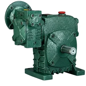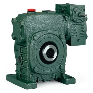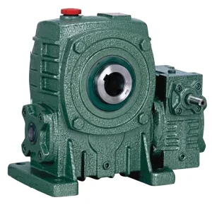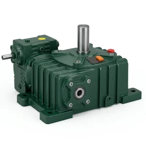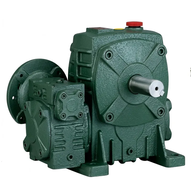
EP-WPEDA Double Speed Worm Reducer
The EP-WPEDA is a single-unit double speed reducer that incorporates two worm gear reduction stages within one rugged cast-iron housing. Engineered for continuous industrial use, it accepts input power ratings from 0.12 kW all the way through to 5.5 kW and covers an exceptionally wide weight range — from lightweight 19 kg units up to heavy-duty 470 kg configurations — making it one of the most scalable double worm gear reducer solutions currently available to OEM buyers, plant engineers, and system integrators worldwide.
Unlike a single-stage unit, the WPEDA’s cascaded worm-and-wheel design passes motion through two successive reduction meshes, which allows it to achieve high overall worm gear reduction ratios — from 1/200 to as deep as 1/900 — without the noise, complexity, or footprint penalties typically associated with multi-component parallel arrangements. The result is an exceptionally smooth output shaft rotation that supports applications where shock absorption and quiet operation are just as important as raw torque delivery.
Industrial Power Transmission · Double Speed Series
EP-WPEDA double speed worm reducer
A precision-engineered double speed worm gear reducer built for demanding B2B applications — delivering reliable torque, compact dual-reduction architecture, and the versatility that modern industrial operations depend on. When integrating a double speed worm reducer into your systems, you ensure reliable operation.
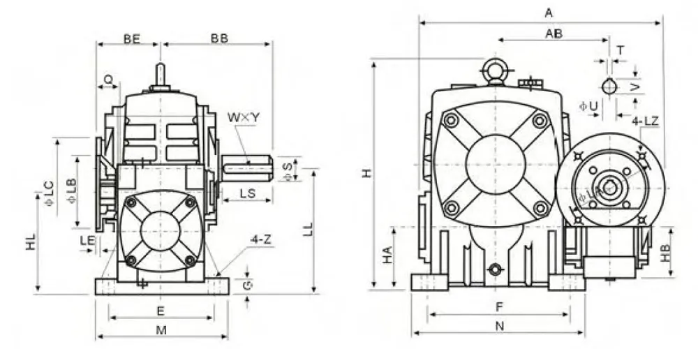
Technical Specifications — EP-WPEDA double speed worm reducer Series
Dimensional units in mm. Weight in kg. Power in kW.
| Size | Power (kW) | Ratio | A | AB | BB | BE | HL | LL | H | HA | HB | M | N | E | F | Z | Weight (kg) |
|---|---|---|---|---|---|---|---|---|---|---|---|---|---|---|---|---|---|
| 40-70 | 0.12 | 1/200 | 314 | 153 | 131 | 75 | 110 | 140 | 236 | 70 | 50 | 150 | 190 | 115 | 150 | 20 | 19 |
| 50-80 | 0.18 | 1/200 | 314 | 144 | 142 | 83 | 130 | 160 | 268 | 80 | 65 | 170 | 220 | 135 | 180 | 20 | 27 |
| 60-100 | 0.37 | 1/200 | 337 | 175 | 169 | 91 | 160 | 200 | 336 | 100 | 75 | 190 | 270 | 155 | 220 | 25 | 45 |
| 70-120 | 0.37 | 1/300 | 425 | 193 | 190 | 109 | 190 | 240 | 430 | 120 | 90 | 230 | 320 | 180 | 260 | 30 | 75 |
| 0.75 | 1/400 | 445 | 193 | 190 | 111 | 190 | 240 | 430 | 120 | 90 | 230 | 320 | 180 | 260 | 30 | 75 | |
| 80-135 | 0.75 | 1/500 | 499 | 226 | 210 | 125 | 215 | 270 | 480 | 135 | 105 | 250 | 350 | 200 | 290 | 30 | 103 |
| 1.5 | 1/600 | 499 | 226 | 210 | 125 | 215 | 270 | 480 | 135 | 105 | 250 | 350 | 200 | 290 | 30 | 103 | |
| 100-155 | 1.5 | 1/800 | 570 | 269 | 252 | 148 | 235 | 290 | 531 | 135 | 130 | 275 | 390 | 220 | 320 | 35 | 147 |
| 120-175 | 2.2 | 1/900 | 631 | 287 | 255 | 181 | 280 | 335 | 600 | 160 | 155 | 310 | 430 | 250 | 350 | 40 | 204 |
| 3.0 | 1/900 | 631 | 287 | 255 | 181 | 280 | 335 | 600 | 160 | 155 | 310 | 430 | 250 | 350 | 40 | 204 | |
| 135-200 | 3.0 | —— | 630 | 318 | 319 | 202 | 310 | 375 | 666 | 175 | 185 | 360 | 480 | 290 | 390 | 40 | 298 |
| 4.0 | —— | 630 | 318 | 319 | 202 | 310 | 375 | 666 | 175 | 185 | 360 | 480 | 290 | 390 | 40 | 298 | |
| 155-250 | 5.5 | —— | 815 | 380 | 385 | 247 | 355 | 450 | 800 | 200 | 203 | 460 | 560 | 380 | 480 | 45 | 470 |
Note: All external dimensions in millimetres. Ratios listed are representative; full ratio options vary by size. Contact us for custom ratio and mounting configurations for your double speed worm reducer.
Five Key Advantages of the EP-WPEDA double speed worm reducer
True Dual-Stage Reduction
Two worm gear meshes in series deliver ratios up to 1/900 from a single compact housing — eliminating the need for external intermediate shafts and reducing total drivetrain length by up to 35% compared to equivalent tandem single-stage setups.
Wide Power & Size Range
Input power options spanning 0.12 kW to 5.5 kW and output shaft load capacities covering 19 kg to 470 kg mean a single product family can serve light automation tasks through to heavy industrial conveying and mixing processes — simplifying your supplier count when you source this double speed worm reducer.
Five Shaft Direction Options
Configurations A through E cover every practical output orientation — left, right, vertical, and combinations thereof — so the gearbox adapts to your machine architecture rather than dictating it. This versatility makes the double speed worm reducer a highly adaptable solution across diverse OEM applications.
ISO 9001:2015 Quality Foundation
Every double speed worm reducer unit is produced under an ISO 9001:2015 certified quality management system, with dimensional inspection at key stages of casting, machining, and assembly. Buyers in the UK, South Korea, Colombia, and Brazil consistently cite our documentation and traceability as a decisive factor.
Standardised Motor Flanges
WPEDA input flanges follow M8–M12 bolt patterns across the full size range, directly accepting standard IEC motor frames from M63 to M132. This means straightforward drop-in compatibility with matched electric motors and eliminates custom adaptor plates for this double speed worm reducer.
How the double speed worm reducer Works
The double speed worm reducer operates on a cascaded double worm gear principle. The driving motor transmits rotation to a hardened worm shaft — the primary worm — which meshes at 90° with a phosphor-bronze worm wheel mounted on the intermediate shaft. This first stage provides the majority of the speed reduction, and the intermediate shaft in turn drives a second worm shaft. That secondary worm then engages a second worm wheel keyed directly onto the final output shaft.
Because each worm-and-wheel pair is self-inhibiting (the worm can drive the wheel but not vice versa when helix angles are below the friction angle), the double worm gear drive provides a natural holding action under load — a feature that eliminates the need for separate braking systems in many vertical-lift and lowering applications. This self-locking characteristic is one of the primary reasons plant engineers in Australia and Canada specifies the double speed worm reducer for inclined conveyor drives and press-feed mechanisms.
Lubrication is splash-type in smaller frames and pressure-fed in larger configurations. Thermal management is handled through the cast housing's ribbed exterior surface, which provides sufficient dissipation area at rated duty cycles for the double speed worm reducer. All shaft seals are lip-type with dust exclusion, rated for ambient temperatures typically encountered in agricultural, food processing, and general manufacturing environments.
double speed worm reducer Material Composition & Build Quality
The EP-WPEDA double speed worm reducer housing is precision cast from high-grade grey cast iron, selected for its excellent vibration-damping properties and dimensional stability under cyclic thermal loading. In larger frame sizes — specifically those handling loads above 150 kg — ductile iron or cast steel variants can be specified to meet the higher impact resistance requirements typical in heavy mining, quarrying, and recycling industry drivetrains.
The primary and secondary worm shafts are machined from carburised and case-hardened alloy steel, ground to h6 tolerance on bearing journals. This surface treatment produces a hardness gradient that provides a tough, wear-resistant outer layer (typically 58–62 HRC at the surface) while maintaining a tough core that resists shock. Worm wheels are produced in high-tin phosphor bronze, centrifugally cast for uniform grain structure before precision hobbing. This material pairing — hardened steel worm against bronze wheel — is the industry-standard combination for any high-torque double speed worm reducer and delivers the optimal balance of efficiency, long service life, and quiet running.
Bearings are deep groove ball bearings on the input shaft and tapered roller bearings on the output shaft, pre-loaded to minimise axial play. All contact surfaces are finished to Ra 0.8 µm or better. Housings are coated externally with a two-coat paint system, available in the standard green finish or in blue or white double speed worm gear reducer livery for customers requiring colour coding in safety-regulated facilities.
double speed worm reducer Application Scenarios
The double speed worm reducer EP-WPEDA is specified across a wide spectrum of industrial sectors wherever a single compact unit must achieve very high reduction ratios from a standard motor speed. Below are the most common deployment contexts encountered across our global customer base.
🌾 Agricultural Machinery
Used in auger-feed grain conveyors, irrigation pivot drives, and feed mixer drums where sustained low-speed operation at moderate torque is essential. The self-locking output shaft prevents gravity-induced back-driving when power is removed — a critical safety requirement on sloped terrain applications equipped with a double speed worm reducer.
🏗️ Material Handling & Conveyors
Inclined belt conveyor head drives, chain conveyor tail drives, and pallet transfer systems rely on the WPEDA's high reduction ratio to index loads precisely at low creep speeds. The double speed worm reducer configuration eliminates the need for a separate electromagnetic brake on most horizontal and low-angle inclined applications.
🧪 Mixing & Blending
Chemical reactors, paint mixing vessels, and polymer compounding systems require slow, steady shaft rotation with high torque and zero speed fluctuation. The two-stage reduction delivers exceptionally smooth output velocity, making it the preferred double worm gear reducer choice for viscous-media mixing in the Netherlands and German industrial markets.
♻️ Waste & Recycling Equipment
Slow-speed shredders, compactors, and baling press feed drives in recycling facilities depend on the WPEDA's tolerance for shock loading and its thermal headroom. In heavy-duty 135-200 and 155-250 size frames, units operate continuously in dusty, high-ambient-temperature sorting halls without performance degradation.
⚙️ Packaging Lines
Turntable indexers, labelling station rotators, and accumulation table drives in food and beverage packaging lines in South Korea and Colombia are a growing application segment. Here the quiet operation of the double speed worm reducer, tight dimensional tolerances, and standard IEC motor flange compatibility simplify integration into existing line layouts.
About Our Manufacturing Facility
With more than a decade of accumulated experience in mechanical power transmission engineering, our facility produces a comprehensive range of industrial components: agricultural gearboxes, double speed worm reducer systems, planetary gear drives, power take-off shafts, hydraulic cylinders, precision gears, roller chains, and electric motors. This breadth of in-house capability means we understand how a double speed worm reducer functions within a complete machine, not just as an isolated product, and that system-level perspective informs every engineering decision we make.
Our facility operates under ISO 9001:2015 certification, which governs every stage of production from raw material incoming inspection through to final assembly testing and dispatch documentation. We design and produce a wide range of gearbox assemblies — in materials including ductile iron, cast iron, cast steel, precision cast steel, and cast aluminium — as well as gears, sprockets, worm gears, pulleys, worms, shafts, and a broad catalogue of standard and non-standard mechanical parts. Customers frequently approach us as an OEM double speed worm gear reducer supplier for custom double speed worm reducer configurations, non-standard shaft configurations, and modified housing geometries that fall outside catalogue ranges.
Workshop




Related Products & System Components
A double speed worm reducer rarely operates in isolation. The two components below are the most commonly paired items and are available from the same facility, simplifying procurement, reducing lead time, and ensuring dimensional compatibility between motor shaft, input bore, and output coupling.

Electric Motors
IEC-frame induction motors sized and flanged to drop directly onto WPEDA input housings. Available in single and three-phase, B3/B5/B14 mountings, matching the full double speed worm reducer power range from 0.12 kW to 5.5 kW. Pairing a matched motor and double worm gear reducer from a single source ensures shaft, flange, and keyway compatibility without any adaptor engineering.

Worm Gearbox
Beyond the double speed worm reducer, our worm gearbox catalogue extends to single-reduction NMRV, WP, and WPS series units. If your application calls for ratios between 1/5 and 1/100 — or you need a more compact unit with a lower overall gear ratio — the single-stage range offers a one-stop solution. Explore the full worm gearbox range for sizing guidance and full dimensional data.
Frequently Asked Questions
Q1 — What is a double speed worm reducer and how does it differ from a standard single-stage worm gearbox used in industrial conveyor systems?
A double speed worm reducer — also called a double reduction worm gearbox — passes the drive through two successive worm-and-wheel meshes inside a single housing, whereas a single-stage unit uses only one mesh. This allows the double stage design to achieve overall ratios far beyond what a single stage can deliver (up to 1/900 versus roughly 1/100 maximum for single stage), making it the right choice whenever a standard motor speed needs to be reduced to a very slow, high-torque output for applications like slow-speed conveyors, mixing vessels, or indexing tables.
Q2 — Which shaft direction configuration of the EP-WPEDA double speed worm reducer works best for a horizontal conveyor drive in an Australian food processing plant?
For a horizontal conveyor with the motor mounted to one side and the conveyor drive shaft running perpendicular to the motor axis, configuration A (output to the left) or B (output to the right) is typically the cleanest solution. These keep the drivetrain compact and allow the motor to be located in a protected area away from product spillage. Configuration C — with the output shaft pointing upward — suits vertical-lift applications. A certified mechanical engineer on site should confirm which configuration minimises bending moments on the conveyor head shaft before finalising the order.
Q3 — How do I select the correct worm gear reduction ratio for a double speed worm reducer in a UK chemical processing facility?
Start with the required output speed in RPM and divide your motor's rated speed (typically 1400–1500 RPM for a 50 Hz 4-pole motor) by that figure to get the needed ratio. For example, if your mixer needs 1.7 RPM output and you have a 1440 RPM motor, you need a ratio of approximately 1/847 — meaning an 1/800 or 1/900 EP-WPEDA would be appropriate. Next, verify that the selected frame size's output torque capacity exceeds your mixer's required torque at that output speed, factoring in a 1.25 service factor for uniform load duty.
Q4 — Where can agricultural equipment integrators in Canada source a heavy duty double speed worm reducer that meets North American dimensional and documentation standards?
Agricultural integrators in Canada routinely source WPEDA units directly from ISO 9001:2015 certified manufacturing facilities that supply full documentation packages including material certificates, dimensional inspection reports, and shipment test records. When evaluating suppliers, request evidence of ISO certification, ask for sample inspection records from recent production batches, and confirm that motor flange dimensions correspond to standard IEC frame sizes (which map closely to NEMA equivalents via adaptor rings). A reputable OEM double speed worm gear reducer supplier will provide all of this as standard with each order, not as a premium add-on.
Q5 — When should a plant engineer in the Netherlands replace an existing worm speed reducer with a premium double speed worm reducer for a packaging line retrofit project?
The trigger is usually one of three conditions: (1) the current single-stage unit can no longer achieve the required low output speed without an additional external reduction stage; (2) cumulative repair costs on an ageing single-stage gearbox have begun to approach the cost of a new double-stage unit; or (3) a line speed change requires a ratio beyond the 1/100 ceiling of a single-stage worm. In all three cases, retrofitting a double speed worm reducer of the appropriate frame size — using the existing motor — is typically the lowest total-cost solution, because the WPEDA's standard motor flange accepts existing IEC motors without modification.
Q6 — What are the key maintenance steps for a double speed worm reducer operating in a high-temperature recycling facility in Brazil during continuous three-shift operation?
In high-ambient environments (above 40 °C), the primary maintenance priority is oil condition. Change the gear oil at half the standard interval — typically every 2,500 hours instead of 5,000 — and use a synthetic ISO VG 220 gear oil rather than mineral oil to maintain film strength at elevated temperatures. Check lip seal condition at each oil change, as heat accelerates elastomer hardening. Verify that the housing exterior is free of dust accumulation, which acts as insulation and raises operating temperature. For larger WPEDA frames (100-155 and above) in three-shift duty, fitting an oil-cooling circuit or external fan kit is recommended where ambient temperatures consistently exceed 45 °C.