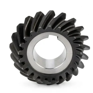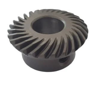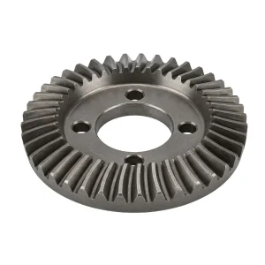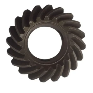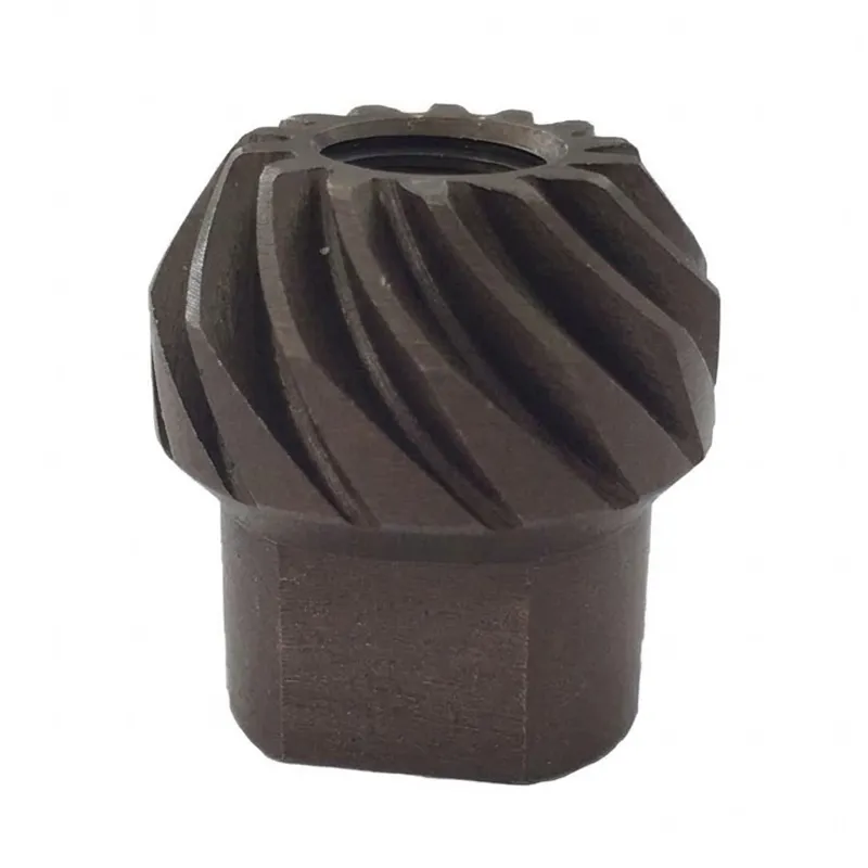
EP-Aircraft Bevel Gear
The EP-Aircraft Bevel Gear is a high-precision transmission component engineered for aerospace, military, automotive, medical, and industrial applications. With a compact Φ10 mm outer diameter and a module range of M0.15–M2.2, this series is available in eleven material variants—including Metal, Bronze, Steel, Alloy, POM, Zinc, Aluminum, Iron, Stainless, Brass, and Copper—to meet diverse load, weight, and corrosion requirements. It achieves meshing grades of JGMA 1, JIS 6, AGMA 13, DIN 6, DIN 5, and AGMA 12, ensuring exceptional accuracy for demanding drive systems. Manufactured under ISO 9001:2008 and TS16949 quality frameworks, each unit is vacuum-packed on plastic trays and shipped worldwide via DHL or UPS. Standard pressure angle is 20°, with modified angles (14.5°–25°) available through ODM/OEM customization. Samples are available upon request for fit verification before bulk production.
EP-Aircraft Bevel Gear — Precision Engineered for Demanding Drive Applications
The EP-Aircraft Bevel Gear is a high-specification precision gear designed for applications where angular power transmission must be flawless. With a compact diameter of Φ10 mm, a module range from M0.15 to M2.2, and compatibility with more than ten material variants, this bevel gear series meets the rigorous requirements found in aerospace, military systems, automotive drivetrains, and advanced medical equipment. Every gear in this series is manufactured under ISO 9001:2008 / TS16949 quality frameworks, ensuring dimensional consistency, surface finish accuracy, and long operational life. Whether you are an OEM procurement engineer in Germany sourcing a precision bevel gear for a compact actuator assembly, or a drivetrains designer in the United States specifying a bevel gear for an aircraft control linkage, this product delivers the meshing accuracy, material flexibility, and traceability your project demands. ODM and OEM customisation is fully supported, and sample availability enables fit verification before bulk production commitments.
Technical Specifications — EP-Aircraft Series
The table below outlines the verified specification parameters for the Aircraft Gear series. These figures are drawn from product inspection records and serve as the baseline reference for engineering selection. When specifying a precision bevel gear for an assembly, confirm dimensional fit against your CAD model using the Φ10 mm outer diameter as the primary envelope reference, and verify module compatibility within the M0.15–M2.2 range.
| Aircraft Gear — Full Specification | |
|---|---|
| Parameter | Value / Detail |
| Dimension (OD) | Φ10 mm |
| Module Range | M0.15 – M2.2 |
| Material Types | Metal, Bronze, Steel, Alloy, POM, Zinc, Aluminum, Iron, Stainless, Brass, Copper |
| Meshing Grade | JGMA 1 / JIS 6 / AGMA 13 / DIN 6 / DIN 5 / AGMA 12 |
| Application Fields | Automotive, Military, Aircraft, Mechanical, Industrial, Medical |
| Customisation | ODM / OEM available |
| Sample Availability | Sample available upon request |
| Packing Method | Vacuum-packed with Plastic Tray |
| Delivery Carriers | DHL & UPS |
| Certificate | ISO 9001:2008 / TS16949 |
Standard bevel gear pressure angle for this series is 20°, compliant with AGMA and DIN references. Modified pressure angles between 14.5° and 25° are available through the ODM programme for special-duty applications where tooth strength or sliding velocity must be optimised beyond the standard geometry.
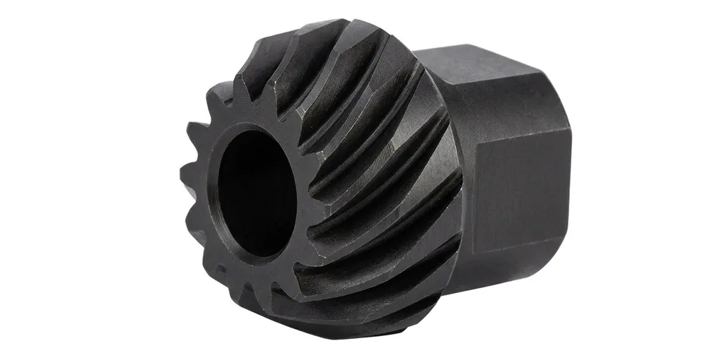
What Is a Bevel Gear and How Does It Work?
A bevel gear is a rotating machine element whose teeth are cut on a conical surface, allowing the transmission of torque and rotational motion between shafts that intersect at an angle — most commonly 90°, though other angles are achievable through custom tooth geometry. Understanding how a bevel gear works starts with the cone: each gear's pitch surface is a portion of a cone, and two mating bevel gears share a common apex point. As one gear rotates, the interlocking teeth transfer force smoothly across the shared pitch cones, redirecting rotation from one axis to another without the need for additional intermediate shafts or universal joints.
The gear ratio of a bevel gear pair is determined simply by the ratio of the tooth counts: a 20-tooth driving gear meshed with a 40-tooth driven gear produces a 2:1 reduction, halving speed while doubling torque. Straight bevel gear teeth enter mesh abruptly, making them suitable for low-speed, high-load duties where simplicity matters. Spiral bevel gears, by contrast, carry multiple teeth in simultaneous contact, which distributes load more evenly, reduces noise, and enables higher-speed service — a property heavily exploited in aerospace actuation and precision medical robotics. Zero bevel gear (Zerol®) designs represent a transitional form: curved teeth with zero spiral angle, combining the smooth engagement of spiral geometry with the ease of straight-bevel manufacturing alignment. Knowing the difference between helical and bevel gear operation is equally important: while a helical gear redirects no axis, a bevel gear's defining capability is precisely that angular change of direction, making it irreplaceable in right-angle drive trains where compact spatial packaging is paramount.
Five Key Advantages of the EP-Aircraft Series
① Multi-Grade Meshing Accuracy
Certified to JGMA 1, JIS 6, AGMA 13, DIN 6, DIN 5, and AGMA 12 meshing grades, the EP-Aircraft bevel gear provides options from tight aerospace tolerances down to robust industrial-grade fits — all within a single product family. Engineers can select the accuracy grade that matches their application's speed, load, and noise requirements without switching suppliers.
② Broad Material Portfolio
Available in Metal, Bronze, Steel, Alloy steel, POM, Zinc, Aluminum, Iron, Stainless steel, Brass, and Copper, this bevel gear can be matched precisely to the corrosion, weight, and load requirements of each application. Stainless grades suit marine and food-processing environments; aluminum cuts weight for UAV drivetrains; POM enables silent, lubrication-free operation in medical devices.
③ Certified Quality Standards
Produced under ISO 9001:2008 and TS16949 certification, every bevel gear batch follows documented process controls, incoming material inspection, and dimensional verification. For sectors like aerospace and military where traceability is mandatory rather than optional, having a certified precision bevel gear source removes a significant qualification burden from the procurement workflow.
④ ODM / OEM Customisation Ready
Non-standard shaft angles, modified bevel gear pressure angles, custom tooth profiles, proprietary bore dimensions, and surface treatments can all be engineered into the EP-Aircraft series. Prototypes and first-article samples are available before volume orders, reducing the risk of integration issues in complex assemblies. Full documentation packages are provided to support customer qualification processes.
⑤ Reliable International Logistics
Vacuum-packed on plastic trays to prevent corrosion and mechanical damage during transit, the EP-Aircraft gear ships via DHL and UPS to destinations worldwide — from automotive Tier-1 suppliers in South Korea and Japan to research institutions in the Netherlands and the UK. Consistent lead times and proper export documentation make international sourcing straightforward regardless of your region.
Material Selection for Precision Bevel Gear Applications
Selecting the right material for a precision bevel gear is not a secondary consideration — it directly determines wear life, corrosion resistance, noise profile, and weight budget. The EP-Aircraft series addresses this by offering eleven base material families, each with distinct mechanical properties suited to different operational environments.
Alloy steel and carbon steel remain the backbone of high-load precision bevel gear applications. Through carburising and case-hardening, these grades develop a hard outer surface that resists pitting and abrasion while a tougher core absorbs impact loads — precisely the profile demanded by aircraft actuator linkages and military vehicle transfer cases. Stainless steel variants resist oxidation and chemical attack, making them the preferred precision bevel gear choice for marine deck machinery, offshore equipment, and food-grade conveyor systems deployed in the Netherlands and across Northern Europe. Aluminum alloy bevel gears offer a weight reduction of approximately 65% over steel with adequate strength for UAV drivetrains, light robotics, and instrument panels where mass is at a premium. POM (acetal) gears operate without lubrication, generate minimal noise, and resist many industrial solvents — qualities that make them the dominant choice for precision gear applications in medical imaging equipment and laboratory automation in South Korea, Japan, and Australia. Brass and bronze provide excellent machinability and a natural corrosion barrier in humid environments, commonly specified in valve actuators and pump drives. The available material range means a single-source relationship is possible across an entire product family.
How to Install a Precision Bevel Gear — and Why Alignment Matters
Correct installation is as critical as the quality of the precision bevel gear itself. The defining variable is the backlash setting at the mesh point. Because bevel gear teeth taper toward the cone apex, axial positioning of both the driving and driven bevel gears must be set within tight tolerances — typically within 0.02–0.05 mm for AGMA 13 class components. The procedure for how to install a precision bevel gear follows a consistent sequence: first, mount the gear shaft bearings so they support the gear at the designed mounting distance from the cone apex; second, assemble both gears and set the axial positions using shims or threaded adjusters to achieve the specified backlash (check by rocking the driven gear with the driver locked); third, verify tooth contact pattern with marking compound — a correct pattern covers 50–70% of tooth face, centred lengthwise; fourth, torque all fasteners to specification and re-verify backlash after torquing.
Understanding the difference between helical and bevel gear applications helps clarify why a bevel gear is specified rather than a simpler alternative. A spur gear or helical gear can only transfer motion between parallel shafts. When the design requires the drive axis to turn 90° — or any other angle — a bevel gear is the technically correct solution. Bevel gear vs spur gear comparisons also reveal that bevel gears tolerate moderate misalignment better in some planes, though their conical geometry does introduce both radial and thrust forces on bearings, which must be accounted for in the bearing selection and housing design. Engineers specifying a bevel gear for the first time should confirm bearing types capable of handling combined radial-axial loads, such as tapered roller or angular-contact ball bearings, particularly for higher module sizes in the M1.5–M2.2 range.
Application Scenarios
The EP-Aircraft series is used in a wide variety of sectors where compact angular power transmission, meshing precision, and material adaptability are non-negotiable. Below are the primary precision bevel gear application domains served globally.
✈ Aerospace & Aircraft Systems
Flight control surfaces, flap actuators, landing gear retraction mechanisms, and avionics cooling fans all rely on gears to redirect motor torque within extremely constrained airframe envelopes. The small Φ10 mm envelope of the EP-Aircraft bevel gear makes it ideal for UAV control systems and light-aircraft trim actuators where gram-level weight savings accumulate into meaningful performance gains.
🛡 Military & Defence Equipment
Turret traversal drives, weapon elevation mechanisms, and ruggedised vehicle transfer cases require a precision gear that sustains performance under shock, vibration, and extreme temperature cycling. Alloy steel versions hardened to 58–62 HRC meet MIL-spec durability requirements, and the available AGMA 13 / DIN 6 accuracy grades satisfy the mesh quality stipulations found in most defence procurement standards globally.
🏥 Medical Devices & Laboratory Equipment
Surgical robots, diagnostic imaging gantries, and precision dispensing systems demand a bevel gear that operates quietly, resists sterilisation agents, and maintains positional repeatability over millions of cycles. POM and stainless steel bevel gears from this series are used in imaging equipment across medical facilities in South Korea, Australia, Canada, and the United Kingdom, where regulatory traceability through ISO certification is a baseline requirement.
🚗 Automotive & EV Drivetrains
Differential gearsets in passenger vehicles and electric drive modules use gears to split torque between left and right wheels while accommodating the speed difference through corners. The EP-Aircraft bevel gear's module range and multi-material availability allow fitment across light passenger vehicles, commercial vans, and agricultural tractors, with each application selecting the optimal gear ratio of bevel gear through tooth count selection within the same product architecture.
⚙ Industrial Machinery
Conveyor cross-drive units, packaging machine corner drives, print-head positioning mechanisms, and milling machine spindle drives all present precision bevel gear application challenges that the EP-Aircraft series is built to resolve. The broad accuracy grade selection means the same product range supplies both high-speed, noise-sensitive packaging lines and low-speed, high-torque heavy-duty conveyors without requiring separate supplier qualifications for each duty class.
🤖 Robotics & Automation
Collaborative robot wrist joints, delta robot arms, and automated guided vehicle steering modules require a compact gear maker advanced enough to achieve sub-arc-minute positional accuracy while fitting within the small joint envelopes characteristic of modern cobots. Aluminum and POM material options from the EP-Aircraft range cut joint inertia, while the JGMA 1 and AGMA 13 grades deliver the tooth accuracy needed for servo-driven closed-loop positioning systems used in factories across Brazil, Colombia, and Southeast Asia.
About Our Manufacturing Operation
With over a decade of hands-on experience in mechanical power transmission engineering, our production facility specialises in the design and manufacture of precision gear components, complete gearbox assemblies, worm gear reducers, planetary drive units, power take-off shafts, hydraulic cylinders, sprockets, pulleys, chains, and industrial motors. Our factory holds ISO 9001:2015 certification, which governs every stage of the production process from raw material receipt through to final inspection and shipment preparation.
We design and produce a comprehensive catalogue of industrial and agricultural gearboxes and assemblies using ductile iron, cast iron, cast steel, precision cast steel, and cast aluminum as primary construction materials. Standard mechanical components — gears, sprockets, worm gears, pulleys, worms, and shafts — are manufactured alongside non-standard parts engineered to customer drawings, making us a genuine one-stop supplier for global industrial equipment builders.
WorkShop




Related Products — Complete Drive System Compatibility
A precision gear rarely operates in isolation. In most drive architectures, it works alongside parallel-shaft gearing stages and rack-and-pinion elements to complete the full motion pathway. We manufacture all these complementary components in-house, giving you genuine single-source supply with guaranteed cross-component fit and unified quality documentation.
Double Helical Gear
Paired with a bevel gear at the input or output stage of a gearbox, a double helical gear (herringbone gear) eliminates the net axial thrust force that single helical stages introduce, enabling higher torque density and smoother operation in high-speed parallel-shaft drive sections. The combination of a gear for angular redirection and a double helical gear for the main reduction stage is common in heavy-duty industrial gearboxes and large-scale power generation equipment.

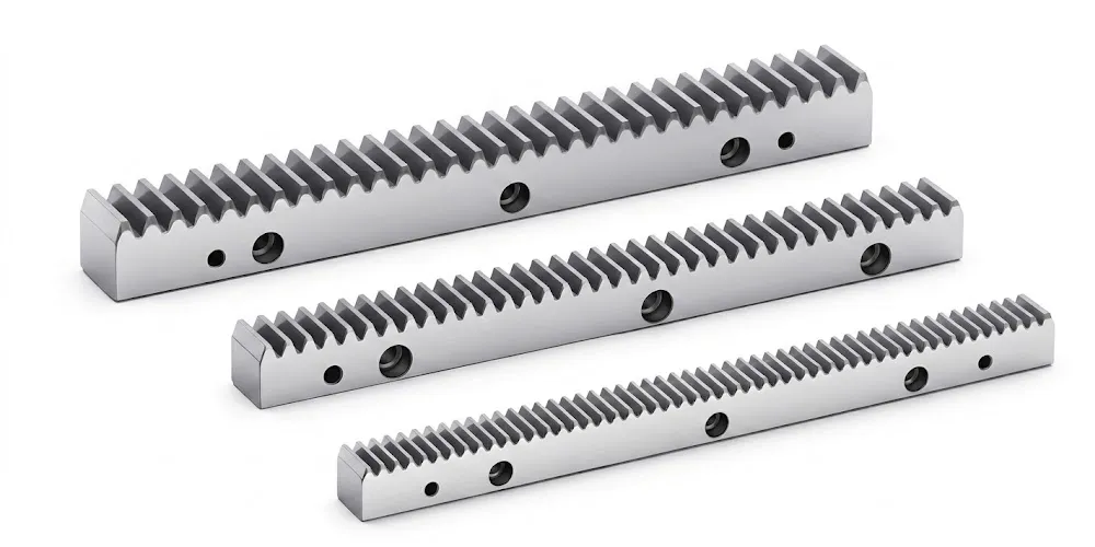
Gear Rack
Gear racks convert the rotational output of a bevel gear drive into precise linear displacement. In gantry robots, CNC machine axes, and automated warehouse systems, the gear rack interfaces with a pinion gear driven by the bevel gear output shaft, producing controlled linear positioning with the force multiplication benefits of the bevel gear reduction stage upstream. Matching rack pitch to the pinion module is straightforward when both components come from a single supplier with unified production standards.
Trade & Delivery Information — Gear Products
The following trade terms, lead times, and MOQ policies are specifically mapped to gear-type products (gears, pinions, worm gears, bevel gears, helical gears, ground gears) based on our general trading framework. Only clauses directly referencing gear products have been extracted from the full terms library.
Lead Time
Based on the standardisation level, machining complexity, and processing requirements of gear products:
| Gear Products — Lead Time Reference | |
|---|---|
| Product Category | Estimated Lead Time |
| Standard Transmission Gears | 10–25 working days |
| Standard Gears + Simple Processing | 15–35 working days |
| Custom Machined Gears | 20–45 working days |
| High-Precision / Heat-Treated Gears | 30–60 working days |
Trade Types
Recommended Incoterms based on product volume, weight, value, and urgency for gear products:
| Gear Products — Recommended Trade Terms | |
|---|---|
| Product Type | Recommended Terms |
| Standard Gears | EXW / FOB / CIF / DAP |
| Custom / OEM Gears | EXW / FOB / CIF / DAP |
FCA, CFR, CPT, CIP and DDP terms are also available upon specific request and subject to negotiation.
MOQ
Minimum order quantities for gear products are determined by product type, material, processing requirements, and batch size:
| Gear Products — MOQ Guidelines | |
|---|---|
| Product Category | MOQ Policy |
| Custom Gears | MOQ depends on drawing, material, tolerance, machining process and batch size. |
| Heat Treatment / Surface Treatment | Special processing may be limited by process batch size. |
General Terms
The following baseline terms apply to all gear product orders:
| General Trading Terms | |
|---|---|
| Term | Policy |
| MOQ Principle | Flexible based on product type and order value. |
| Sample Policy | New customers may apply for 1–5 samples where suitable. |
| Mixed Orders (Consolidation) | Combination of different models supported; total order value should reach approximately USD 1,500. |
| Small Orders | 1–2 pcs orders supported, but unit price may be relatively higher. |
| Overall Delivery Time | Standard parts: 10–25 working days | Custom components: 20–45 working days | Project equipment: 45–120 working days |
| Overall Trade Terms | EXW, FOB, CIF, DAP supported as standard; FCA, CFR, CPT, CIP and DDP available upon specific negotiation. |
Frequently Asked Questions — EP-Aircraft Bevel Gear
Editor: PXY