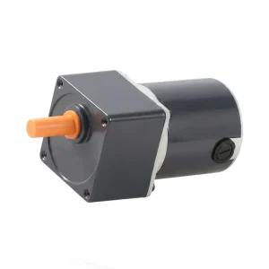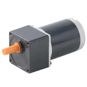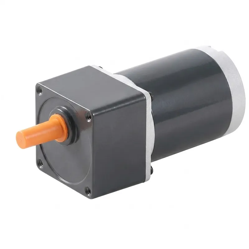
EP-15-30W DC Motor — Mid-Power Permanent Magnet Series (20W & 25W)
The EP-15-30W series delivers a practical step up in output torque relative to smaller 6–10 W motor families while remaining compact enough for space-constrained machine designs. The 20 W model (K3GN20-90□) operates on a 90 V DC supply and achieves 2800 RPM under rated load with a shaft torque of 0.70 kg·cm — a useful match for 90 V DC bus systems common in factory-supplied rectified mains applications across European and North American industrial installations. The 25 W models (K3GN25-12□ and K3GN25-24□) extend voltage choice to 12 V and 24 V DC, serving battery-powered platforms and low-voltage automation systems where the higher torque of 0.80–0.87 kg·cm at load is required from a portable or DC-bus-powered supply.
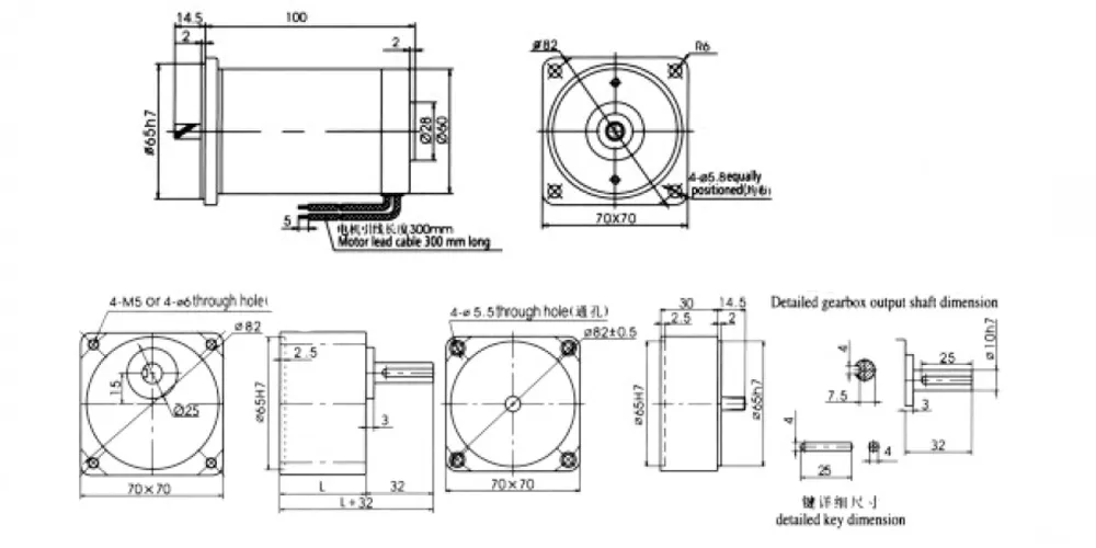
All three models share a 70×70 mm mounting flange with 4×M5 or 4×ø6 through holes, a motor body diameter of ø82 mm, and a consistent 3000-hour brush life rating. Motor weight is 1.0 kg across the series, giving system designers a predictable mass budget when calculating mounted inertia or bracket load capacity.
EP-15-30W DC Motor — Mid-Power Permanent Magnet Series (20W & 25W)
The EP-15-30W is a mid-power permanent magnet dc motor series covering 20 W and 25 W output levels across 12 V, 24 V, and 90 V supply voltage options. Housed in a 70×70 mm face-mount body, this dc motor series steps up from compact light-duty designs to deliver the higher shaft torque and sustained load capacity demanded by feeding equipment, medical drives, automated production machinery, and battery-powered mobile platforms across global industrial markets.
Motor Characteristics — EP-15-30W Series
The table below covers all three dc motor models in the EP-15-30W series. No-load parameters represent free-running conditions at rated voltage; load parameters are measured at rated output power. All models carry a 3000-hour brush life rating under normal duty conditions. Scroll horizontally on mobile to view all columns.
| 模型 | Voltage (V) | Power (W) | No-load Speed (RPM) | No-load Current (A) | Load Speed (RPM) | Torque (kg·cm) | Load Current (A) | Brush Life (H) | Weight (kg) |
|---|---|---|---|---|---|---|---|---|---|
| K3GN20-90□ | 90 | 20 | 3150 | 0.2 | 2800 | 0.70 | 0.50 | 3000 | 1.0 |
| K3GN25-12□ | 12 | 25 | 3300 | 1.0 | 3000 | 0.80 | 3.50 | 3000 | 1.0 |
| K3GN25-24□ | 24 | 25 | 3200 | 0.5 | 2800 | 0.87 | 1.60 | 3000 | 1.0 |
Torque at rated load in kg·cm. All electrical values at rated voltage. Brush life under normal duty operating conditions.
Gearbox Specifications — 3GN Series
The 3GN-series spur gearboxes mount directly to the 70×70 mm motor flange and extend the output speed and torque range of the EP-15-30W dc motor across a wide application spectrum. Three gearbox length options cover low, mid, and high ratio ranges; an additional intermediate gearbox (3GN10X) handles a specific intermediate ratio stage. All dimensions in mm; weight in kg.
| Gearbox Type | Reduction Ratio Range | Length L (mm) | Weight (kg) |
|---|---|---|---|
| 3GN Spur | 3GN3K–GN15K | 32 | 0.38 |
| 3GN Spur | 3GN18K–GN50K | 42 | 0.47 |
| 3GN Spur | 3GN60K–GN200K | 42 | 0.52 |
| Intermediate (3GN10X) | 3GN10X | 30 | 0.38 |
Allowable Torque — 3GN□K Gearbox with K2D10-24□ (Low-Ratio Range: 3–50)
| 模型 | 範圍 | 3 | 3.6 | 5 | 6 | 7.5 | 9 | 10 | 12.5 | 15 | 18 | 20 | 25 | 30 | 36 | 40 | 50 |
|---|---|---|---|---|---|---|---|---|---|---|---|---|---|---|---|---|---|
| K2D10-24□ | Output Speed (r/min) | 1067 | 889 | 640 | 533 | 427 | 356 | 320 | 256 | 213 | 178 | 160 | 128 | 107 | 89 | 80 | 64 |
| Allow. Torque (N·m) | 0.21 | 0.25 | 0.34 | 0.41 | 0.52 | 0.62 | 0.69 | 0.86 | 1.03 | 1.24 | 1.24 | 1.56 | 1.87 | 2.24 | 2.49 | 3.11 | |
| Allow. Torque (kgf·cm) | 2.1 | 2.6 | 3.5 | 4.2 | 5.3 | 6.3 | 7.0 | 8.8 | 10.5 | 12.6 | 12.6 | 15.9 | 19.1 | 22.8 | 25.4 | 31.7 |
Allowable Torque — 2GN□K Gearbox (High-Ratio Range: 60–200)
| 模型 | 範圍 | 60 | 75 | 90 | 100 | 120 | 150 | 180 | 200 |
|---|---|---|---|---|---|---|---|---|---|
| K2D10-24□ | Output Speed (r/min) | 53 | 43 | 36 | 32 | 27 | 21 | 18 | 16 |
| Allow. Torque (N·m) | 3.38 | 4.22 | 4.90 | 4.90 | 4.90 | 4.90 | 4.90 | 4.90 | |
| Allow. Torque (kgf·cm) | 34.5 | 43.1 | 50 | 50 | 50 | 50 | 50 | 50 |
Allowable torque caps at 4.90 N·m (50 kgf·cm) for ratios 90–200 in the 2GN□K high-ratio gearbox due to gearbox structural limits. Gearbox model 2GN□K used for ratios 60–200.
Five Key Advantages of the EP-15-30W DC Motor
① Higher Torque at Moderate Power Input
At 20–25 W input, the EP-15-30W series produces shaft torques of 0.70–0.87 kg·cm at rated load — significantly above the 0.35 kg·cm delivered by 10 W motors in the same family. This torque headroom is directly useful in applications where load friction, acceleration inertia, or intermittent overload conditions require a motor with genuine sustained torque capacity beyond its nameplate power rating.
② 90V Model for Industrial DC Bus Systems
The K3GN20-90□ operates at 90 V DC — a common bus voltage in factory-supplied drives and CNC machine auxiliary circuits. At 90 V, rated current drops to only 0.50 A, which allows direct operation from small rectified mains power supplies without a high-current DC driver stage. This makes the 90 V model the preferred choice in European and North American industrial panel-build environments where 90 V DC speed controllers are already standardized.
③ Wide Gearbox Ratio Coverage (3:1 to 200:1)
The 3GN-series spur gearbox extends the usable output speed range from 16 RPM at 200:1 up to 1067 RPM at 3:1. With an allowable gearbox torque reaching 3.11 N·m at a 50:1 ratio from just 24 V supply, this high torque dc motor and gearbox combination covers the majority of slow-speed, high-torque drive requirements in light industrial automation without additional torque multiplication stages.
④ Standardized 70×70 mm Mounting Interface
The fixed 70×70 mm flange face with 4-bolt pattern creates a standardized mounting interface shared across the entire 3GN motor-gearbox family. Machine frames built to this mounting standard accept any motor-gearbox ratio configuration as a drop-in change — simplifying product variant management and field retrofitting without mechanical redesign when application requirements change.
⑤ Bidirectional Operation — Simple Polarity Reversal
Rotation direction in this permanent magnet dc motor series switches by reversing polarity on the supply leads — red positive for CW, black positive for CCW as viewed from the output shaft. An H-bridge driver or a DPDT relay provides this function with a single logic signal, making bidirectional dc motor drive implementations straightforward without specialized servo electronics or encoder feedback in open-loop applications.
DC Motor Working Principle — What Makes This Series Tick
這 dc motor working principle governing the EP-15-30W series is the same electromagnetic foundation that underlies all brushed permanent magnet motors: current-carrying armature conductors in a static magnetic field experience a force (Lorentz force) that produces shaft rotation. In a permanent magnet design, the stator field is fixed by the magnets themselves — there are no field windings to excite, adjust, or supply current to separately. This simplification means that speed regulation under varying load is handled entirely by the relationship between applied voltage, armature resistance, and back-EMF. As load torque increases, armature current rises and speed drops slightly — a characteristic captured in the difference between no-load and rated-load speeds in the specification table.
The commutator and brush assembly reverses armature current in each coil at the moment it crosses the magnetic neutral axis, ensuring that the resultant torque always acts in the same direction regardless of shaft position. In the K3GN25 models, the commutator is machined from electrolytic copper bar and assembled to tight radial runout tolerances. Brush contact pressure is set at the factory to deliver consistent electrical contact without generating excessive friction or brush wear rate. The 3000-hour brush life rating in this series reflects an operating current well within the thermal capacity of the commutator and brush grade selected.
At the 20 W and 25 W level, thermal management of the armature begins to play a more significant role than in smaller motors. The ø82 mm aluminum housing provides greater surface area for passive heat dissipation than smaller-diameter designs, and the armature windings are vacuum-impregnated with Class B or F insulation varnish that both improves thermal conductivity from winding to housing and locks the conductors against vibration-induced movement. Understanding these design details is important when specifying the motor for high duty-cycle applications — a motor running at 80%+ duty continuously in a warm enclosure will run hotter than the same motor in an intermittent-duty application, and enclosure ventilation should be considered accordingly.
Construction & Materials
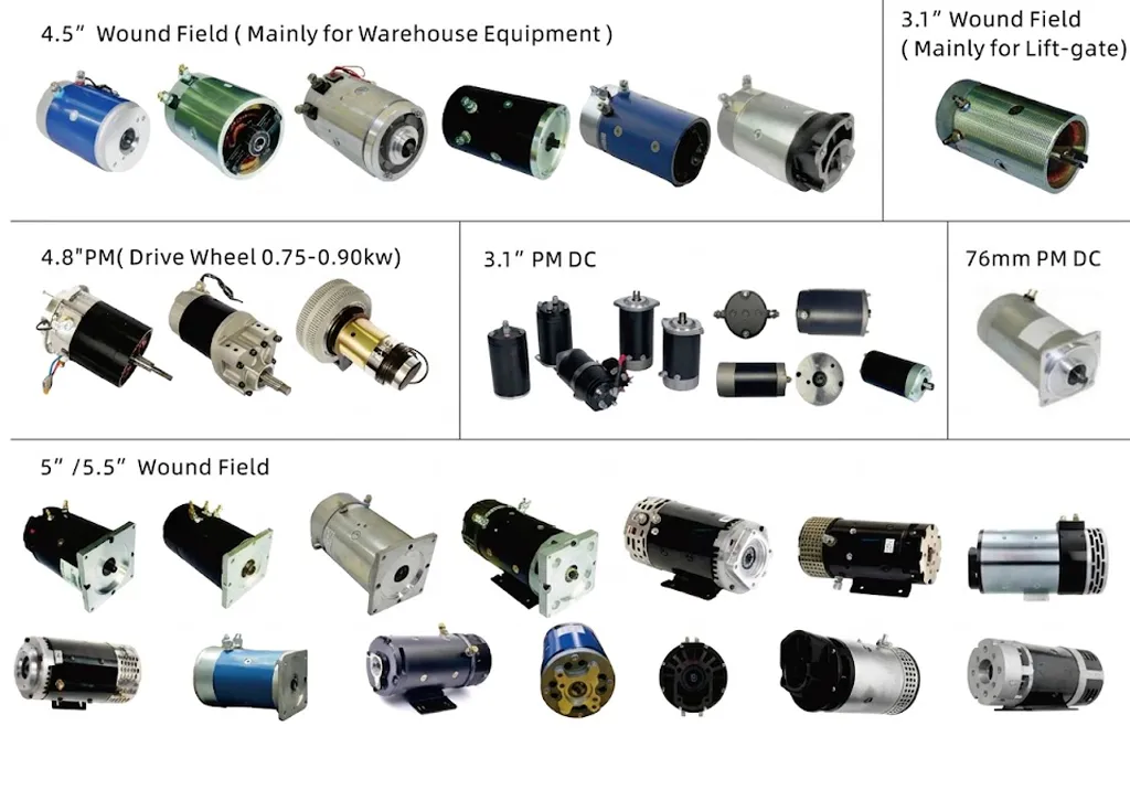
At the 20–25 W power level, component material selection in a dc electric motors design directly affects thermal performance, service life, and mechanical integrity under sustained operation. The EP-15-30W series uses a die-cast aluminum alloy housing of ø82 mm diameter — larger than the ø55 mm body used in the 6–10 W class, providing substantially more surface area for passive convection cooling of the armature heat load. The housing is precision-machined at both the motor front flange register and the rear bearing seat to maintain concentricity between motor shaft and mounting face, which matters when connecting gearboxes or output couplings that must run true to minimize bearing side loads.
The stator field is established by high-energy bonded ferrite or sintered NdFeB permanent magnets depending on the model voltage and torque specification. Sintered magnets provide higher flux density and allow a smaller magnetic circuit for a given torque output — important in keeping the ø82 mm motor body as compact as possible relative to its output. Armature windings use enameled copper wire wound to precise turn count and layer pattern specifications, then vacuum-impregnated with thermal-class B or F varnish. This varnish treatment consolidates the winding into a solid thermal mass that conducts heat to the housing more effectively than air-gap separated wire bundles, reducing peak conductor temperature under high duty cycle operation.
The commutator is produced from hard electrolytic copper, with segments precision-ground to within ±0.01 mm runout after assembly. Carbon-graphite brushes are grade-selected to match the commutator copper and the current density at rated load — a critical engineering choice because brush grade determines both the steady-state contact resistance (which affects speed regulation) and the wear rate (which determines service interval). The ø25H7 output shaft is manufactured from alloy steel, induction-hardened at the bearing journals, with a parallel keyway ground to ISO tolerance for positive torque transmission to attached components.
Application Scenarios
The combination of mid-range power, three voltage options, and a comprehensive gearbox ratio catalogue makes the EP-15-30W dc motor series suitable for a wide spectrum of light-to-medium industrial and commercial drive applications. Below are the sectors where this series most commonly serves as the primary drive component.
CNC Machine Auxiliary Drives
Coolant valve actuators, tool change positioning motors, and workpiece clamping drives on CNC turning and milling centers in European and North American machine shops frequently specify the K3GN20-90□ model because its 90 V operating voltage matches the DC bus commonly used in CNC auxiliary circuits. At 0.50 A rated current, it operates comfortably on standard 90 V DC drive modules without requiring oversized current capacity.
Automated Vending & Dispensing Systems
Product delivery mechanisms, spiral dispensing coils, and gate actuators in vending machines and automated retail kiosks across Southeast Asia and Australia use 24 V dc motors for their compatibility with standard 24 V SMPS supplies. The K3GN25-24□ paired with a mid-ratio 3GN gearbox delivers the precise low-speed rotation needed for reliable product dispensing without overshoot or jamming.
Mobile Robotics & AGV Platforms
Steering actuators, pan-tilt camera mounts, and gripper drives on Automated Guided Vehicles (AGVs) in South Korean and Japanese manufacturing facilities use 12 V and 24 V high torque dc motor units drawing from vehicle batteries or onboard power packs. The K3GN25-12□ at 3.50 A rated load current is within the output capacity of standard 12 V battery systems used in small AGV platforms, delivering reliable bidirectional positioning through simple H-bridge control.
Medical Rehabilitation Equipment
Motorized joint actuators in physiotherapy equipment, exoskeleton components, and active orthotic devices in Canadian and European medical device manufacturing require reliable, compact permanent magnet dc motor units that meet low-voltage safety requirements while delivering the sustained torque needed to assist or resist patient limb movement. The EP-15-30W series at 24 V provides this combination in a verified, factory-tested format with documented brush life performance.
Textile Machinery Feed Drives
Yarn feed tensioners, warp let-off drives, and winding traverse mechanisms in textile production plants across France, Turkey, and Southeast Asia use 24 V dc motor drive systems for their controllable speed-torque behavior during production speed ramp-ups and slowdowns. The linear speed-voltage characteristic of the permanent magnet design makes tension control straightforward without closed-loop speed feedback in many applications.
Agricultural Precision Metering
Variable-rate seed metering units, liquid fertilizer pump drives, and crop sprayer section control actuators on precision agriculture equipment in Australian and Brazilian operations use 12 V dc electric motors powered directly from tractor electrical systems. The K3GN25-12□ draws within the fused circuit limit of standard agricultural wiring harnesses, and its high-ratio 2GN gearbox option allows the very slow, accurate shaft speed required for calibrated variable-rate application systems.
About Our Manufacturing Operation
With over a decade of focused production experience in mechanical and electrical power transmission, our engineering team brings genuine technical depth to every product we supply. Our manufacturing range covers agricultural gearboxes, worm gear reducers, planetary gear drives, power take-off shafts, hydraulic cylinders, gears, chains, and motors — produced entirely in-house under ISO 9001:2015 quality management certification. This breadth of capability means customers sourcing dc motors, matched gearboxes, and associated mechanical components can do so from a single manufacturing partner rather than coordinating across multiple suppliers.
We design and produce standard and non-standard gearboxes and mechanical assemblies in ductile iron, cast iron, cast steel, precision cast steel, and cast aluminum — along with gears, sprockets, worm gears, pulleys, worms, shafts, and custom mechanical parts to OEM specifications. Customers in the UK, Australia, Canada, Brazil, France, South Korea, and Southeast Asia rely on our factory as a technically capable and responsive supply source for high torque electric motor and drive system components, backed by engineering support and efficient export logistics.
工作坊




Related Products
The EP-15-30W dc motor integrates directly with other drive system components from our manufacturing range. Sourcing matched components from a single factory simplifies quality accountability, reduces procurement lead time, and ensures dimensional compatibility across all mating interfaces.
Full DC Motor Range
The EP-15-30W series sits within a broader dc motor catalogue that spans compact 6 W units through higher-power motors suitable for medium industrial drives. Whether you need a small dc motor for a lightweight instrument application or a higher-power high torque electric motor for a more demanding drive, our range provides scalable options within consistent dimensional and quality standards — including brushed, bldc motor, and specialty servo configurations depending on the specific duty cycle and control requirements of your application.

Worm Gearbox Range
For applications where the 3GN spur gearbox series reaches its torque limit and a higher structural output torque capacity is needed, our worm gearbox range offers frame sizes from 40 mm to 250 mm center distance with output torques from fractional to several hundred N·m. Worm gearboxes are typically driven by larger AC or DC motors but function as a natural complementary product alongside dc motor drive systems where slow output speed, self-locking capability, or right-angle shaft direction change is required in the same drive train as a DC motor-based prime mover.

常見問題解答
編輯:PXY