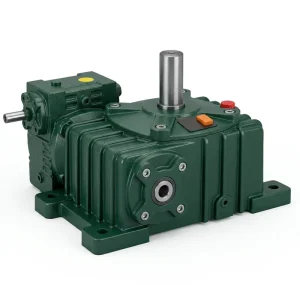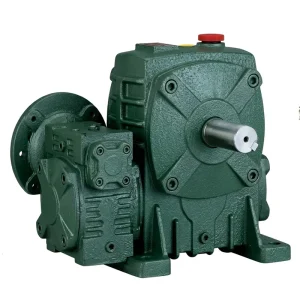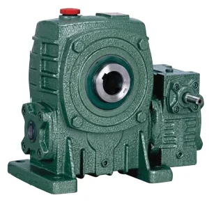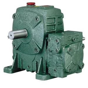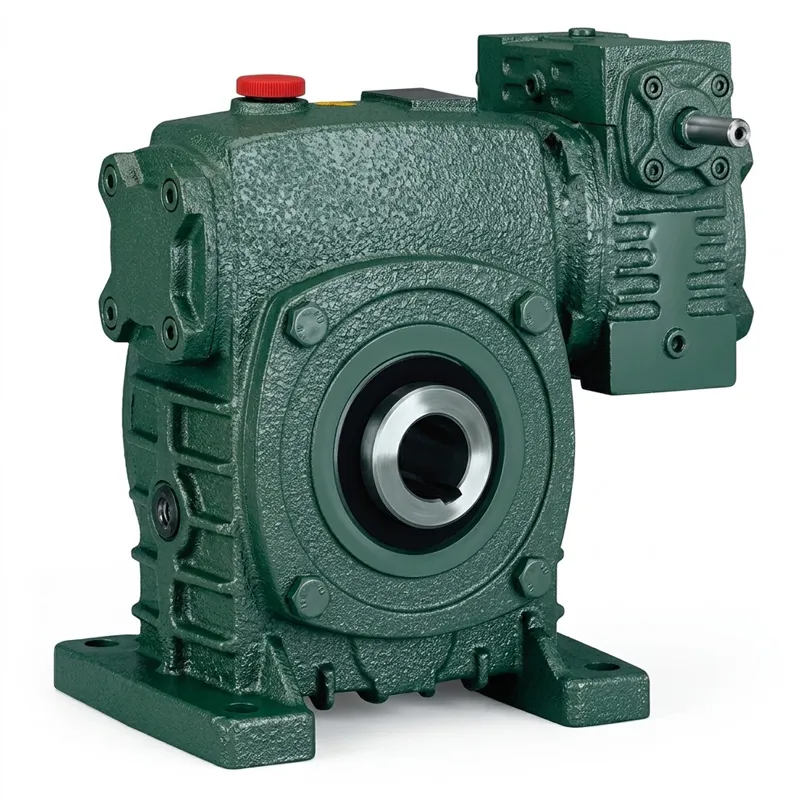
EP-20–462 kg WPEKS Double Speed Reducer
The EP-WPEKS is a foot-mounted, hollow-bore double speed reducer built around a worm-and-wheel pair that delivers reliable torque multiplication across a broad range of demanding industrial and agricultural applications. With input power ratings from 0.12 kW up to the 5.5 kW range and unit weights spanning 20 kg to 462 kg, this series covers an exceptionally wide performance envelope within a mechanically consistent housing geometry. The hollow bore output shaft — a distinguishing structural feature of the WPEKS relative to the solid-shaft WPEDS — allows the driven shaft to pass directly through the reducer, eliminating couplings and reducing total drivetrain length in cramped machine frames.
Reduction ratios from 1/200 through 1/900 are available across the size range, giving specifying engineers genuine flexibility to match output RPM to process requirements without resorting to secondary chain or belt reduction stages. All units ship pre-filled with mineral gear oil at the correct level for horizontal mounting, and alternative lubrication grades for vertical mounting or elevated ambient temperature environments are documented in the installation guide. Three shaft direction configurations — A, B, and C — cover the most common input-to-output angular arrangements encountered in conveyor, mixer, and positioning machine designs worldwide.
EP-WPEKS Series Double Speed Reducer
EP-WPEKS Double Speed Reducer
Hollow-Bore Worm Gear Drive · 20–462 kg · Shaft Configurations A / B / C · Global Industrial Supply
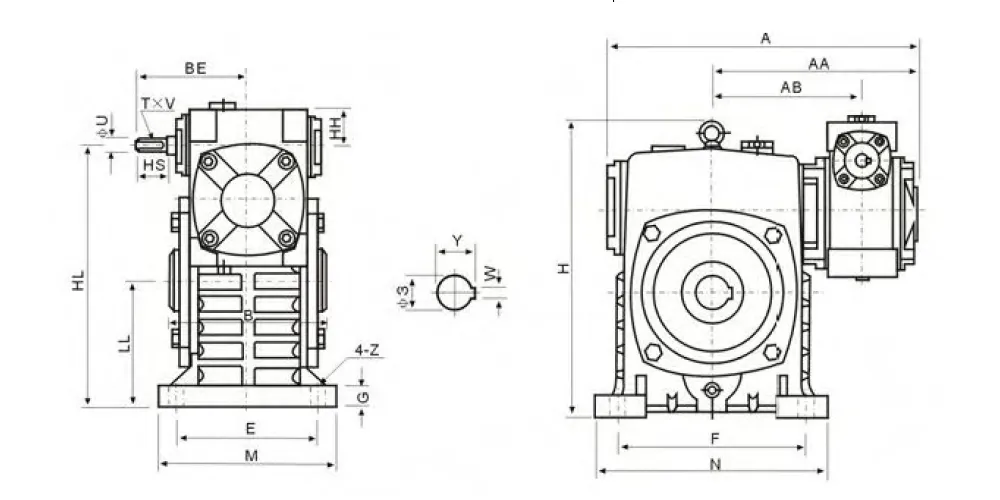
Technical Specifications — EP-WPEKS Double Speed Reducer
| Double Speed Reducer Size | Ratio | A (mm) | AA (mm) | AB (mm) | B (mm) | BE (mm) | HL (mm) | H (mm) | M (mm) | N (mm) | Input T×V | Output W×Y | Weight (kg) |
|---|---|---|---|---|---|---|---|---|---|---|---|---|---|
| 40–70 | 1/200 | 286 | 195 | 153 | 130 | 87 | 215 | 238 | 150 | 190 | 4×2.5 | 8×33.3 | 20 |
| 50–80 | 1/300 | 297 | 197 | 144 | 150 | 108 | 250 | 273 | 170 | 220 | 4×2.5 | 10×38.3 | 27 |
| 60–100 | 1/400 | 363 | 231 | 175 | 160 | 120 | 310 | 334 | 190 | 270 | 5×3 | 12×43.3 | 44 |
| 70–120 | 1/500 | 408 | 256 | 193 | 175 | 140 | 370 | 423 | 230 | 320 | 5×3 | 14×48.8 | 73 |
| 80–135 | 1/600 | 471 | 298 | 226 | 210 | 160 | 430 | 482 | 250 | 350 | 7×4 | 18×64.4 | 101 |
| 100–155 | 1/800 | 555 | 354 | 269 | 256 | 190 | 490 | 541 | 275 | 390 | 7×4 | 20×74.9 | 144 |
| 120–175 | 1/900 | 598 | 379 | 287 | 282 | 219 | 555 | 600 | 310 | 430 | 7×4 | 22×85.4 | 201 |
| 135–200 | 1/200–1/900 | 662 | 425 | 318 | 320 | 256 | 625 | 677 | 360 | 480 | 10×4.5 | 22×90.4 | 293 |
| 155–250 | 1/200–1/900 | 795 | 510 | 380 | 400 | 295 | 755 | 824 | 460 | 560 | 12×5 | 28×116.4 | 462 |
Dimensions are for reference only. Confirm dimensional drawings with the engineering team before integrating into machine designs. Input shaft keyway T×V and output bore W×Y values shown above; additional flange dimensions (HS, U) available on request.
Five Key Advantages of the EP-WPEKS Double Speed Reducer
① Hollow Bore Output — Zero-Coupling Assembly
The through-bore output shaft design lets the driven machine shaft slide directly inside the reducer housing, removing shaft couplings from the drivetrain entirely. This reduces the number of precision-alignment steps during installation, shortens the machine's overall axial length, and eliminates a common source of vibration and wear in conventional solid-shaft worm reducer setups.
② Broad Ratio Range — 1/200 to 1/900
A single standardised housing series spans reduction ratios from 1/200 through 1/900, meaning buyers can select the gear worm reducer ratio that fits their exact process speed without ordering a bespoke unit. This breadth is particularly valuable for OEM machine builders who supply equipment to multiple markets with different electrical supply frequencies and therefore different motor synchronous speeds.
③ Three Shaft Configurations for Flexible Integration
Shaft direction variants A, B, and C accommodate the most common worm drive input-output geometries without additional bevel stages or right-angle adaptors. Variant B positions the hollow bore output collinear with the input worm centre axis, making it ideal for space-restricted installations where the motor and driven load must share a common plane. This is a measurable installation-time advantage on assembly lines in the UK, Netherlands, and South Korean automation sectors.
④ ISO 9001:2015 Certified Manufacturing
Every unit produced under this model series is manufactured within an ISO 9001:2015 certified quality management framework, covering raw material traceability, dimensional inspection at each machining stage, final assembly verification, and documentation release. For buyers sourcing a replacement double speed worm gear reducer for operating equipment, this certification provides assurance that dimensional interchangeability is maintained across production batches.
⑤ Self-Locking at High Reduction Ratios
At ratios above approximately 1/300, the worm lead angle falls below the friction angle of the worm-wheel interface, making the drive inherently non-back-drivable under static load. Vertical conveyor systems, scissor-lift platforms, and gate actuators benefit directly from this passive holding characteristic, removing the need for brake motors or ratchet mechanisms in many designs and reducing total build cost at the system level.
Working Principle of the WPEKS Double Worm Gear Drive
At its core, the WPEKS Double Speed Reducer operates on the same fundamental worm-and-wheel transmission principle that has defined precision low-speed industrial drives for over a century—but its hollow-bore architecture changes how that principle is physically packaged. Power enters through the input worm shaft, a hardened alloy-steel helix precision-ground to DIN or equivalent accuracy. As the worm rotates, its threads engage consecutive teeth on the larger bronze worm wheel, converting high-speed rotational motion into proportionally slower, proportionally stronger torque at the output.
The worm wheel is keyed or press-fitted to a hollow output sleeve rather than a solid shaft. This sleeve is supported within the housing on a pair of tapered roller bearings arranged in a face-to-face configuration that controls both radial runout and axial float simultaneously. The driven machine shaft—a conveyor drum axle, a mixing paddle shaft, a screw conveyor tube—slides into the hollow bore and is secured by a key or interference fit, depending on the design torque level. In effect, the reducer becomes part of the shaft rather than something bolted alongside it.
This geometry tightens the load path between motor and process: the torque-transmitting interface is at the bore surface of the output wheel, directly concentric with the driven shaft, without the eccentricity that flexible couplings introduce. The result is lower vibration amplitude at the motor flange, longer bearing life in the connected motor, and more accurate speed control when the reducer is paired with a variable-frequency drive as part of an electrical motors double speed worm gear reducer assembly. Lubrication is maintained by a splash-fed oil reservoir in the lower housing, with oil level sight glasses and fill/drain ports positioned for each of the three mounting orientations.
Double Speed Reducer Materials & Build Quality
The housing body of the EP-WPEKS Double Speed Reducer is cast from HT250 grey cast iron, selected for a combination of excellent vibration damping, pressure-tight casting integrity, and machinability that allows the tight bearing-bore tolerances required for worm gear centre-distance accuracy. For specialised applications involving higher shock loading—heavy-duty worm drive gearbox duties in quarrying, demolition equipment, or recycling plant drives—nodular iron EN-GJS-500-7 is available as an upgraded housing material without changes to the external mounting geometry or bolt pattern.
The worm shaft is machined from 20CrMnTi carburising steel, case-hardened to 58–62 HRC at the flank surfaces while maintaining a tough, ductile core to absorb shock loads. After heat treatment, the worm profile is ground on a CNC generating grinder to produce a tooth-surface roughness of Ra ≤ 0.8 µm. This finish level is what allows hydrodynamic oil film formation at the tooth contact zone during steady-state operation, which is the single most important factor in worm-gear efficiency and surface fatigue life.
The worm wheel is cast from centrifugally poured phosphor-bronze CuSn12, pressed onto a precision steel hub and then hobbed as a complete assembly to ensure full concentricity between the bore and the pitch circle. CuSn12 is specified rather than lower-grade tin-bronze alloys because its higher tin content raises the load-bearing capacity of the tooth face, directly extending the service life of the high torque worm gearbox in applications where start-stop duty cycles impose repeated sliding-velocity transients on the mesh. All sealing is handled by double-lip contact seals on both input and output shafts, rated for the operating speeds and lubricant temperatures encountered across the WPEKS Double Speed Reducer size range.

Where the EP-WPEKS Double Speed Reducer Is Used
The hollow-bore output and compact 90-degree drive geometry of the WPEKS Double Speed Reducer make it a natural fit across sectors where space is limited and torque demand is high. Below are the main application areas where this worm speed reducer series is specified.
Screw Conveyors & Auger Drives
Screw conveyor systems handling grain, cement, sawdust, or municipal solid waste in Australia, Brazil, and Canada frequently mount the reducer directly on the conveyor tube, with the tube shaft passing through the WPEKS Double Speed Reducer hollow bore. This coaxial arrangement removes the offset loading that a side-mounted gearbox-and-coupling arrangement would impose on the tube-end bearing, extending seal and bearing life in abrasive or humid environments.
Mixing & Agitation Equipment
Industrial mixers for paint, adhesive, chemical process, and food-ingredient blending commonly use hollow-shaft worm gear reducers to drive the mixing shaft from above or below the tank without exposed shaft extensions. The self-locking characteristic of the double worm gear at higher reduction ratios prevents the paddle from free-wheeling when the motor is de-energised, an important safety feature in batch processes throughout the Netherlands and UK.
Packaging & Bottling Lines
Rotary filling heads, capping turrets, and bottle-orientation conveyors in high-volume packaging plants in South Korea and Colombia run continuously over multi-shift cycles. The worm gear speed reducer in this context must maintain consistent centre-distance geometry across temperature cycles to preserve timing accuracy between adjacent stations, something the WPEKS Double Speed Reducer housing achieves through its rigid rib-reinforced casting and pre-loaded bearing arrangement.
Agricultural Processing Equipment
Grain drying fans, seed-treatment coaters, and fertiliser spreading mechanisms rely on the premium worm reducer's durability under dusty, outdoor conditions. The WPEKS Double Speed Reducer housing's oil-bath splash lubrication requires no external lubrication pumps or scheduled re-greasing intervals beyond periodic oil changes, keeping planned maintenance requirements minimal on machines that may operate in remote field locations across Canada, Brazil, and the Australian interior.
Winching & Lifting Mechanisms
Dock levellers, portable vehicle hoists, and theatrical stage lifts benefit from the inherent back-drive resistance that makes the high torque worm gearbox a safer choice than helical alternatives at equivalent reduction ratios. In jurisdictions with stringent machine safety requirements—including the UK Machinery Directive compliance environment and South Korean KS safety standards—this passive braking characteristic removes entire categories of required safety devices from the bill of materials.
Water Treatment & Utilities
Slow-speed sludge scrapers, clarifier drives, and rotary screen drives in municipal water treatment and industrial effluent plants demand sustained low-speed output with minimal maintenance access. The WPEKS Double Speed Reducer operating at ratios of 1/600 to 1/900 delivers output speeds in the 1–3 RPM range suited to these processes, with the hollow bore eliminating the risk of shaft-seal failure at an exposed coupling location adjacent to corrosive wastewater environments.
About us - Double Speed Reducer Manufacturer
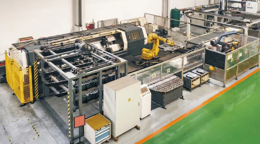
More than ten years of focused production experience in mechanical power transmission underlies every unit we manufacture. Over that time, we have built deep process knowledge across worm gear reducers, planetary drives, agricultural gearboxes, PTO shafts, hydraulic cylinders, motors, chains, and a broad catalogue of precision gears, sprockets, pulleys, and shafts—both standard catalogue items and non-standard parts engineered to customer drawings. That breadth means we function as a system supplier rather than a single-product vendor, giving procurement teams a single-source option for complete drivetrain assemblies.
Our manufacturing facility holds ISO 9001:2015 certification across the full production cycle, from raw material receipt through casting, forge, CNC machining, heat treatment, grinding, assembly, and final dimensional inspection. Housing castings are produced internally in grey iron, ductile iron, cast steel, precision investment-cast steel, and cast aluminium depending on application requirements. Finished gears and worm wheels are cut and ground on dedicated CNC hobbing and generating grinding machines, with first-article inspection reports available for OEM double speed worm gear reducer supplier programmes.
工作坊



Compatible Products & System Integration
The WPEKS input flange accepts standard IEC B3/B5/B14 motor frames across the full size range. Pairing the double speed reducer directly with our range of electric motors removes the need for adaptors and eliminates one potential misalignment point between motor and gearbox. Our technical team can confirm the correct motor power, frame, and shaft diameter for your worm reducer motor assembly before the order is placed, reducing commissioning risk for buyers building new machines or updating existing drives.

Complete 蝸輪箱 系列
Where the WPEKS hollow-bore design does not suit a particular installation geometry, our full worm gearbox range offers solid-shaft WPEDS, flange-mount WPEX, and compact NMRV series alternatives—all produced under the same quality system. Buying the complete drivetrain from one source simplifies warranty, spares planning, and technical support, particularly for machine builders managing multiple installation sites across different countries. This one-stop supply approach is an advantage whether you are specifying a standard nmrv worm reducer or a heavy-duty worm drive gearbox for process plant.

常見問題解答
Q1. What is the purpose of the EP-WPEKS double speed reducer when it is used in a hollow-shaft screw conveyor drive in an Australian grain handling facility?
The purpose of a double speed reducer in this context is to convert the motor's high rotational speed—typically 1,440 or 960 RPM depending on pole count and supply frequency—into the 5–30 RPM range that most screw conveyors require for controlled grain flow. The hollow-bore configuration of the WPEKS Double Speed Reducer is specifically advantageous here because the conveyor tube shaft passes directly through the reducer, creating a coaxial, coupling-free drive that reduces overhung load on the tube-end support bearing and simplifies the overall structure of the conveyor drive head.
Q2. Which shaft direction configuration of the WPEKS double worm gearbox is best suited for a vertical mixer drive in a food processing plant in the Netherlands or the UK?
Configuration B is generally the correct choice for vertical mixer drives because it positions the worm input shaft horizontally and the hollow output bore in the vertical axis, allowing the mixer paddle shaft to drop straight down through the reducer into the tank without angular offsets. It is also important to specify the correct oil fill volume for vertical mounting, as the standard fill level for horizontal mounting would leave part of the mesh unlubricated in a vertical orientation. Confirm the oil fill specification from the installation manual or with the engineering team before commissioning.
Q3. Is the EP-WPEKS worm gear reducer the same as a standard gearbox, and how does that affect my machine design for industrial automation in South Korea?
A worm gear reducer is technically a type of gearbox—both perform speed reduction through meshing gear elements—but the term gearbox in industrial automation often implies helical or bevel-helical variants. The WPEKS uses sliding worm-and-wheel contact rather than rolling involute tooth contact, which means lower efficiency at moderate loads but far higher reduction ratios in a single stage, inherent self-locking capability, quieter operation, and a more compact right-angle package. For South Korean automation applications where positioning accuracy and quiet running matter more than peak efficiency, the worm gear reduction ratio advantage often outweighs the efficiency trade-off.
Q4. Where should the oil level be set on an EP-WPEKS double worm gearbox when it is installed vertically for a stage-lift mechanism in the UK entertainment industry?
Oil fill level for vertical mounting differs from the horizontal position marked on the sight glass, and using the horizontal reference in a vertical installation is a common commissioning error that leads to premature bearing wear. The installation manual for the WPEKS Double Speed Reducer specifies separate fill volumes and sight-glass positions for each mounting attitude. As a general principle, vertical mounting with the worm above the wheel requires less oil than horizontal mounting because splash lubrication is more effective in that orientation; worm-below-wheel vertical mounting typically requires a slightly higher fill to ensure the worm mesh remains submerged during low-speed operation. Always consult the dimensional installation drawing and confirm with the technical team for the specific unit size before filling.
編輯:PXY