
Mining & Quarrying · Application Guide
A technical guide for process engineers, equipment designers, and maintenance teams specifying worm gear single speed reducers for spiral classifier drives in sand and aggregate washing plants across Australia, South Africa, Canada, the United States, Brazil, and Europe.
A spiral classifier — also called a screw classifier — is the workhorse of the sand washing and aggregate grading process. Its rotating helical screw lifts wet sand and gravel up an inclined trough, separating fine particles that overflow at the lower end from the coarser dewatered product discharged at the upper end. The drive that turns the spiral is typically a single speed reducer coupled to a standard AC induction motor, and its selection has a disproportionate effect on plant availability. A correctly specified worm gear reducer on a spiral classifier runs for years without significant intervention; an undersized or wrongly configured unit fails predictably within months of commissioning — often taking the classifier out of service at the peak of seasonal production demand.
What makes spiral classifier drives particularly demanding is the combination of a heavy, wet, abrasive load (saturated sand and gravel at 30–60% solids by weight), a high reduction ratio requirement (motor at 960–1450 RPM, spiral at 2–15 RPM), and continuous duty — the classifier typically runs for the full production shift, 10–20 hours per day, without regular stops. This article covers the selection criteria, manufacturing structure, material choices, lubrication requirements, and installation considerations that determine whether the single stage speed reducer chosen for a spiral classifier drive performs reliably across its full service life.
Drive Demand Profile of a Spiral Classifier
The torque profile of a spiral classifier drive differs from a belt conveyor or pump drive in two important respects. The first is the very high reduction ratio: the spiral typically operates at 2–15 RPM, which for a direct motor drive at 960 RPM requires a reduction of 64:1 to 480:1. This cannot be achieved in a single-stage helical or spur gear reducer without impractical gear sizes. A single speed worm gear reducer achieves ratios of 10:1 to 80:1 in a single stage, and the WP-series reducers cover up to 60:1 — meaning a two-stage arrangement (two reducers in series, or a motor-gearmotor combination with an integrated second stage) handles the full ratio range of large classifier installations while maintaining a compact, maintainable drive train.
The second distinguishing characteristic is the starting torque demand. A spiral classifier starting with a full load of wet sand in the trough — the normal condition after a production shift stop — requires a starting torque substantially higher than the running torque. The wet material in the trough compacts under gravity during the stop period, and the spiral must break out this compacted mass before it can move freely. Starting torque requirements of 2.0–3.5 times the running torque are not unusual, and the single speed reducer selected must carry this starting torque without yielding the gear teeth, overloading the bearings, or imposing damaging inrush loads on the motor. Correct service factor application at the selection stage is the primary protection against this failure mode.

Manufacturing Structure for Wet-Environment Spiral Classifier Service
أ single speed worm reducer for spiral classifier service must be manufactured to a standard that acknowledges the wet, abrasive operating environment. The key structural elements and the specific manufacturing requirements for classifier service are as follows. The worm shaft is machined from an integral alloy steel forging — the worm thread, shaft journals, and bearing seats are turned and ground in a single datum setup to ensure their concentricity is within 0.02 mm. This concentricity tolerance is tighter than the standard catalogue requirement because a spiral classifier shaft runs continuously for extended periods; any concentricity error manifests as a cyclic radial load on the output bearing that accelerates its fatigue life consumption at a rate proportional to the eccentricity squared.
The housing is a ribbed ductile iron casting with extended-reach shaft seal housings on both input and output sides. The extended seal housing accommodates a dual-lip seal arrangement rather than a single lip seal — the outer lip excludes water and fine sand particles from the seal cavity, while the inner lip retains the reducer lubricant. Between the two lips, a grease nipple allows the inter-lip cavity to be packed with waterproof grease, providing a third barrier against ingress and a first barrier against dry running of the inner lip in the event that the outer lip is breached. This triple-barrier sealing arrangement is standard practice for spiral classifier drives at sand washing plants in Australia, South Africa, and Brazil, where the combination of pump-sprayed wash water and fine silica abrasive creates the most demanding seal environment in the wet processing industry.
Material System for Spiral Classifier Duty
Chrome-manganese-titanium alloy steel, carburised to case depth 1.0–1.5 mm and hardened to HRC 58–62 on the thread flanks, then precision-ground. The spiral classifier drive does not impose the reverse-impact loads of a drill rig or the extreme starting shocks of an open-pit bucket, but it does require the worm to resist sustained bending load over continuous duty shifts — the alloy case depth and core toughness are dimensioned for fatigue life rather than impact resistance.
Tin-lead phosphor bronze tooth ring, centrifugally cast for microstructural uniformity, then finish-hobbed as a composite assembly with the ductile iron hub. The 10% tin content provides adequate compressive strength for the sustained contact pressures of a continuous-duty classifier drive, while the lead addition gives emergency dry-running tolerance — a practical benefit given that spiral classifier drives are occasionally re-started without verifying oil level after an extended holiday shutdown.
Ductile iron castings provide fracture toughness for the starting torque spikes of a loaded classifier restart while maintaining adequate stiffness to preserve worm-wheel alignment under the sustained radial load of continuous duty. External surfaces receive a high-build epoxy coating rather than standard paint, providing corrosion resistance in the acidic or alkaline wash water environments of Australian mineral sands, South African chrome slimes, and Brazilian silica sand washing operations.
Spiral classifier output shafts commonly impose both radial and axial loads on the reducer output bearing — the weight of the partially submerged spiral and its content has an axial component when the classifier is inclined, and the spiral’s pitch generates an axial force on the material it conveys that reacts into the drive. Tapered roller bearings in a cup-and-cone arrangement carry both load components, and the conical geometry prevents axial displacement of the shaft under the sustained one-directional thrust that characterises classifier service.
Inner lip: PTFE-faced radial shaft seal, rated to 100 °C continuous. Outer lip: NBR rubber excluding water and abrasive particles. Inter-lip cavity: packed with NLGI 2 calcium complex waterproof grease, re-greaseable via external nipple at 500-hour service intervals. This arrangement maintains seal integrity in direct wash water spray and silica slurry mist environments without requiring a special housing design or active pressurisation of the seal cavity.
The oil sump capacity for a spiral classifier worm gear reducer is sized to provide adequate thermal mass for continuous duty at the rated output torque. The EP-WPZ and EP-WPKZ series, with oil capacities from 0.4 to 5.2 litres, cover the range of sump sizes appropriate for spiral classifier drives from small portable washing plants to large fixed-installation sand washing facilities processing 200 t/h or more.
Selection Reference — Single Speed Reducers for Spiral Classifier Applications
The table below provides reference data for worm gear speed reducer selection across the range of spiral classifier sizes commonly installed in sand and aggregate washing plants. Reduction ratios in the 20:1 to 60:1 range cover the majority of classifier spiral speeds when used with a 4-pole (1450 RPM) or 6-pole (960 RPM) motor. For spiral speeds below 3 RPM on large classifiers, a two-stage arrangement (motor → first reducer → second reducer → classifier shaft) or a gearmotor with an integral planetary first stage is required to achieve ratios above 60:1 within standard catalogue frame sizes. Browse the full range at single speed reducer products.
| Classifier Size | Spiral Speed (RPM) | Typical Motor (kW) | Reduction Ratio | Recommended Series |
|---|---|---|---|---|
| Small portable washer | 8 – 15 | 0.75 – 2.2 | 10:1 – 20:1 | EP-WPDS (0.12 – 15 kW) |
| Small-medium fixed plant | 4 – 10 | 2.2 – 5.5 | 20:1 – 40:1 | EP-WPDS / EP-WPKA (5–260 kg) |
| Medium fixed plant | 2 – 6 | 5.5 – 11 | 30:1 – 60:1 | EP-WPKA / EP-WPKS (4–365 kg) |
| Large fixed plant (>150 t/h) | 2 – 4 | 11 – 22 | Two-stage arrangement | EP-WPKS + EP-WPKA in series |
| High-capacity mineral sands | 2 – 5 | 15 – 30 | Two-stage or planetary first stage | EP-WPDKA (5–350 kg) + EP-WPKS |
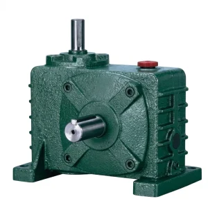
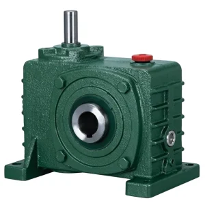
Recommended Products for Spiral Classifier Drive Applications

Lubrication for Continuous-Duty Wet-Environment Service
The lubricant in a spiral classifier single speed reducer must perform three simultaneous functions: provide an adequate oil film between the worm flank and the bronze wheel tooth under continuous load, resist emulsification when contaminated by the small quantities of water vapour or wash water that penetrate even a well-maintained seal system, and maintain adequate viscosity across the temperature range from cold morning start-up (5–10 °C in highland South African or Canadian operations) to the elevated steady-state temperature after several hours of continuous operation in a summer ambient of 35–40 °C.
The appropriate specification for most spiral classifier installations is an ISO VG 460 gear oil with extreme-pressure (EP) additives, confirmed tin-bronze compatibility (ASTM D130 copper corrosion test, 120 °C, 3 hours, Level 1 or 2), and an FZG test rating of minimum 10 to confirm the EP additive system is active at the contact stresses generated in a worm mesh. For installations in regions with high seasonal temperature variation — Canadian or Scandinavian operations — a synthetic PAO ISO VG 460 oil maintains more consistent viscosity across the temperature range and may extend the oil change interval from the 2000-hour standard to 3000 hours, reducing maintenance labour on the oil service task without compromising gear protection. Water contamination remains the dominant oil life-shortening factor in spiral classifier drives: quarterly oil sampling with water content measurement (Karl Fischer test, target below 0.2%) allows the oil change to be triggered by actual condition rather than elapsed hours alone.
Service Factor Application — The Loaded-Restart Problem
The single most common cause of spiral classifier reducer failure is selection without adequate service factor for the loaded-restart condition. A standard catalogue single speed reducer is rated for a smooth, uniform starting load — but a spiral classifier restarting with saturated sand compacted in the trough can require 2.5–3.5 times the running torque for the first 5–20 seconds of operation, until the spiral clears its initial resistance and enters steady rotation. If the selected reducer’s rated torque is only marginally above the running torque, the starting torque spike overloads the worm wheel tooth faces on every restart event, initiating contact fatigue that progresses to tooth spalling within a few hundred operating hours.
The recommended service factor for a spiral classifier drive is 1.5–2.0 times the running torque rating, applied before entering the reducer selection table. For classifiers in applications where the restart frequency is high — for instance a portable plant that stops and starts several times per shift — the factor should be at the upper end of this range. For classifiers in fixed-plant installations that restart from cold once per production shift, the lower end is acceptable if the start sequence includes a brief manual rotation of the spiral to break the compacted bed before motor start — a practice recommended in most proprietary classifier commissioning manuals for South African mineral processing and Australian quarry operations. Both the EP-WPZ and EP-WPKZ series are available in the frame sizes and reduction ratios needed to accommodate these service factors without requiring non-standard equipment.

Installation, Alignment, and Wet-Environment Protection
Spiral classifiers are inclined machines — the trough angle typically ranges from 14° to 20° from horizontal, and the drive sits at the upper (discharge) end of the classifier. This installation geometry means the reducer is mounted at an angle to the horizontal, which affects oil distribution within the housing. Most WP-series reducers are designed for horizontal mounting with the worm horizontal and the wheel vertical; when tilted to match the classifier inclination, the oil level shifts relative to the designed fill mark, potentially leaving the upper worm bearing partially unsubmerged. Confirming the oil fill and vent positions for the specific installation angle with the supplier before commissioning — and adjusting the oil level accordingly — is a mandatory step that is frequently omitted in the field, leading to premature upper bearing failure within the first 1000 hours of operation.
The drive housing should be positioned to allow wash water drainage away from the output shaft seal rather than toward it. A simple stainless steel drip shield above the output seal housing diverts the wash water spray that runs off the classifier trough structure from direct contact with the seal — a five-minute installation step that can double the seal service life in a high-spray environment. All external fasteners and the grease nipple on the inter-lip seal cavity should be stainless steel or hot-dip galvanised to resist the corrosive combination of silica fines, aluminium sulphate flocculant (used in many aggregate washing processes), and wash water that covers the drive station surface continuously during production.
Manufacturing Capability
Our manufacturing facility has worked in mechanical power transmission for more than a decade, building a product range that spans agricultural gearboxes, worm gear reducers, planetary gear drives, power take-off shafts, hydraulic cylinders, precision gears, roller chains, and electric motors — all governed by ISO 9001:2015 quality management system certification. Housing and structural components are produced in ductile iron, grey cast iron, cast steel, precision investment-cast steel, and aluminium alloy to suit the load and environmental profile of each application. Gear teeth, worm shafts, sprockets, pulleys, and output shafts are machined to DIN and ISO dimensional standards on multi-axis CNC hobbing, grinding, and turning centres. Customers requiring a complete spiral classifier drive system — reducer, motor, adapter flanges, and mounting hardware — can source all elements through a single manufacturing partner, eliminating the interface risk and lead-time management that comes with multi-vendor procurement for plant commissioning projects in Australia, South Africa, Canada, Brazil, and Europe.
ورشة عمل



Compatible Drive Components
A complete spiral classifier drive requires a matched motor and, for the highest-ratio applications, a compatible secondary reduction stage. The following products are available from the same manufacturing source, enabling procurement teams to specify a fully documented drive system.


الأسئلة الشائعة
المحرر: PXY