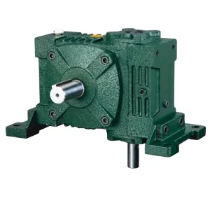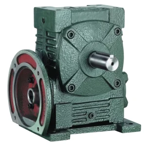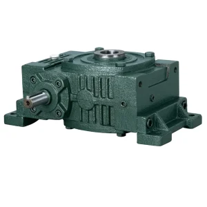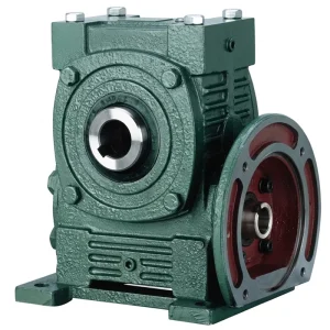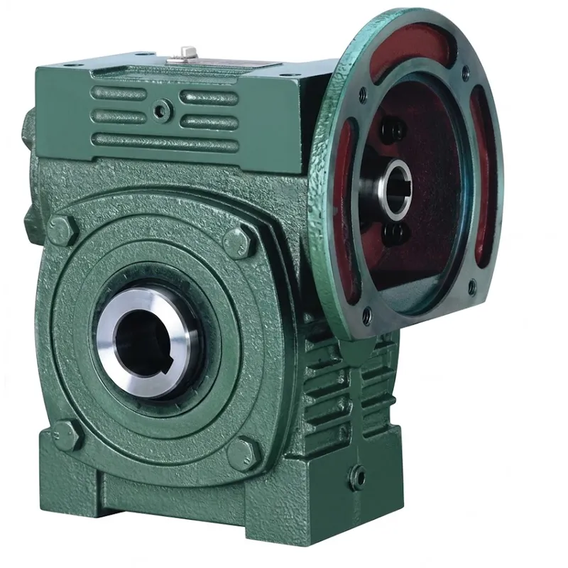
EP-0.12–15 kW WPWDK Universal Speed Reducer
The EP-WPWDK series is a compact worm gear reducer designed for direct motor integration, featuring a robust cast iron housing and integrated motor flange. Available in sizes 40 to 250, it supports power inputs from 0.12 kW to 15.0 kW with reduction ratios ranging from 1/5 to 1/60. Weighing between 4 kg and 376 kg, the unit offers versatile shaft direction configurations (A and B) for flexible installation. Key specifications include motor flange compatibility up to M24 and output shafts up to 28×116.4 mm. This universal speed reducer ensures efficient torque transmission and space-saving design, making it ideal for industrial machinery requiring reliable speed control and direct-drive capabilities in constrained environments.
Universal Speed Worm Reducer Series
EP-WPWDK Universal Speed Reducer
0.12–15 kW | IEC Flange-Mount Hollow Output Shaft
The EP-WPWDK is a flange-input, hollow-output universal speed reducer that combines the compact geometry of the WP worm gear family with an IEC-standard motor mounting face. Available across sizes 40 through 250 — covering input power from 0.12 kW to 15 kW — this worm gear speed reducer delivers right-angle torque conversion with direct motor attachment and a hollow bore output shaft, making it one of the most integration-friendly configurations in the WPWD range for machine builders and OEM applications worldwide.
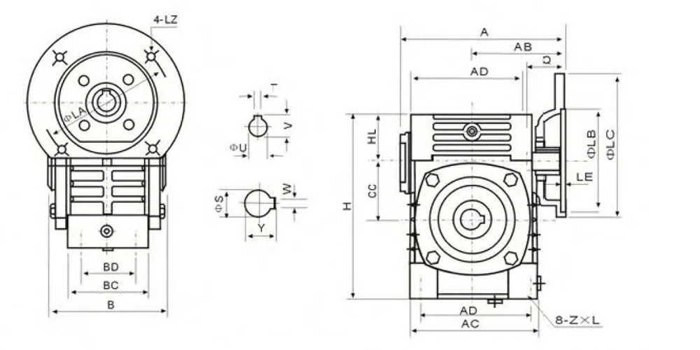
Technical Specifications — EP-WPWDK Series Universal Speed Reducer
All dimensions in mm. Motor flange bolt pattern follows IEC standards. Output shaft W×Y = bore diameter × bore depth.
| 크기 | Input (kW) | 비율 | 에이 | AB | 비 | AC | BC | AD | CC | HL | 시간 | Z×L | Motor Flange | Input T×V | Output W×Y | 무게(kg) |
|---|---|---|---|---|---|---|---|---|---|---|---|---|---|---|---|---|
| 40 | 0.12 | 1/5 | 135 | 75 | 85 | 95 | 61 | 78 | 42 | 40 | 35 | 125 | M6×12 | 4×12.8 | 6×18.8 | 4 |
| 50 | 0.18 | 1/5 | 151 | 83 | 105 | 111 | 68 | 85 | 50 | 50 | 35 | 150 | M6×18 | 4×12.8 | 6×22.8 | 7 |
| 60 | 0.37 | 1/5 | 167 | 91 | 110 | 127 | 76 | 105 | 55 | 60 | 42 | 177 | M8×20 | 5×16.3 | 8×28.3 | 10 |
| 70 | 0.37 / 0.75 | 1/5–1/10 | 200–202 | 109–111 | 130 | 152 | 86 | 125 | 65 | 70 | 55 | 215 | M10×25 | 5×16.3 / 6×21.8 | 8×33.3 | 14.5 |
| 80 | 0.75 / 1.5 | 1/15 | 225 | 125 | 150 | 169 | 102 | 140 | 70 | 80 | 65 | 250 | M12×28 | 6×21.8 / 8×27.3 | 10×38.3 | 23 |
| 100 | 1.5 | 1/20 | 280 | 148 | 160 | 216 | 117 | 180 | 90 | 100 | 80 | 310 | M12×30 | 8×27.3 | 12×43.3 | 36.5 |
| 120 | 2.2 / 3.0 | 1/25–1/30 | 333 | 181 | 175 | 256 | 124 | 220 | 100 | 120 | 95 | 370 | M14×32 | 8×31.3 | 14×48.8 | 54 |
| 135 | 3.0 / 4.0 | 1/40 | 375 | 202 | 210 | 296 | 147 | 260 | 110 | 135 | 105 | 425 | M16×35 | 8×31.3 | 18×64.4 | 83 |
| 155 | 5.5 | 1/50 | 448 | 247 | 256 | 345 | 185 | 280 | 120 | 155 | 103 | 461 | M16×35 | 10×41.3 | 20×74.9 | 110 |
| 175 | 5.5 / 7.5 | 1/60 | 481 | 262 | 282 | 374 | 192 | 320 | 140 | 175 | 123 | 521 | M16×35 | 10×41.3 | 22×85.4 | 156 |
| 200 | 11.0 | 1/60 | 543 | 285 | 320 | 412 | 230 | 360 | 150 | 200 | 130 | 575 | M20×36 | 12×45.3 | 22×90.4 | 222 |
| 250 | 11.0 / 15.0 | 1/60 | 615 | 330 | 400 | 500 | 285 | 420 | 190 | 250 | 150 | 700 | M24×42 | 12×45.3 | 28×116.4 | 376 |
* BD and full sub-dimension drawings available on request per size. Contact our technical team for complete dimensional documentation.
Five Key Advantages of the EP-WPWDK Universal Speed Reducer
Why machine builders and OEM engineers specify this universal speed reducer in new designs
IEC Flange + Hollow Bore in One Unit
The WPWDK Universal Speed Reducer configuration uniquely combines an IEC-standard motor mounting flange on the input face with a hollow output bore on the driven side. This means the motor bolts directly onto the reducer — no coupling, no motor bracket — while the driven machine shaft inserts through the hollow output hub. Two typical integration steps collapse into a single bolted assembly, which is a meaningful time saving in production line installation and field replacement scenarios for a new universal speed worm reducer.
Dual Shaft Direction — A and B
The EP-WPWDK Universal Speed Reducer is offered in two shaft direction configurations: A (hollow double output, top input) and B (hollow double output, side input). This covers the two most common machine layout orientations without custom fabrication. Engineers specifying a universal speed worm gear reducer for vertical or horizontal machine drive arrangements can select the appropriate configuration directly from the standard catalogue and install without modifying the driven machine structure or the motor mounting arrangement.
Wide Ratio Coverage — 1/5 Through 1/60
The available worm gear reduction ratio range from 1/5 to 1/60 makes this series genuinely versatile across industries. A 1/5 ratio gives relatively fast output for blending and agitation; a 1/60 ratio produces the deep speed reduction and high multiplication of torque required for slow-speed heavy loads such as gate valve actuators, clarifier drives, and large-format conveyor head pulleys. The same housing design and mounting pattern serve all ratios within a given size, simplifying spares management for facilities that operate multiple machines with different speed requirements.
Self-Locking at High Ratios
At reduction ratios of 1/30 and above, the EP-WPWDK universal speed reducer exhibits inherent back-drive resistance — the load cannot rotate the worm backward through the gear pair once the motor is stopped. This property is particularly useful in hoisting, gate, and positioning applications where the load must remain stationary without an active brake. It reduces system complexity and the number of components that need periodic maintenance, which is a real advantage for field installations in remote locations across Australia, Canada, and South Korea where servicing frequency should be minimised.
Full Size Range — One Consistent Design Language
From the 4 kg size-40 unit through to the 376 kg size-250 unit, the EP-WPWDK maintains consistent dimensional relationships and installation standards. A maintenance technician trained on one size can service another size from the same series without re-learning oil fill procedures, bearing removal sequences, or seal replacement protocols. For procurement teams in the UK, Netherlands, Brazil, and Colombia, this means a single technical datasheet and one supplier qualification covers the complete drive train requirement across a multi-machine facility — a meaningful reduction in procurement and documentation overhead.
What Is the EP-WPWDK Universal Speed Reducer?
The WPWDK universal speed reducer designation identifies a specific configuration within the WP family of industrial universal speed reducer units. The "DK" suffix indicates dual-hollow-output with IEC motor flange input — distinguishing it from the WPWD (solid output shaft, multi-direction) and WPWKO universal speed reducer (hollow output, foot-mounted) variants. Like all WP-type worm gear reducer gearbox units, it transmits power between non-parallel, non-intersecting shafts at 90 degrees using a hardened steel worm thread meshing with a phosphor bronze worm wheel.
What makes the WPWDK universal speed reducer particularly well suited to OEM machine building is the integration of the IEC motor flange. Rather than requiring a separate motor bracket or bell housing adapter, the motor bolts directly onto the input face of the reducer housing using the standard IEC frame bolt pattern — M6×12 at size 40 through M24×42 at size 250. This flange-mount arrangement eliminates the motor-to-reducer coupling assembly entirely, reducing the total drive train component count and allowing closer motor positioning relative to the driven machine axis.
The hollow output shaft accepts the driven machine shaft directly through the output hub. This is especially valuable in applications where the machine shaft is long, protrudes from both sides of the reducer, or must be inserted from the side of the machine rather than end-on. The EP-WPWDK is available as a worm reducer for sale across a full size range from 40 to 250, with unit weights spanning 4 kg to 376 kg and input power ratings from 0.12 kW to 15 kW.
How the WPWDK Worm Gear Drive Works
The operating principle of the EP-WPWDK is identical to that of all worm speed reducer gear box designs: a multi-start or single-start helical worm thread on the input shaft engages the teeth of a worm wheel on the output shaft at a 90-degree crossing angle. Each complete rotation of the worm advances the worm wheel by the number of worm thread starts — one tooth increment per start per revolution. For a single-start worm with 40 teeth on the wheel, the output shaft completes one revolution for every 40 motor revolutions, producing a worm gear reduction ratio of 1/40 and a torque multiplication of approximately 40 × efficiency at the output bore.
The IEC flange input of the WPWDK universal speed reducer transmits motor torque directly to the worm shaft through a keyed or shrink-disc connection at the motor shaft, without an intermediate shaft or coupling. The motor rotor mass is supported partially by the reducer input bearings, so it is important during worm gear reducer installation to verify that the motor weight and overhung load are within the rated input shaft bearing capacity for the selected size. For sizes 40 through 100, a motor support bracket is recommended for motors above IEC 90 frame to reduce cantilevered bending at the input shaft bearing.
Materials & Construction Standards of Universal Speed Reducer
The housing of the EP-WPWDK is machined from GG25 grey cast iron casting, which provides excellent vibration-damping characteristics alongside the structural rigidity needed to maintain bearing alignment under the combined axial and radial loads of a heavy duty worm drive gearbox installation. The IEC motor flange face is precision-machined to H7 tolerance to ensure concentric motor shaft alignment without shimming or adjustment during installation. For applications at size 200 and above where reaction torques are substantial, ductile iron housing material is available as an upgraded specification.
The worm shaft is produced from 20CrMnTi case-hardening alloy or 42CrMo medium-carbon steel, through-hardened and then precision-ground after heat treatment to achieve thread flank hardness of HRC 45–55. The worm wheel is centrifugally cast from ZCuSn10Pb1 phosphor bronze — an established material choice for premium worm reducer applications, offering low friction against hardened steel, high thermal conductivity to dissipate contact heat, and good embedability for run-in debris. \
Application Scenarios of Universal Speed Reducer
Where the flange-mount hollow-bore design of this universal speed reducer delivers a practical edge
OEM Compact Machine Drives
Machine tool builders and packaging equipment manufacturers in South Korea and the Netherlands that design for minimum footprint specify the WPWDK universal speed reducer because it eliminates both the motor bracket and the coupling assembly from the motor-to-drive connection. The motor bolts directly onto the IEC flange face, and the drive shaft passes through the hollow output bore — reducing the drive train to its minimum physical length. This is a meaningful benefit when machine width or depth is constrained by transportation or installation space limits.
Vertical Agitator Shafts
Fermenter agitators, chemical reactor stirrers, and paint blending tanks in UK and Brazilian process plants commonly mount the motor-reducer unit directly on top of the vessel lid with the agitator shaft descending through the hollow output bore of the reducer. The flange-mount input of the WPWDK universal speed reducer is ideal for this arrangement — the motor and reducer form a single vertical column assembly that requires only one base mounting point on the vessel cover, simplifying both the initial installation and eventual shaft withdrawal for inspection or seal replacement.
Agricultural Feed Conveyors
Poultry and dairy farm feed delivery systems in Australia and Canada use the worm drive speed reducer in the 60–100 size range to drive feed auger conveyors at controlled output speeds of 20–60 rpm. The flange-mount input accepts standard IEC 63 through IEC 100 motors used widely across agricultural machinery, and the hollow bore mounts directly onto the auger pipe. Clean maintenance access and sealed lubrication extend the service interval to match the once-per-season maintenance schedule typical of intensive livestock operations.
Indexing Turntables & Rotary Tables
Assembly line rotary indexing tables and pallet changers in Korean and Colombian automotive supplier plants use the EP-WPWDK universal speed reducer as the primary drive unit. The hollow bore accepts the table's central column shaft, and the inherent low backlash of the worm gear pair ensures accurate angular positioning at each index step without a secondary positioning mechanism. At ratios of 1/40 and above, the self-locking characteristic retains the table position securely between index cycles when the motor is decelerated to rest by the drive inverter.
Irrigation & Water Gate Drives
Canal gate operators and irrigation sluice drives in rural Australia and South America require a worm gear reducer motor pairing that can hold its output position indefinitely without electrical power, resist moisture and dust ingress over multi-year installation periods, and operate reliably in outdoor temperature extremes. The EP-WPWDK at size 135 through 175 with 1/50 or 1/60 ratios delivers self-locking, sealed construction, and a broad enough size range to match gate spindle diameters from 18 mm to 85 mm through the hollow output bore.
Textile Winding & Finishing Machinery
Textile mills in the Netherlands and across Europe use the WPWDK in the 40–80 size range to drive fabric winding mandrels, yarn tension rolls, and stenter chain drives. The smooth torque output of the 웜 기어 감속기 at these smaller sizes avoids the fabric distortion that can occur with pulsating drive systems. The integrated motor flange keeps the drive unit compact enough to fit within the tight machine frame of a typical stenter or winder without structural modification to the textile equipment frame.
About us - Universal Speed Reducer Manufacturer
Over a decade of dedicated engineering practice in mechanical power transmission has shaped how we design and build every universal speed worm gear reducer that leaves our facility. Our production portfolio spans agricultural gearboxes, worm gear reducers, planetary gear drives, power take-off shafts, hydraulic cylinders, gears, chains, and motors — giving us the manufacturing depth to serve as a complete drive system supplier rather than a single-component source. This breadth also means our engineering team has first-hand operational knowledge of how each component type performs in context, which informs smarter design choices across the range.
The facility operates under ISO 9001:2015 quality management certification, with documented procedures governing raw material incoming inspection, in-process machining tolerances, gear tooth accuracy verification, assembly sequence, and final functional testing before despatch. Casting materials across our gearbox range include ductile iron, grey cast iron, cast steel, precision investment cast steel, and cast aluminium — each selected to the mechanical demands of the specific unit rather than defaulted to a single grade for convenience.
작업장




관련 상품
One-stop supply for complete worm drive systems — motors, reducers, and accessories from a single source

전기 모터
The WPWDK is designed around IEC motor flange dimensions, meaning our 전기 모터 range — covering IEC frame 56 through 200 in 4-pole and 6-pole configurations — bolts directly onto the reducer input face with no intermediate adapter required. Ordering the electrical motors universal speed worm reducer package from us allows our team to pre-check thermal compatibility, confirm motor weight against input shaft bearing load ratings, and ship the complete drive assembly as a single verified unit ready for installation.

Full Worm Gearbox Range
The WPWDK is one configuration within a comprehensive portfolio of 웜 기어박스 types we produce — including nmrv worm reducer aluminium units, WPWD solid-shaft series, WPWKO foot-mounted hollow bore, and custom double-reduction configurations. If your application calls for a worm reducer gearbox premium with specific shaft orientations or mounting arrangements not covered by a standard type.
자주 묻는 질문
What makes an IEC flange-mount universal speed reducer a better choice than a foot-mounted worm gearbox for a compact OEM machine drive in South Korea?
For OEM machine designs where installation space is tight, the IEC flange-mount universal speed reducer configuration of the WPWDK universal speed reducer eliminates the motor bracket, coupling, and coupling guard that a foot-mounted arrangement would require. The motor bolts directly onto the reducer flange, the reducer mounts onto the machine frame, and the driven shaft passes through the hollow bore — three separate mechanical interfaces collapse into two.
How do I find the correct replacement universal speed reducer when the existing WPWDK unit on a UK textile winder has lost its nameplate and I can only measure external dimensions?
The most reliable identification method is to measure the dimension A (overall length from input face to output bore end face) and the dimension AB (width across the housing). These two values, cross-referenced with the motor flange bolt circle diameter and the hollow output bore diameter, will uniquely identify the size within the WPWDK series. Once size is confirmed, the reduction ratio can be determined by counting input shaft rotations required to produce one complete output shaft revolution — count carefully at low speed with the motor disconnected and the machine shaft turning manually.
Which size universal speed reducer is the right fit for a vertical agitator drive in a Brazilian chemical plant that needs a 1/40 ratio and around 3 kW input from an IEC 100 motor?
For a 3 kW IEC 100 motor at 1/40 ratio in a vertical agitator application, the EP-WPWDK-135 universal speed reducer is the correct selection. Size 135 is rated at 3.0–4.0 kW input and covers the 1/40 ratio as a standard catalogue configuration. The IEC 100 motor frame dimension matches the M16×35 flange bolt pattern on size 135. For a vertical agitator shaft mounting, confirm that the output bore diameter W×Y (18×64.4 for size 135) accommodates your agitator shaft diameter and key dimensions.
편집자: PXY