
Food & Beverage Industry — Poultry Processing
A technical guide for plant engineers and equipment specifiers on selecting, installing, and maintaining worm gear single speed reducers across poultry evisceration, scalding, and chilling conveyor systems worldwide.
Drivetrain Reliability in Poultry Processing: Why the Reducer Matters
Poultry processing plants operate at production speeds measured in birds per hour — and every hour of unplanned downtime on an evisceration line or chilling conveyor has an immediate, quantifiable cost. The mechanical drivetrain that moves overhead conveyor chains, shackle lines, screw chillers, and offal handling systems through the plant relies heavily on a single speed reducer to convert motor speed into the controlled, sustained torque that each drive station requires. In high-volume facilities processing 10,000 to 30,000 birds per hour across markets in Brazil, the United States, Thailand, the Netherlands, and Australia, the reliability of a worm gear single speed reducer is not an abstract engineering specification — it is a direct input to production throughput and processing hygiene compliance.
The evisceration and chilling sections of a poultry plant impose operating conditions that set them apart from general industrial conveyor applications. Persistent water spray, high-pressure washdown with alkaline and acid detergent solutions, low ambient temperatures in chilling areas, and the continuous duty cycle that large-scale poultry operations demand all combine to stress gear reducer components in ways that standard equipment specifications may not capture. This guide addresses the construction and material choices that determine long-term reducer performance in these environments, and explains how to match a single speed reducer to the specific torque and speed requirements of each line position.

Manufacturing Structure of WP Series Single Speed Reducers
The WP series worm gear single speed reducer follows a right-angle, single-reduction architecture. The input worm shaft is supported by tapered roller or angular-contact bearings, and its hardened thread engages a bronze worm wheel mounted on the output shaft. Both shafts are enclosed in a precision-machined cast housing, with oil retained inside the sealed gear chamber and isolated from the exterior by lip seals on each shaft exit. The output shaft is available in solid single-side, solid double-side, or hollow configurations depending on the model variant, which allows the same mechanical design to serve a range of mounting and coupling requirements across different conveyor drive positions in a poultry facility.
For poultry processing duty, several structural details are particularly relevant. The housing is machined to close bore tolerances, which keeps bearing fits within specification throughout the thermal cycling that occurs when a plant shifts from production temperatures to cold water chilling temperatures and back. Shaft seal housings are machined as integral features of the main casting rather than pressed-in inserts, providing stable retention geometry even after years of CIP chemical exposure. The external housing surface has no upward-facing channels or recesses, which means wash water and organic process debris cannot pool on the reducer surface — a practical requirement in wet evisceration environments where bacterial accumulation on equipment surfaces is a food safety control point.
Housing
Precision-machined grey cast iron or cast aluminum. Sealed filler/drain ports, no upward recesses. External surfaces compatible with food-facility paint systems.
Worm Shaft
Case-hardened alloy steel, thread-ground. HRC 45–55 surface hardness. Tapered roller or angular-contact bearings handle combined radial and axial loads from conveyor chain pull.
Worm Wheel
Tin-bronze or phosphor-bronze alloy keyed to a steel hub. Produces low friction and smooth torque output — important for stable overhead conveyor chain speed control.
샤프트 씰
FKM (Viton) double-lip radial seals. Rated for alkaline CIP detergents and steam sterilization temperatures common in evisceration line washdowns.
Material System: Choices That Govern Poultry Plant Service Life
Material selection across each component of a worm speed reducer has direct consequences for service life in poultry processing environments. The housing material determines corrosion behavior, thermal stability, and the ability to hold a food-compatible surface coating. Grey cast iron remains the most widely specified housing material in poultry facility installations because it offers good rigidity under the sustained vibration loads of continuously moving overhead chains, machines to close tolerances, and can be finished with epoxy or polyurethane paint systems that resist the detergent chemistries used in poultry plant cleaning schedules.
Lubricant selection is the material decision with the most direct food safety relevance. Overhead conveyor drives and shackle line sprocket stations are positioned above open product flows throughout the evisceration section. Any gear reducer with a shaft seal failure in this position risks contaminating product below. Specifying H1-registered food-grade gear lubricants — either synthetic polyalkylene glycol (PAG) based or white mineral oil based, both available in the ISO VG 220–320 viscosity grades appropriate for worm gear applications — eliminates the product contamination consequence of a minor seal weep. Many poultry processing plants in the United States, European Union, and Australia now require H1 lubricant documentation as a standard element of their food safety management systems, regardless of whether each individual reducer is directly over an open product zone.
| Component | Standard Material | Poultry Plant Relevance |
|---|---|---|
| Housing | Grey cast iron, epoxy sealed | Resists detergent attack; stable under conveyor vibration loads |
| Worm shaft | Alloy steel, HRC 45–55 | Long wear life across 24-hr/day chilling line duty |
| Worm wheel | Tin-bronze CuSn alloy | Low mesh friction controls oil temperature at sustained low RPM |
| Shaft seals | FKM (Viton) double-lip | Survives alkaline/acid CIP cycles and steam sterilization |
| Lubricant | H1 synthetic PAG or white mineral oil, ISO VG 220–320 | Food safety compliance for above-product-zone installation positions |
| Bearings | Chrome steel tapered roller | Handles axial chain pull load from shackle conveyor tension |
Recommended Model: EP-WPKS Single Speed Reducer for Poultry Conveyor and Chiller Drives
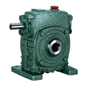
EP-WPKS — 4 to 365 kg Single Speed Reducer
The EP-WPKS covers a weight range from 4 kg to 365 kg across its size progression, spanning the full spectrum of conveyor drive station sizes encountered in modern poultry processing plants — from lightweight offal conveyor drives at the low end through to heavy-duty overhead shackle line sprocket drives and screw chiller tube drives at the upper range. The KS configuration combines a hollow output shaft with a flange face, allowing the reducer to be mounted directly onto the conveyor head shaft without an intermediate coupling — removing a maintenance access point and reducing the drivetrain length at each drive station.
The combination of hardened worm shaft and bronze worm wheel in the WPKS delivers the quiet, vibration-dampened operation that large poultry facilities value on shackle lines running at constant speed through continuous production shifts. Reduction ratios in the standard range cover the output speeds from 15 RPM to 150 RPM that overhead conveyor and screw chiller systems typically require when driven by standard 4-pole induction motors. The solid and hollow output shaft options make the WPKS adaptable to both new equipment builds and conveyor drive replacement projects where the head shaft diameter is already fixed.

Drive Positions and Torque Requirements Across a Poultry Processing Line
A complete poultry processing line from live reception through to packaged product involves multiple distinct conveyor and processing machine drive stations, each placing different demands on the single speed reducer installed at that position. The overhead shackle line that carries birds through scalding, plucking, and evisceration sections runs at a carefully controlled constant speed — typically 5,000 to 12,000 birds per hour depending on plant capacity — and the reducer drive must maintain that speed steadily throughout a production shift with minimal speed variation. Gear ratio selection for the shackle line drive is governed by the target chain speed in meters per minute, the sprocket pitch, and the motor synchronous speed.
Chilling section drives present a different load profile. Immersion chiller auger screws, which move partially chilled carcasses through water-filled stainless steel troughs, operate at low RPM — often 2–10 RPM at the auger — and require high sustained torque from the worm gear single speed reducer due to the combined resistance of the screw mechanism and the water column. Screw chiller drives in large North American and Brazilian processing plants are one of the most torque-demanding applications in the poultry drivetrain, requiring careful service factor application and thermal rating verification to avoid gear reducer overloading during sustained production runs.
| Drive Position | Typical Output RPM | Load Character | Service Factor | Recommended Variant |
|---|---|---|---|---|
| Overhead shackle line | 15–40 | Constant, moderate | SF 1.5 | WPKS / WPKA |
| Scalder conveyor | 20–60 | Constant, moderate | SF 1.5 | WPDS / WPKS |
| Plucker drum drive | 60–120 | Moderate impact load | SF 2.0 | WPDS / WPKA |
| Screw chiller auger | 2–10 | High sustained torque | SF 2.5 | WPDKA / WPKS (large) |
| Offal conveyor | 30–80 | Light, occasional jam | SF 1.5 | WPZ / WPKZ |
| Packaging infeed conveyor | 20–50 | Constant, light | SF 1.5 | WPDS / WPKS |
Washdown Resistance and Hygiene Design in Wet Evisceration Zones
The evisceration section of a poultry processing plant is a wet, warm, and chemically aggressive environment. High-pressure water jets are used continuously during production to flush organic waste from conveyor surfaces, and daily deep-cleaning schedules in facilities operating under USDA, EU food hygiene directive, or equivalent national regulatory frameworks involve prolonged contact between all equipment surfaces — including gear reducer housings — and alkaline caustic foam, acidic rinse solutions, and sometimes steam sterilization vapor. A single speed reducer specified for this environment needs to perform reliably despite that repeated chemical and thermal assault on its external surface, its shaft seals, and its oil fill.
Practical hygiene measures for poultry plant reducer installations include specifying FKM double-lip shaft seals rather than standard NBR elastomers, scheduling seal replacement at intervals tied to CIP cycle frequency rather than calendar time, applying a food-compatible epoxy topcoat to the cast iron housing surface prior to installation, and positioning reducers where feasible to avoid direct high-pressure jet impact on shaft seal areas. Facilities audited under SQF, BRCGS, or Global G.A.P. standards are increasingly expected to document the H1 lubricant status of all gear reducers positioned above or adjacent to open product streams — a requirement that should be confirmed with the reducer supplier before procurement and recorded in the HACCP documentation maintained for the installation zone.
Continuous Duty Cycle: Thermal Management in 24-Hour Poultry Operations
Large poultry processing plants frequently operate two or three shifts per day, with conveyor and chilling systems running continuously for 16 to 24 hours before a scheduled maintenance window. A single speed reducer installed on a screw chiller drive or a shackle line in this operating pattern accumulates far more running hours per calendar year than the same unit would in a typical industrial application, reaching 8,000–6,000 operating hours per year — a figure that compresses the service intervals for oil changes, seal inspections, and bearing assessments relative to standard industrial schedules.
Thermal power rating is the specification parameter that determines whether a given reducer can sustain its rated output without exceeding safe oil temperature limits during those long continuous runs. For worm gear single speed reducers, the thermal rating is typically expressed as continuous input power at a reference ambient temperature. In poultry processing facilities where the scalder and evisceration halls can reach 30–40°C ambient from process steam and the heat generated by large numbers of birds, the effective thermal headroom of the reducer is reduced from its catalogue value. Where the thermal rating is borderline for the application duty, specifying an external cooling fan on the input shaft can extend the continuous power capacity by 40–60%, avoiding the alternative of moving up to a larger and heavier reducer frame size.
Oil Change Interval
Break-in oil change at 200 hours; thereafter at 4,000–6,000 hours or as determined by oil analysis. In 24-hr poultry plants this equals 8–12 months.
Seal Inspection
FKM seals in wet evisceration zones: inspect every 6 months. Replace at first sign of weeping oil on output shaft — do not defer to the next planned shutdown.
Temperature Check
Housing surface above 80°C during production indicates oil degradation, seal failure, or overloading. Stop and investigate before resuming production.
Bearing Life
Plan bearing assessment at 15,000–20,000 hours. In a 24-hr/day facility this window arrives in approximately 2–3 years of operation.

Customized Single Speed Reducer Solutions for Poultry Equipment Manufacturers
Poultry processing equipment manufacturers designing evisceration lines, chilling systems, and overhead conveyor frameworks for customers in markets from the United States and Brazil to the Netherlands, Thailand, and Australia often require a customized single speed reducer that differs from standard catalogue configurations. Common OEM customization requests include hollow shaft bore diameters sized to match proprietary head shaft dimensions on existing conveyor systems, modified mounting flange patterns to align with established frame drilling layouts, and stainless steel shaft extensions for drive stations in high-pressure spray zones where standard carbon steel shafts would corrode unacceptably quickly. Paint system specifications compatible with aggressive cleaning chemistry — high-solids epoxy or polyurethane topcoats rather than standard industrial enamel — are another frequent OEM request for poultry plant installations.
Documentation requirements for poultry equipment OEMs have grown more demanding as food safety auditing schemes have proliferated. CE Declaration of Incorporation for machinery directive compliance, material test certificates for bronze wheel alloys confirming composition and mechanical properties, H1 lubricant product datasheets, and dimensional drawings in formats compatible with CAD system import are all elements that OEM engineering teams need to compile their machine technical files. Working with a single speed reducer manufacturer that maintains an ISO 9001:2015 certified quality management system means that documentation requests of this type can be fulfilled systematically without requiring custom data collection for each order.
Ready to Specify for Your Poultry Line?
Explore the Full Range of Single Speed Reducers
The complete WP series spans input power from 0.12 kW to 15 kW across hollow and solid shaft configurations, with reduction ratios and torque ratings matched to every drive position in a modern poultry processing facility.
Related Products: Complete Drivetrain for Poultry Processing Lines
A worm gear single speed reducer works most effectively as part of an integrated drivetrain where motor, reducer, and mechanical drive components are matched to the same application duty and sourced with compatible documentation. Sourcing matched components from a single supplier reduces procurement lead time, simplifies spare parts management across multiple drive stations, and provides a single point of contact for technical support across the full drivetrain package.


회사 소개
The manufacturing range covers agricultural gearboxes, worm gear reducers, planetary gear drives, power take-off shafts, hydraulic cylinders, gears, chains, and motors. All production operates under an ISO 9001:2015 certified quality management system. Engineering and manufacturing capabilities extend to industrial and agricultural gearboxes and assemblies produced in ductile iron, cast iron, cast steel, precision cast steel, and cast aluminum, together with gears, sprockets, worm gears, pulleys, worms, shafts, and a broad portfolio of standard and non-standard mechanical parts. This depth of in-house manufacturing capability supports poultry equipment OEMs, processing plant operators, and after-market distributors in markets across North America, Europe, South America, Asia-Pacific, and the Middle East.
작업장



자주 묻는 질문
What single speed reducer torque rating and service factor should I specify for a screw chiller auger drive in a large North American poultry processing plant running 20 hours per day?
For screw chiller auger drives, the load profile involves high sustained torque at very low output RPM — typically 2–10 RPM — combined with the resistance of a full water column in the chiller trough. Apply a service factor of SF 2.5 against the calculated running torque to arrive at the minimum reducer output torque rating. Verify the thermal power rating at your plant ambient temperature, which in evisceration halls can reach 35–40°C. Specify an H1-registered synthetic gear oil and FKM shaft seals as baseline requirements for any installation above or adjacent to product-carrying water channels in the chilling section.
How do I find a reliable worm gear single speed reducer supplier for poultry conveyor drives in Brazil or Southeast Asia who can supply H1 food-grade certified lubricant documentation?
Request confirmation of ISO 9001:2015 certification before placing an order, and ask for the H1 lubricant product datasheet to be included with shipment documentation for each unit. For Brazilian market installations operating under MAPA food safety oversight, and for Southeast Asian facilities certified under SQF or BRCGS, documented H1 compliance is a standard audit requirement. A single speed reducer manufacturer with established export experience can typically provide dimensional drawings, material certificates, and H1 lubricant confirmation within standard lead times for international orders.
What are the disadvantages of using a single reduction worm gear reducer on a high-capacity poultry overhead shackle line running continuously for 24 hours in a European processing facility?
The primary disadvantage of a single reduction worm gear reducer in this application is lower mechanical efficiency compared to helical alternatives — typically 65–85% depending on ratio and sliding velocity — which means more motor input power converts to heat in the gear mesh rather than useful chain pull. In a 24-hour operation with many drive stations, the cumulative energy cost across a full shackle line fleet is a meaningful consideration. Heat management is the practical consequence: the thermal power rating of the chosen reducer must be confirmed against the actual duty at elevated plant ambient temperatures, and cooling fan upgrades may be needed on units approaching their thermal limit. These factors must be weighed against the simpler mechanical architecture, lower capital cost, and quieter operation that make the single speed worm drive the preferred choice for most poultry conveyor installations of moderate power.
When should a poultry equipment OEM in the Netherlands or Australia consider ordering a customized single speed reducer rather than selecting a standard catalogue unit for their evisceration line build?
Customized single speed reducer variants make sense when the conveyor head shaft diameter does not match standard hollow bore dimensions, when the frame structure requires a non-standard flange bolt circle, when the installation zone demands stainless steel shaft extensions for aggressive washdown conditions, or when a specific gear ratio outside the standard range is needed to match a target chain speed precisely. For OEM equipment builders in the Netherlands and Australia supplying to facilities under EU hygiene regulations or Australian FSANZ standards, requesting customized variants with CE declaration and full material certification documentation allows the reducer to be incorporated directly into the machine technical file without additional supplier data requests.
편집자: PXY