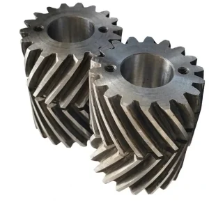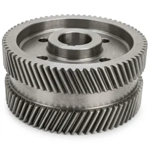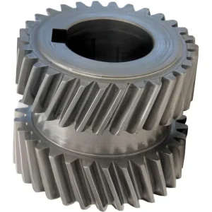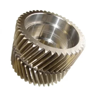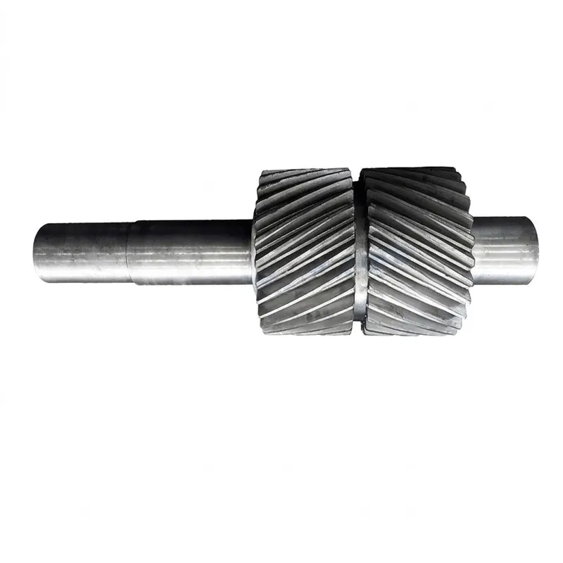
EP-Rolling Mill Double Helical Gear
그만큼 EP-Rolling Mill Double Helical Gear is a heavy-duty transmission component engineered for extreme industrial environments, including marine and agricultural machinery. Manufactured from high-strength 42CrMo alloy steel (equivalent to AISI 4140/SCM440), it undergoes high-frequency quenching to achieve a tooth surface hardness of 50–55 HRC, ensuring exceptional wear resistance. The double helical design effectively cancels axial thrust, providing smooth operation under heavy loads. Available as custom-made external gears with modules and tooth counts tailored to specific requirements, production methods include gear milling or hobbing, with optional tooth grinding for precision assembly. Suitable for rolling mills and high-torque applications, these gears offer superior durability and reliability.
Precision Mechanical Transmission
Built for heavy-duty rolling mill environments — engineered to deliver near-zero axial thrust, continuous high-load capacity, and whisper-quiet operation across demanding industrial applications worldwide.
Toothed Shape
이중 나선형 기어
Primary Material
42CrMo Alloy Steel
경도
50–55 HRC
Gear Position
External Gear
Manufacturing
Cut Gear / Hobbing
기술 사양
The following table summarizes the primary technical parameters of the EP-Rolling Mill Double Helical Gear series. Module and tooth number are custom-made to meet specific application requirements; representative ranges are shown below for reference.
| 매개변수 | 사양 | 메모 |
|---|---|---|
| Toothed Portion Shape | 이중 나선형 기어 | Opposing helix, self-cancelling thrust |
| 재료 | 42CrMo (AISI 4140 / SCM440 / DIN 42CrMo4) | Alloy steel — standard grade |
| 기준 치수 | Custom Made (typically M4–M40) | Per customer drawing |
| Gear Teeth Number | Custom Made | Matched to required ratio |
| Helix Angle | 15°–35° (each side) | Opposite hand per half |
| Tooth Surface Hardness | 50–55 HRC | After high-frequency quenching |
| 열처리 | High-Frequency Quenching + Hardening & Tempering | Tough core, hard surface |
| Manufacturing Method | Gear Milling / Gear Hobbing | Cut gear process |
| Teeth Grinding | Optional (for assembly parts) | DIN 5–7 precision class achievable |
| Gear Position | External Gear | External meshing configuration |
| 애플리케이션 | Machinery, Marine, Agricultural Machinery | Rolling mill primary use |
| Assembly Option | Assembly parts or whole part | Per application need |
| Transport Package | Wooden Case | Export-grade packaging |
Steel Grade Equivalency Reference
The primary helical gear material for the EP-Rolling Mill series is 42CrMo alloy steel. The table below provides international standard cross-references to help procurement teams worldwide verify material equivalency against their local specifications.
| GB / China | ISO | GOST | ASTM | JIS | DIN |
|---|---|---|---|---|---|
| 45 | C45E4 | 45 | 1045 | S45C | CK45 |
| 40Cr | 41Cr4 | 40X | 5140 | SCr440 | 41Cr4 |
| 20CrMo | 18CrMo4 | 20XM | 4118 | SCM22 | 25CrMo4 |
| 42CrMo | 42CrMo4 | 38XM | 4140 | SCM440 | 42CrMo4 |
| 20CrMnTi | — | 18XГТ | — | SMK22 | — |
| 20CrNiMo | 20CrNiMo2 | 20XHM | 8720 | SNCM220 | 21NiCrMo2 |
| 20CrNi2Mo | 20NiCrMo7 | 20XH2MA | 4320 | SNCM420 | — |
What Is a Rolling Mill Double Helical Gear?
그만큼 double helical gear — sometimes called a herringbone gear — is a precision-engineered power transmission component that integrates two opposing helical tooth rows on a single gear body. Unlike a standard helical gear, where angled teeth generate axial thrust forces that must be absorbed by bearings, the symmetrical V-shaped tooth arrangement of a double helical gear causes the opposing thrust vectors to cancel each other out completely. This makes the EP-Rolling Mill double helical gear exceptionally well-suited to applications demanding smooth, high-torque operation without the mechanical stress of unmanaged axial loads.
In rolling mill environments specifically, gear transmissions must endure cyclical shock loads, elevated temperatures, and relentless duty cycles. The EP-Rolling Mill double helical gear is machined from 42CrMo alloy steel — equivalent to AISI 4140 / SCM440 — and undergoes high-frequency quenching followed by hardening and tempering to achieve a tooth surface hardness of 50–55 HRC. This heat treatment strategy gives the gear the tough, impact-resistant core it needs while ensuring the tooth flanks remain hard enough to resist pitting and wear over an extended service life. Module and tooth count are fully custom-made to fit the specific mill stand geometry, roll diameter, and torque requirements of each order. Whether you are sourcing replacement gears for an existing mill or specifying new drives for a greenfield installation, these gears are produced to match your exact technical drawings — not to a shelf-stock standard.
그만큼 double helical gear design also provides a higher contact ratio than spur gears, spreading the load across more tooth flanks simultaneously. This translates into reduced noise, lower tooth bending stress, and greater power density within the same envelope. As a result, engineers working on compact gearbox redesigns often choose the double helical gear over a conventional parallel shaft arrangement when space is constrained but torque requirements are high. From a helical gear design standpoint, the EP series can accommodate a wide range of helix angles — typically between 15° and 35° — with the two mirrored halves maintaining identical hand and magnitude to preserve perfect axial balance.
How Does a Double Helical Gear Work?
작동 원리 double helical gear builds directly on standard helical gear mechanics. When two mating gears engage, the angled tooth flanks make contact progressively along the tooth length — unlike a spur gear where the entire face width engages simultaneously. This gradual engagement is why helical gears run quieter and transfer loads more smoothly than straight-cut alternatives. However, an individual helical gear creates an axial (thrust) force component that pushes the shaft laterally. The double helical gear solves this by pairing two helical sections of opposite hand — one right-hand helix and one left-hand helix — back to back on the same shaft. As the gear rotates and both sections transmit torque, their axial thrust forces are equal, opposite, and therefore self-cancelling. The net axial load on bearings drops to near zero, which is one of the most appreciated advantages of double helical gear configurations in heavy machinery.
The central groove or gap between the two helical halves is a key feature of the classic double helical gear diagram. It is not a structural weakness — it is a deliberate manufacturing provision that allows the gear hob or milling cutter to exit the tooth form without undercutting the adjacent helix. In some precision assemblies, the two halves are machined separately and then bolted or shrink-fitted together onto the shaft; in others, particularly for smaller modules, the gear is machined from a solid billet. Both methods are used in EP-series production depending on overall diameter, helix angle, and end-use requirements.
Power enters through the pinion shaft, and the meshing double helical gear transmits that rotational force to the driven roll. Because both tooth rows carry load simultaneously, the effective tooth contact area is roughly double that of a single-helical equivalent, enabling significantly higher torque capacity without proportionally increasing gear diameter. This efficiency characteristic makes the double helical gear a frequent first choice for heavy roughing stands, where the torque demand is at its peak and reliable continuous operation is non-negotiable.
Five Key Advantages of the Double Helical Gear Design
① Self-Cancelling Axial Thrust
The opposing helix angles produce equal-and-opposite thrust forces that negate each other entirely. Bearing loads are dramatically reduced, extending shaft bearing life and reducing maintenance intervals in high-cycle rolling mill environments. This is one of the most cited advantages of double helical gear in heavy industrial drives.
② Higher Power Density
With both helical rows carrying load concurrently, the effective contact ratio is roughly twice that of a single helical gear at the same module and face width. This allows more torque to be transmitted within a smaller centre-distance envelope — a decisive factor in compact gearbox redesign projects and new rolling mill stand specifications.
③ Reduced Noise and Vibration
Progressive tooth engagement, inherent to any helical gear design, produces far lower impact noise than straight-cut spur gears. The symmetrical double-helical arrangement further damps vibration at the shaft, resulting in quieter running gear sets that protect surrounding equipment from fatigue-inducing oscillation during round-the-clock operation.
④ Superior Surface Hardness and Wear Life
42CrMo alloy steel, heat-treated to 50–55 HRC via high-frequency quenching followed by hardening and tempering, delivers excellent pitting resistance and tooth bending fatigue strength. The tough, medium-carbon core absorbs shock loads typical of roughing mill stands, while the hard surface resists abrasive wear and contact fatigue across extended production campaigns.
⑤ Full Custom-Made Flexibility
Every EP-Rolling Mill double helical gear is produced to customer-supplied drawings. Module, tooth count, helix angle, bore diameter, keyway dimensions, overall face width, and finish machining tolerance class are all specified per order. OEM and replacement orders are equally welcome — no minimum batch quantity is required for custom made helical gears with a validated technical specification.
Material Selection and Quality Standards
The standard helical gear material used in the EP-Rolling Mill series is 42CrMo — a medium-carbon chromium-molybdenum alloy steel that is one of the most widely specified grades in heavy-duty gear manufacturing globally. Its chemistry delivers a well-balanced combination of tensile strength (typically 1000–1100 MPa after heat treatment), toughness, and hardenability. The chromium content improves corrosion resistance and wear performance, while molybdenum increases the steel's toughness at elevated temperatures and prevents temper embrittlement — a valuable trait in rolling mills where gear lubricant temperatures can climb significantly during extended rolling campaigns.
The manufacturing sequence for each double helical gear follows a defined process: raw forged blank → rough turning → normalising or quench-and-temper pre-treatment → semi-finish turning → gear hobbing or helical gear milling → high-frequency tooth surface quenching → finish grinding of bore and flanks (optional, for DIN 5–6 class assemblies) → final inspection including pitch error, runout, and tooth profile measurement. For assembly parts, tooth grinding is carried out after quenching to correct any distortion introduced by heat treatment, ensuring the final gear runs at the specified precision class. The result is a steel helical gear that meets demanding quality benchmarks and can be traced through the full production record on request.
Alternative materials are available when the application calls for it. Stainless steel helical gears can be supplied for corrosive or washdown environments, and case-hardening grades such as 20CrMnTi or 20CrNiMo are available when deeper case depth is required for high-contact-stress applications. All material substitutions are documented and provided with a mill certificate upon shipment. Our ISO 9001:2015-certified production process ensures that every double helical gear leaving the workshop meets the dimensional and mechanical property requirements specified at order placement.
Double Helical Gear Applications
The EP-Rolling Mill double helical gear addresses the torque and reliability requirements across a broad range of industrial sectors. Below are the primary double helical gear applications served by this series, along with the technical demands each environment places on the gear.
Steel Rolling Mills
The primary application for the EP series. Both roughing and finishing stands demand gears capable of handling intermittent peak torques of several hundred kN·m. The self-cancelling axial thrust of the double helical gear protects roll-neck bearings, while the hardened tooth surface resists fatigue under continuous reversing load cycles typical of reversing roughing mills.
Marine Propulsion Gearboxes
Marine reduction gearboxes for medium and large commercial vessels rely on double helical gears to handle high input speeds from diesel or gas turbine engines and reduce them to efficient propeller shaft speeds. The low noise profile is especially valued in passenger vessels and naval applications where acoustic signatures matter.
Heavy Agricultural Machinery
Large harvesting platforms, forage choppers, and heavy rotary tillers require robust gear drives that can absorb shock inputs from varying crop densities and ground conditions. The double helical gear provides the necessary contact area and fatigue strength to outlast the season without unscheduled maintenance, which is critical during tight harvest windows globally.
Industrial Cement and Mining Equipment
Kiln drives, ball mill drives, and large ore crusher transmissions represent some of the most demanding double helical gear uses outside the steel industry. These applications run continuously at low speeds and very high torque, placing extreme demands on tooth bending strength and flank wear resistance — requirements the 42CrMo alloy steel grade is well-matched to meet.
Power Generation Turbines
Steam turbine reduction gearboxes serving power plants in Australia, the UK, the Netherlands, Canada, and South Korea regularly use double helical gear stages to step turbine speeds of 3,000–10,000 RPM down to generator shaft speeds. The quiet meshing and balanced thrust profile make them the preferred configuration for baseload power generation equipment where downtime costs are extremely high.
Petrochemical Compressor Trains
Integrally geared centrifugal compressors used in LNG plants, refineries, and gas processing facilities in Brazil and Colombia rely heavily on precision double helical gear stages. The tooth surface grinding option available on EP-series gears allows these drives to achieve the DIN 5–6 accuracy class required by API 613 specifications for special-purpose gears.
Single vs Double Helical Gear — At a Glance
| Feature | Single Helical Gear | 이중 나선형 기어 |
|---|---|---|
| Axial Thrust | Present — requires thrust bearing | Self-cancelling — near zero |
| 적재 용량 | Single-row contact | Double-row — significantly higher |
| Noise Level | 낮은 | Very low |
| Manufacturing Complexity | 보통의 | Higher — requires precise alignment |
| Ideal Use Case | General power transmission | Heavy-duty, high-torque continuous drives |
Related Products — One-Stop Gear System Supply
The EP-Rolling Mill double helical gear is frequently paired with companion drive components to build a complete gear train. We manufacture and supply the full system — reducing lead times and ensuring dimensional compatibility across every mating part.
Precision 헬리컬 기어
Standard and custom single helical gear sets for parallel shaft arrangements. Available in 20CrMnTi, 42CrMo, and stainless steel options. Dimensionally matched to work directly alongside or as a complement to double-helical stages in split-torque drive systems. Helical gear machining to DIN 6–8 class as standard.

Industrial 기어랙
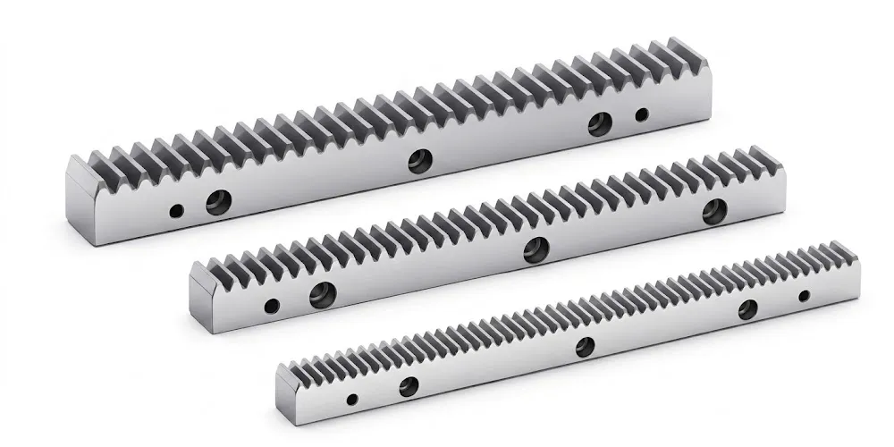
Matched helical gear rack and pinion sets for linear motion applications — positioning tables, rolling mill entry guides, and industrial automation systems. The helical rack and pinion configuration delivers the same smooth, progressive tooth engagement as a rotary helical gear set, with the added benefit of unlimited travel length through bolt-and-butt rack joining.
About Our Workshop
With more than a decade of hands-on experience in mechanical transmission manufacturing, our facility has built its reputation by delivering precision gear components that perform reliably in the most demanding environments worldwide. Our product range spans agricultural gearboxes, worm gear reducers, planetary gear drives, power take-off shafts, hydraulic cylinders, gears, chains, and electric motors — all produced under a single roof and managed through an ISO 9001:2015-certified quality management system.
We design and produce a broad array of industrial and agricultural gearboxes and mechanical assemblies using ductile iron, cast iron, cast steel, precision cast steel, and cast aluminum as base materials. Our machining shop handles gears, sprockets, worm gear sets, pulleys, worm shafts, and both standard and non-standard mechanical parts. This breadth of manufacturing capability means that when you source a double helical gear from us, you can simultaneously order every other gear component in the same drive train — eliminating the coordination overhead of managing multiple helical gear suppliers and ensuring dimensional compatibility at the assembly level.
As a dedicated helical gear factory 그리고 helical manufacturer with global export experience, we ship regularly to Australia, the UK, the Netherlands, Brazil, Canada, South Korea, Colombia, and beyond. Our engineering team can work from a customer drawing, a worn part sample, or a performance specification — and provide DFM feedback to optimise the gear design for cost-effective manufacture without compromising mechanical integrity.
Need a Custom Double Helical Gear Quote?
Send us your technical drawing or specification — our engineering team will review and respond with a detailed proposal within 24 hours. No minimum order quantity for custom made helical gears with validated specs.
자주 묻는 질문
Q1. How does a double helical gear eliminate axial thrust in a heavy-duty rolling mill drive?
에이 double helical gear achieves this by pairing two helical tooth rows of identical helix angle but opposite hand — one left-hand and one right-hand — on the same gear body. When the gear transmits torque, each half generates an axial thrust force in the opposite direction to the other. Because both rows carry the same load simultaneously, the forces are equal in magnitude and cancel each other out completely at the shaft. In a rolling mill where pinion bearing thrust loads can reach hundreds of kilonewtons, this self-cancelling behaviour directly translates into longer bearing life, reduced lubricant consumption, and fewer unplanned maintenance shutdowns during a rolling campaign. This is why double helical gear applications in steel rolling mills have been the dominant configuration for large mill stands globally for decades.
Q2. What makes 42CrMo alloy steel the preferred helical gear material for high-load industrial applications?
42CrMo — known internationally as AISI 4140, JIS SCM440, or DIN 42CrMo4 — is the go-to helical gear material in heavy industry for several interconnected reasons. The chromium content raises hardenability, meaning the steel can be through-hardened in larger section sizes. The molybdenum content improves high-temperature toughness and prevents temper embrittlement during the hardening-and-tempering cycle. After high-frequency quenching, tooth surfaces reach 50–55 HRC — sufficient to resist pitting under high contact stresses — while the core retains the toughness needed to absorb impact loads from mill cobbles or agricultural shock events. It is also widely available, economically priced relative to specialty grades, and covered by a large body of fatigue data that designers can reference confidently during double helical gear design.
Q3. Which industries and sectors worldwide most commonly use double helical gears in their main drive systems?
The most frequent double helical gear uses span several capital-intensive sectors. Steel and aluminium rolling mills are the primary users — the combination of extreme torque, continuous operation, and the unacceptability of unplanned downtime makes the self-balancing design almost mandatory. Marine propulsion gearboxes on ocean-going vessels represent another major category, valued for both power density and low acoustic signature. Cement kiln and ball mill drives, large petrochemical compressor trains (particularly those covered by API 613), and power generation turbine reduction gearboxes also rely heavily on double helical gear configurations. Agricultural machinery manufacturers serving Australian grain farming, European forage harvesting, and North American row-crop operations increasingly specify double helical gears in central drive assemblies where shock-load resistance and long service intervals are critical.
Q4. How are double helical gears manufactured, and what is the typical helical gear machining sequence from raw blank to finished gear?
Helical gear manufacturing process for the EP-Rolling Mill series starts with a forged or rolled alloy steel blank, verified against the material certificate. The blank is rough turned to within approximately 2–3 mm of the finish size, then pre-heat-treated (normalise or quench-and-temper) to refine the microstructure before tooth cutting. Semi-finish turning brings the blank to the tooth-cutting stage. Helical gear milling or gear hobbing then cuts both helical tooth rows — the cutter direction is reversed between the two halves to generate the opposing helix. High-frequency quenching follows, targeting 50–55 HRC at the tooth surface. For precision assembly parts, post-quench helical gear machining — specifically tooth flank grinding — corrects any heat-distortion to achieve the specified DIN precision class. Final dimensional inspection covers pitch error, tooth profile, helix angle, runout, and bore geometry. The entire helical gear manufacturing process is documented and traceable under our ISO 9001:2015 quality system.
Q5. Where can manufacturers in Australia, the UK, Canada, or Brazil source reliable custom made helical gears with short lead times and verified material certifications?
Sourcing reliable custom made helical gears internationally requires a helical gear supplier with both manufacturing depth and documented quality systems. Our facility ships regularly to industrial buyers in Australia, the United Kingdom, the Netherlands, Canada, Brazil, South Korea, Colombia, and other markets. Every order is accompanied by a material mill certificate, a dimensional inspection report, and a heat treatment hardness record. Lead times for custom double helical gear orders depend on size and complexity — but for module sizes up to M20 and outside diameters up to approximately 1,500 mm, we typically quote 4–8 weeks from drawing approval to shipment, packed in export-rated wooden cases. For repeat orders or standing call-off agreements, we can maintain semi-finished blanks in stock to reduce response time. Contact our technical team with your drawing or sample for a specific lead-time commitment.
편집자: PXY