
TECHNICAL MAINTENANCE GUIDE
A field-level and workshop guide to slip clutch torque calibration on round baler PTO shafts — covering how friction clutches work, how to set them accurately, and the real cost of running outside the specified range.
The slip clutch fitted to a round baler PTO shaft is the single component responsible for preventing a blockage event from destroying the baler gearbox. When it is calibrated correctly, it releases cleanly at the threshold torque set by the baler manufacturer — absorbing the peak load rather than allowing it to propagate through the driveline. When it is set outside that range, the consequences are not neutral. A clutch set too tight transfers damaging peak torque to the gearbox; one set too loose degrades its own friction surfaces through repeated nuisance slipping and eventually fails to protect the gearbox at all. Neither failure mode is obvious in normal operation — both look like a clutch that is simply doing its job until something more expensive breaks.
This guide covers the mechanical principles behind friction slip clutch operation on the round baler PTO shaft, the material construction of the clutch assembly, and the step-by-step procedure for setting and verifying torque across the operating season. The information applies to the principal baler platforms used globally — including John Deere, CASE IH, Krone, and New Holland round balers — and to the range of Series 4, 6, and 8 PTO driveshafts fitted to these machines.
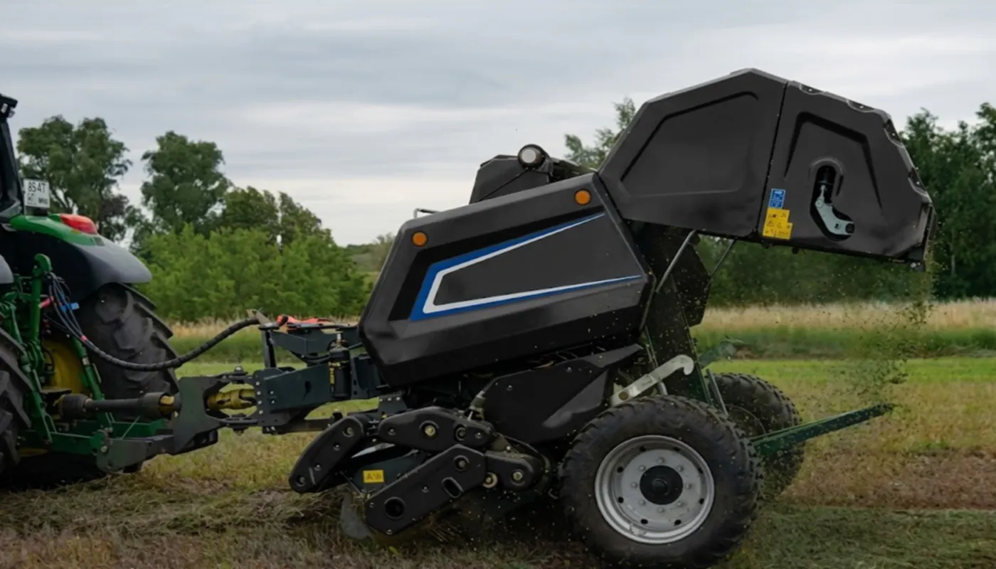
How a Friction Slip Clutch Works on a Round Baler PTO Shaft
A friction slip clutch is a torque-limiting device installed between the tractor PTO output and the baler gearbox input. It transmits torque through a stack of alternating friction discs and steel pressure plates compressed by a set of calibrated springs. Under normal baling conditions — a uniform windrow, steady ground speed, consistent crop density — the spring-clamped disc stack generates enough friction to transmit the full drive torque without any relative slip between the clutch halves. The shaft turns as a rigid assembly.
When an overload occurs — a sudden dense clump, a pickup rotor blockage, or an engagement event with the baler partially jammed — the torque applied to the shaft briefly exceeds the spring clamping force times the friction coefficient of the disc faces. At that point the disc stack slips, allowing the tractor side of the clutch to rotate independently from the baler input side. This slip event absorbs the peak torque as heat in the friction surfaces rather than transmitting it as a force spike to the gearbox input bearing. The slip lasts only as long as the overload persists; once the obstruction clears, the clutch re-engages and baling continues without operator intervention. This characteristic — self-resetting without stopping the tractor — is what makes the friction slip clutch the preferred overload device on modern high-output round baler PTO shaft assemblies, compared to the shear bolt alternative that requires a manual replacement after every blockage event.
Manufacturing Construction of the Slip Clutch Assembly
The clutch assembly fitted to a round baler PTO shaft consists of five functional subsystems: the clutch housing, the friction disc stack, the pressure plates, the compression spring pack, and the adjustment collar with locking nut. Each subsystem plays a specific role in determining the clutch’s release torque and its consistency over a working season. The quality of manufacture at each level directly affects how reliably the clutch releases at its set point — and how long it maintains that setting before re-calibration is needed.
Clutch Housing
Cast or forged steel body that encloses the disc stack and carries the spring retention seats. Housing flatness and parallelism at the disc contact faces determines how evenly the clamping force distributes across the friction disc area.
Friction Discs
Sintered bronze or organic composite discs that alternate with steel plates. The friction material determines the coefficient of friction, thermal stability under repeated slip events, and wear rate. Sintered bronze discs offer better thermal performance in wet silage conditions; organic composite discs provide a higher and more consistent friction coefficient in dry hay environments.
Steel Pressure Plates
Hardened steel plates that interleave with the friction discs. Surface finish quality on the contact face controls the initial break-in behaviour and the long-term stability of the friction coefficient. Rough or uneven plate surfaces cause inconsistent release torque during the first operating hours of a new clutch.
Compression Spring Pack
A set of disc springs or coil springs that apply the clamping force to the disc stack. Spring rate and free height determine the torque adjustment range. Springs that have fatigued — losing free height over a season of repeated slip events — reduce effective clamping force below the set point without any visible external indication.
Adjustment Collar
A threaded collar on the clutch body that compresses or releases the spring pack when rotated. The torque setting is proportional to the collar’s thread position. A locking nut or securing pin prevents the collar from rotating during operation, maintaining the set clamping force throughout the working day.
Material System: Component Specifications
| Компонент | Материал | Key Property | Wear / Failure Indicator |
|---|---|---|---|
| Friction discs | Sintered bronze or organic composite | Stable friction coefficient, thermal tolerance | Glazed surface, thickness below minimum |
| Steel pressure plates | Закаленная легированная сталь | Surface flatness, hardness | Scoring, blue heat discolouration |
| Compression springs | Chrome-silicon or chrome-vanadium spring steel | Free height stability over heat cycles | Reduced free height, lower clamping force |
| Clutch housing | Forged or cast steel | Housing flatness, thread integrity | Thread wear on adjustment collar |
| U-joint cross (PTO shaft) | 20CrMnTi carburised steel | Fatigue strength, surface hardness 58–62 HRC | Radial play in yoke ear, clicking at engagement |
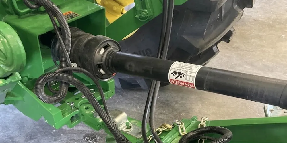
Slip Clutch Torque Setting Reference by Baler Platform
The correct slip clutch release torque is defined by the baler manufacturer, not by the shaft manufacturer or the operator. It is set to protect the weakest link in the driveline — typically the baler gearbox input shaft or the first-stage gear pair — while allowing enough torque headroom to handle normal crop load variation without nuisance slipping. The following reference table provides approximate torque ranges for common round baler platforms. Always confirm the exact specification in the baler’s operator and parts manual before making adjustments, as these figures vary between model years and market configurations.
| Baler Platform | PTO Speed | Clutch Type | Approx. Release Torque Range | Re-check Interval |
|---|---|---|---|---|
| John Deere 469 / 569 | 1000 RPM | 80° friction slip clutch | 800–1,400 Nm | Every 40–50 hours |
| CASE IH RB344 / RB454 / RB564 | 540 / 1000 RPM | Friction slip clutch | 700–1,200 Nm | Every 40 hours |
| Krone Round Balers (KR/Comprima series) | 1000 RPM | Wide-angle friction clutch | 900–1,600 Nm | Every 50 hours or after blockage |
| New Holland BR7050 / BR7060 | 1000 RPM | Friction slip clutch | 850–1,450 Nm | Every 40–50 hours |
| New Holland 630 / 648 | 540 об/мин | Shear bolt or slip clutch | 500–900 Nm (where clutch fitted) | Every 30–40 hours |
Step-by-Step Slip Clutch Calibration Procedure
Slip clutch calibration is not a task that requires specialised workshop equipment — it can be performed accurately in the field with basic hand tools and a torque reference from the baler manual. The key is to follow a consistent sequence so that each adjustment step is properly verified before the shaft returns to service. Skipping the verification step is the most common reason a clutch is incorrectly set even after an adjustment has been made.
Step 1 — Disengage and isolate: Disengage the tractor PTO and allow the driveshaft to come to a complete stop. Remove the shaft from the baler input connection if possible to provide safe access to the clutch adjustment collar. Never attempt to adjust the clutch with the shaft spinning.
Step 2 — Inspect the disc stack: Before adjusting the spring preload, confirm that the friction discs are not glazed, cracked, or below minimum thickness. A glazed disc — recognisable by a smooth, shiny surface across the friction face rather than the original matte or sintered texture — cannot develop a consistent friction coefficient regardless of spring clamping force. Replace glazed discs before re-calibrating.
Step 3 — Check spring free height: If the clutch has been in service for more than one full baling season, check the compression springs against the manufacturer’s new-part free height specification. Springs that have lost more than 5% of their original free height will not generate the specified clamping force even at full collar engagement. Replace as a set, not individually.
Step 4 — Adjust the collar: Refer to the baler operator’s manual for the specified collar thread position or torque setting. Tighten or loosen the adjustment collar incrementally — typically in quarter-turn increments — to reach the target clamping force. The manual will typically specify the clutch release torque in Nm and the corresponding spring deflection or collar gap dimension that achieves it.
Step 5 — Verify under load: With the shaft reconnected and the tractor PTO running at the specified operating speed, perform a controlled blockage simulation by briefly jamming the baler pickup rotor. Observe whether the clutch releases cleanly and re-engages smoothly once the rotor is freed. A clutch that does not release under a simulated blockage is set too tight; one that slips during a normal crop pass through an even windrow is set too loose. Adjust the collar by one quarter turn at a time and retest until the behaviour is correct.
Round Baler PTO Shaft with Integrated Slip Clutch for Krone Balers
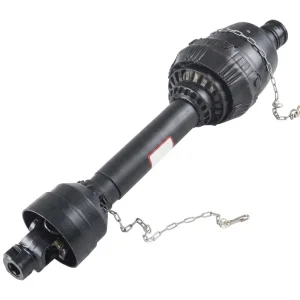
EP PTO Shaft for Krone Round Balers
A direct-fit round baler PTO shaft replacement for Krone round baler platforms including the KR and Comprima series. The assembly incorporates a wide-angle friction slip clutch factory-set within the standard Krone release torque range, using a sintered bronze disc stack for thermal stability across silage and hay applications. The U-joint crosses are manufactured from 20CrMnTi carburised steel with precision-ground 52100 bearing cups. Front yoke connection accommodates 1-3/8 in. × 21 spline tractor outputs as required for 1000 RPM Krone baler operation. The HDPE guard assembly carries CE certification. Compatible for use across European markets including Germany, France, the Netherlands, and Denmark where Krone round balers are most widely operated.
What Happens When the Torque Setting Is Wrong
Clutch Set Too Tight
When the slip clutch release torque is set above the baler gearbox’s rated input torque, every blockage event that the clutch fails to absorb sends a full stall-torque spike into the gearbox. The first component to absorb this energy is typically the input shaft bearing — a needle or ball-race bearing not designed for axial shock loading. After a number of these events, the bearing cage fractures, the input shaft develops play, and gear tooth contact becomes uneven. The gearbox may remain functional for the remainder of the season before catastrophic failure, but the bearing damage is accumulating with each event and is not reversible without full gearbox disassembly. In CASE IH and John Deere 9-Series round balers, gearbox input bearing replacement is a multi-hour workshop task that typically follows a season of running with an over-tightened clutch on the round baler PTO shaft.
Clutch Set Too Loose
A clutch that releases below the normal baling torque slips during routine operation — not just during blockage events. Each unintended slip event heats the friction disc faces. At temperatures above approximately 180°C the organic or sintered bronze friction material begins to lose its surface texture and glazes — developing a hard, smooth surface that has a significantly lower and more variable friction coefficient than the original material. A glazed clutch will release inconsistently: sometimes at the correct torque, sometimes well below it, and during a real high-torque blockage event it may release far below the gearbox protection threshold, allowing the baler to run on partial power without fully absorbing the peak. Operators often interpret nuisance slipping as the shaft being under-spec for the baler, when the actual problem is a clutch whose friction discs need replacement and whose spring preload needs upward adjustment.
Seasonal Clutch Maintenance Schedule
Slip clutch maintenance is not a once-per-season task. The friction disc stack wears progressively, the compression springs lose a small amount of free height with each heat cycle, and the adjustment collar’s locking mechanism can vibrate slightly loose over many hours of operation. A structured maintenance schedule — tied to operating hours rather than calendar dates — keeps the clutch within its specified release torque range throughout the baling season without requiring a full disassembly each time.
| Interval | Task | Tool Required | Action if Out of Specification |
|---|---|---|---|
| Pre-season | Full clutch disassembly, disc inspection, spring free-height check, housing flatness check | Vernier caliper, feeler gauge | Replace discs and/or springs as needed; re-calibrate collar |
| Every 40–50 hours | Collar locking nut torque check; functional release test under controlled blockage | Torque wrench, baler manual | Adjust collar by quarter-turn increments; retest |
| After any major blockage | Visual disc inspection for glazing or cracking; functional release test | Visual inspection only | Replace glazed discs; re-calibrate |
| End of season | Disassemble, clean, regrease disc splines, check for season-end wear | Degreaser, EP grease | Note components requiring replacement before next season |
| Any time nuisance slipping observed | Identify root cause — over-loose setting or glazed discs — before adjusting collar | Visual inspection | Replace discs if glazed; adjust spring preload if discs are acceptable |
Related Driveline Components
The slip clutch on a round baler PTO shaft does not operate in isolation. Its release torque must be matched to the input torque rating of the baler gearbox on one side and coordinated with the universal joint capacity of the driveshaft on the other. Sourcing the shaft, gearbox, and any universal driveline components from a single supplier range simplifies this coordination and reduces the risk of a mismatched torque rating in the system.
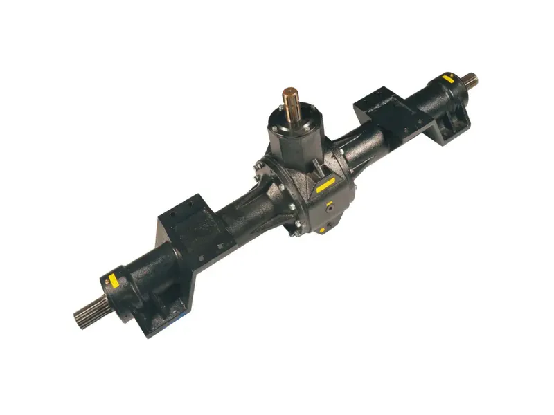
The baler input gearbox defines the maximum torque that the driveline — including the round baler PTO shaft and its slip clutch — should ever transmit under blockage conditions. Knowing the gearbox input shaft’s rated torque capacity is the starting point for setting the slip clutch correctly. When the gearbox itself has been damaged by a season of over-tight clutch operation, replacing it alongside a recalibrated shaft assembly restores the complete driveline to its designed protection hierarchy — shaft clutch protects the gearbox, gearbox protects the baler mechanism.
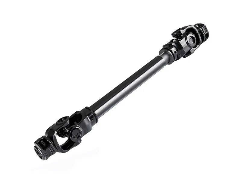
Универсальный карданный вал отбора мощности
For operations running mixed baler fleets or changing tractor-baler combinations between seasons, a universal PTO driveshaft with a factory-calibrated friction clutch provides a consistent torque protection baseline across different pairings. The Series 6 universal shaft includes the same sintered bronze disc stack and adjustment collar as the model-specific versions, allowing the operator to re-calibrate to any baler’s specified release torque without sourcing a model-specific clutch kit separately. Cross-series repair components — disc sets, springs, guard assemblies — remain interchangeable within the same series group.
О производителе
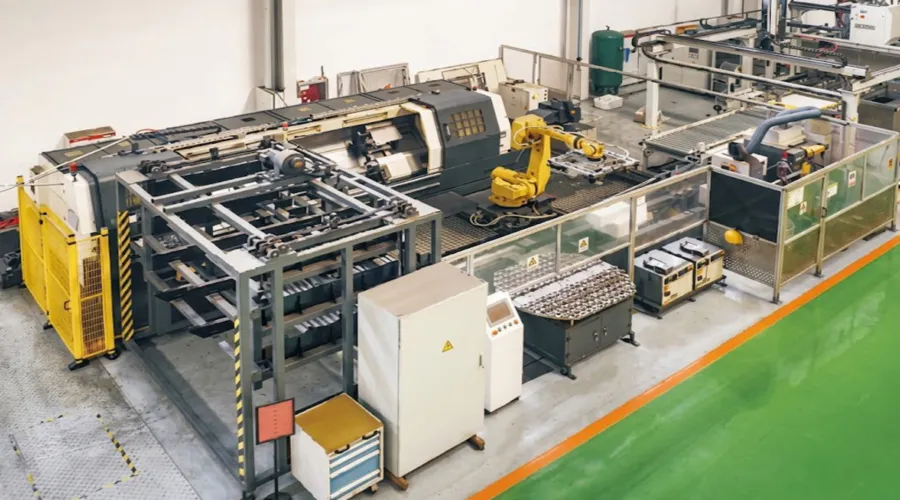
The manufacturing catalogue spans agricultural gearboxes, worm gear reducers, planetary gear drives, power take-off shafts, hydraulic cylinders, gears, chains, and motors — all produced under ISO 9001:2015 quality management certification covering raw material intake, machining, assembly, and final inspection. Gearbox housings and structural assemblies are produced in ductile iron, cast iron, cast steel, precision cast steel, and cast aluminium, with grade selection determined by the load, thermal, and environmental requirements of each application. Custom and non-standard components — sprockets, worm gears, precision shafts, pulleys, and engineered assemblies — are manufactured to customer drawings or application descriptions, with engineering review and written quotation returned within 24 hours of a technical inquiry.
Мастер-класс



Часто задаваемые вопросы
Редактор: PXY