
FIELD SAFETY & MAINTENANCE GUIDE
A step-by-step operator guide to safe disconnection of a round baler PTO shaft during blockage clearing, mid-season inspection, or emergency field replacement — with notes on the mechanical components involved and what to check before reinstalling.
Removing a round baler PTO shaft in the field is one of those tasks that looks straightforward until something goes wrong — a stuck lockback collar, a guard that will not retract, or a shaft that has been run with corrosion in the yoke bore and now requires significant effort to free. Most PTO shaft incidents occur not during baling but during connection and disconnection — the points at which operators are working in close proximity to the shaft with the guard open or partially displaced. A methodical approach that confirms the shaft has fully stopped rotating, the tractor is secured, and the shaft components are safely supported before any connection is broken eliminates the majority of these risks.
This guide covers the complete field removal sequence for a round baler PTO shaft, the mechanical components involved in each disconnection step, what to inspect while the shaft is off the baler, and how to reinstall correctly. The procedure applies to the full range of agricultural PTO shafts used on round baler platforms including John Deere, CASE IH, Krone, and New Holland balers — with notes on the specific collar and guard mechanisms used on different shaft series.
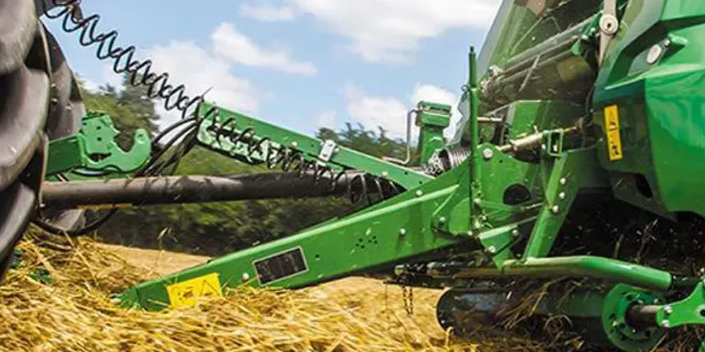
Before You Start: Safety Prerequisites That Cannot Be Skipped
A PTO shaft that appears stationary can still rotate if the tractor engine is running or if internal spring tension in the slip clutch is transmitted when the baler mechanism is disturbed. Every field removal procedure must begin with three confirmed conditions before any part of the shaft or guard is touched. These are not precautions to be abbreviated when time is short — they are the steps that separate a routine disconnection from a serious injury event.
1 — Engine off, PTO disengaged: Disengage the tractor PTO lever and switch off the engine. Do not rely on the PTO lever alone — an engine-off shutdown eliminates the possibility of accidental PTO engagement by a second person or by inadvertent lever movement while working around the shaft. On tractors with electronic PTO engagement, confirm the dash indicator shows the PTO as disengaged before exiting the cab.
2 — Shaft fully stopped: Wait until the shaft has come to a complete standstill before approaching it. On baler platforms with significant flywheel mass in the pickup rotor or bale formation rollers, rotational inertia can keep the shaft turning for 10–30 seconds after PTO disengagement. Confirm visual stillness — do not rely on sound alone, as bearing noise continues after rotation stops.
3 — Tractor handbrake and baler chocked: Apply the tractor parking brake and, where ground slope is present, place a wheel chock behind the baler wheels before working under or beside the driveline. A tractor that rolls while the operator is working at the shaft connection points is a hazard independent of PTO engagement.
Understanding the Round Baler PTO Shaft Before Disconnecting It
A round baler PTO shaft connects the tractor’s PTO output stub to the baler’s input gearbox shaft via two connection points — one at each end. The tractor end uses a splined yoke engagement secured by a spring-loaded lockback collar; the implement end connects to the baler gearbox input through a similar collar or, on some Krone and CASE IH platforms, a flange coupling. Between the two connection points sits the telescoping shaft body — two overlapping steel tubes that slide to compensate for distance changes — and the guard assembly, which consists of HDPE tubes and end cones that enclose the rotating shaft and are themselves secured to the yoke housings by bearing rings that allow the guard to remain stationary while the shaft rotates inside it.
Knowing which type of implement-end connection your baler uses before attempting removal prevents the most common disconnection error: attempting to pull the shaft free from the baler gearbox input before releasing the collar or unbolting the flange. On lockback collar connections, the collar must be depressed and held while the shaft is pulled back along the input shaft axis — if the shaft is pulled sideways or at an angle while the collar is engaged, the collar mechanism can jam and require significant force or a hammer to free. Taking thirty seconds to identify the connection type before applying force saves significant time and prevents damage to the yoke bore.
Manufacturing Construction: The Components You Are Working With
Lockback Collar
A spring-loaded ring seated around the yoke neck. When depressed, it retracts the locking balls or spring-loaded pins that engage a groove on the PTO stub or baler input shaft, releasing the connection. The spring must be depressed fully before the shaft is pulled — partial depression leaves one or more balls partially engaged, and pulling under this condition scores the PTO stub groove.
Guard Bearing Ring
A low-friction bearing mounted between the rotating yoke housing and the stationary guard end cone. This ring allows the guard to remain stationary while the shaft turns inside it. When the guard cone is pulled back to access the lockback collar, the bearing ring can fall free if the cone is removed completely — retain it and confirm it is replaced in the correct orientation when reinstalling.
Telescoping Tube Splines
The inner tube slides within the outer tube along a profiled spline — lemon or star cross-section on agricultural series shafts. If the tubes have not been greased recently, they may resist separation under the shaft’s own weight. Never use the tractor’s drawbar or the baler tongue as a lever to force tube separation — this distorts the tube profile. Lubricate and work the tubes manually.
U-joint Crosses and Bearing Cups
The universal joint at each end of the shaft transfers torque through a hardened steel cross held in the yoke ears by precision bearing cups retained with circlips. These components are not involved in the disconnection sequence, but they should be checked for radial play while the shaft is off the baler — a cross that has developed play is significantly easier and safer to replace on a workbench than in the field.
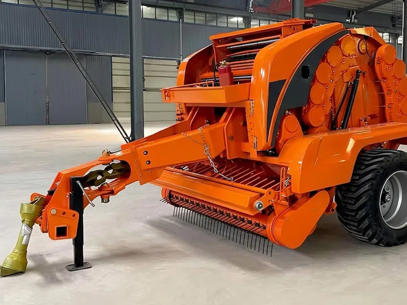
Step-by-Step Field Removal Procedure
The following sequence covers the most common round baler PTO shaft configuration — a telescoping shaft with lockback collar connections at both ends and an HDPE guard with sliding end cones. Where your baler uses a flanged implement-end connection, step 4 is replaced by unbolting the flange coupling. Confirm the connection type at the implement end before starting.
| Step | Action | Common Error to Avoid |
|---|---|---|
| 1 | Engine off, PTO disengaged, handbrake applied — confirm all three before approaching the shaft. | Assuming the shaft is stopped because the baler is quiet; inertia can keep the shaft turning silently for up to 30 seconds. |
| 2 | Slide the guard end cone at the tractor end rearward along the guard tube to expose the lockback collar behind it. | Pulling the cone off completely rather than sliding it back — the bearing ring inside the cone can fall free and be lost in crop residue. |
| 3 | With one hand, depress the lockback collar fully rearward until you hear or feel the locking balls disengage from the PTO stub groove. | Partial collar depression — the shaft will not slide off and forcing it scores the PTO stub’s locking groove. |
| 4 | While maintaining collar depression, slide the tractor-end yoke straight rearward along the PTO stub axis until it clears the stub completely. | Pulling at an angle while the collar is depressed — angular pull jams the collar balls against the stub shoulder, requiring hammer work to free. |
| 5 | Support the tractor end of the shaft — do not allow it to drop. The shaft’s weight hanging from the implement-end connection stresses the baler gearbox input shaft and bearing. | Letting the shaft hang unsupported from the baler input; the bending load can crack the gearbox input bearing cage over repeated removal events. |
| 6 | Move to the implement end. Slide the guard cone back to expose the baler-end lockback collar or flange coupling. | Attempting to disengage the implement end with the guard still covering the collar — the guard restricts hand access to the collar ring. |
| 7 | Depress the implement-end collar and slide the yoke straight off the baler input shaft axis, supporting the shaft weight with the other hand or a support stand. | Same as step 4 — angular pull on a partially engaged collar scores the baler input shaft’s locking groove and may require a new input shaft. |
| 8 | Place the removed shaft on a clean, dry surface — not directly on soil or wet crop residue. Cover both yoke ends with the guard cones or rags to prevent debris entry into the U-joint bearing cups. | Leaving open yoke bores facing down in wet conditions — soil and moisture ingestion in the bearing cup contact zone begins within minutes. |
Material System: What to Check While the Shaft Is Off
A round baler PTO shaft removal in the field is the best opportunity of the season to inspect components that cannot be accessed while the shaft is connected and running. The following checks take five to ten minutes and can prevent a second, more disruptive field stop later in the cutting cycle.
| عنصر | مادة | What to Check | Action if Faulty |
|---|---|---|---|
| U-joint crosses | 20CrMnTi carburised | Grip each cross and check for radial play in the bearing cups. Any detectable movement means the cups are worn. | Replace cross and bearing cup kit before reinstalling |
| Bearing cups | 52100 bearing steel | Look for pitting, spalling, or blue heat discolouration on the cup bore surface visible through the yoke ear opening. | Replace full cross kit — individual cups are not sold separately for in-service repair |
| Telescoping tube profiles | Q345 cold-drawn steel | Work the shaft through its full extension range by hand. Stiff or binding action with light resistance indicates dry splines or early corrosion. Clean and regrease. | Grease and re-check; if binding persists after greasing, replace shaft |
| Lockback collar springs | Chrome-silicon spring steel | Depress and release both collars; each should return sharply and fully to its extended position. Sluggish return means a fatigued spring that may not lock the shaft correctly on reinstallation. | Replace collar spring kit before reinstalling |
| Guard tube and cones | UV-stabilised HDPE | Check for cracks, broken retention rings, or missing end caps. A guard with structural cracks does not protect the operator and collects crop material against the rotating shaft, creating a fire hazard in dry conditions. | Replace guard section or complete guard assembly |
| Weld seam at yokes | Q345 tube / SAE 1045 yoke | Visually inspect the weld toe at each yoke connection for surface cracking or discolouration. Weld toe cracks propagate under cyclic load and can cause sudden shaft separation under working conditions. | Remove from service immediately; replace shaft assembly |
When Inspection Shows Replacement Is Needed: EP Round Baler PTO Shaft for John Deere 469 / 569
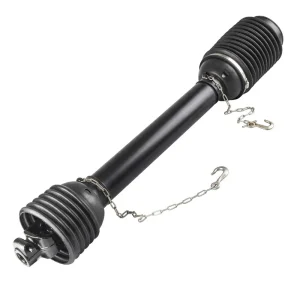
EP Round Baler PTO Shaft — John Deere 469 / 569 Series
When field inspection reveals a cross with radial play, a cracked guard, or a weld seam crack that takes the existing shaft out of service, a correctly specified replacement round baler PTO shaft needs to be on-hand or quickly sourced. This direct-fit replacement for the John Deere 469 and 569 platforms is built to the CAT4 / CAT5 CV specification with 20CrMnTi carburised crosses, precision-ground 52100 bearing cups, and a UV-stabilised HDPE guard carrying CE certification. The lockback collars on both ends use the same spring-and-ball mechanism as the original John Deere specification, allowing field installation without modification. Front yoke accommodates 1-3/8 in. × 6 and 1-3/8 in. × 21 spline tractor outputs.
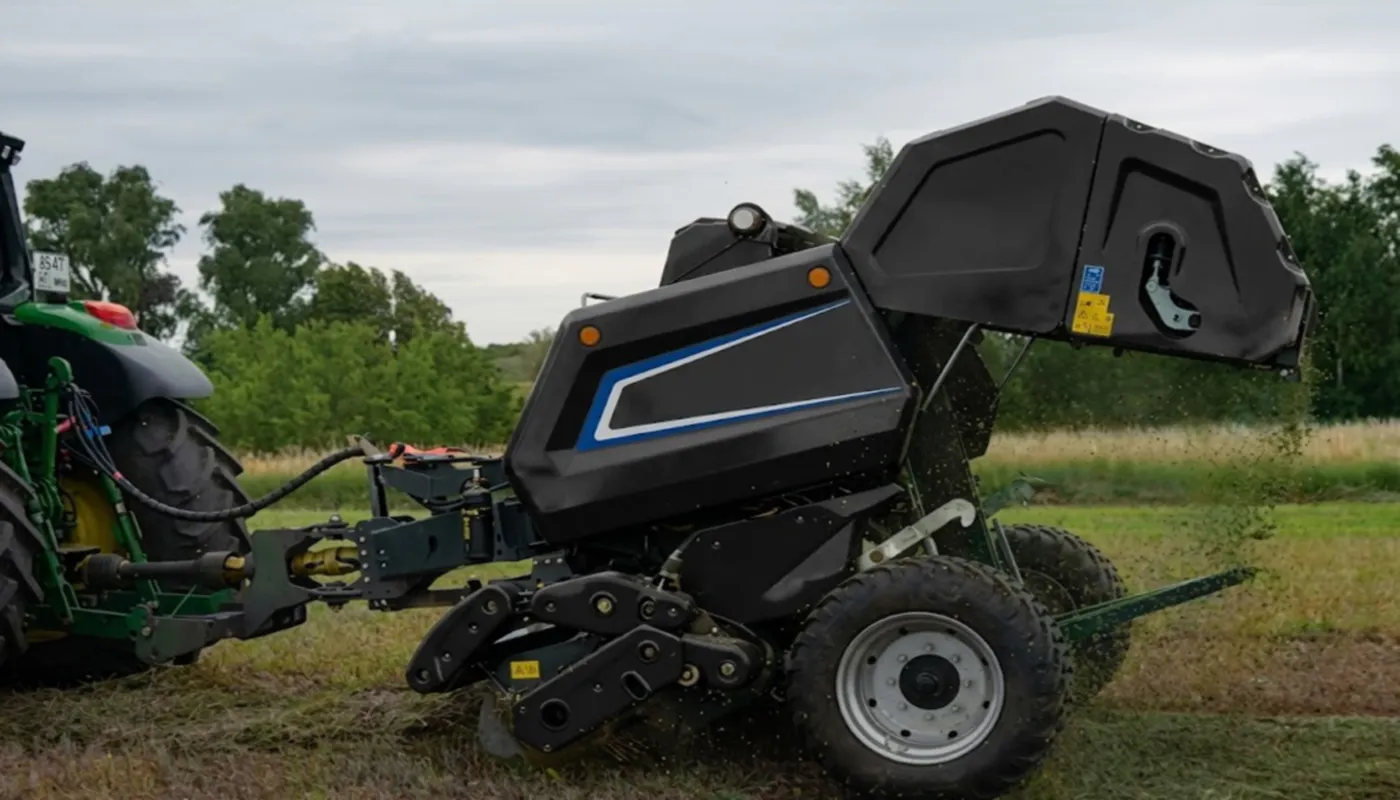
Reinstalling the Round Baler PTO Shaft Correctly
Reinstallation follows the removal sequence in reverse, with four additional steps that are commonly missed on a field reinstall done under time pressure. Each of these steps takes less than a minute and prevents the most common post-reinstall problems: a shaft that connects but does not lock, a guard that is not seated correctly and contacts the rotating shaft, or a telescoping tube that is adjusted to the wrong working length for the hitch distance.
Check telescoping length before connecting
Position the tractor at the working hitch distance from the baler — straight line, level ground — and confirm the shaft sits at roughly the mid-point of its telescoping range. A shaft at full extension or near full collapse at the working distance will bind or bottom out during field operation. Adjust the tractor drawbar position if needed before connecting.
Align the splines before pushing home
Before pushing the yoke onto the PTO stub or baler input shaft, rotate the shaft slightly by hand until the spline teeth align with the stub splines. Forcing a misaligned yoke into a splined stub damages both the yoke and the stub spline faces. On 21-spline connections the tooth spacing is finer and alignment is more critical than on 6-spline connections.
Confirm the lockback collar has clicked locked
After pushing the yoke fully onto the stub, release the collar and try to pull the shaft back off by hand without depressing the collar. If the shaft pulls back even slightly, the locking balls have not seated in the stub groove. Remove and reconnect — a shaft that is partially engaged will disengage under the first torsional shock load from a blockage event.
Seat the guard cones and confirm clearance
Slide the guard cones back into position over the yokes and confirm that the bearing ring is seated correctly in each cone before it is pushed into its retention collar. With the shaft at the working angle, visually confirm that no part of the guard tube contacts the yoke housing during manual rotation through the operating angle range. A guard that contacts the rotating shaft generates heat and can ignite dry crop material within minutes of operation.
When the Shaft Will Not Release: Field Troubleshooting
A round baler PTO shaft that resists disconnection after the collar is depressed is almost always the result of one of three conditions: corrosion in the stub groove that prevents the locking balls from retracting fully, a bent or deformed yoke bore from a previous overload event, or crop material packed tightly around the collar ring that prevents full depression. None of these requires significant force to resolve if the correct approach is used.
Collar depressed but shaft will not slide: Apply penetrating fluid to the junction between the yoke bore and the PTO stub or baler input shaft and wait two to three minutes for it to work into the groove. Maintain collar depression and work the yoke with a gentle rotary motion — left and right through a few degrees — rather than pulling straight back. The rotary action frees the locking balls from any surface corrosion in the groove without scoring the stub.
Collar will not depress fully: Inspect the collar face for packed crop material, soil, or hardened old grease. Clean with a stiff brush and compressed air if available. If the collar spring has become jammed — evidenced by the collar moving part-way and stopping with no further spring resistance — do not force it. The locking ball has cocked against the collar seat; applying rotary movement to the shaft while maintaining collar pressure usually frees the ball and allows full collar travel.
Shaft free at one end but stuck at the other: Support the freed end of the shaft so it does not swing or fall while you work the stuck end. The shaft’s weight hanging at an angle once one end is free can push the still-engaged yoke into the stub at a slight angle, which jams the collar. Keep the shaft parallel to the stub axis throughout the removal process at the stuck end.
Related Driveline Components
After a field removal and inspection, the adjacent driveline components at each connection point — the baler input gearbox and the tractor-side PTO adapter or universal shaft — should be included in the inspection scope. A round baler PTO shaft that has been run to failure or near-failure has often transmitted loads beyond its rating to both connected components, meaning those components may also need attention before the baler returns to service.
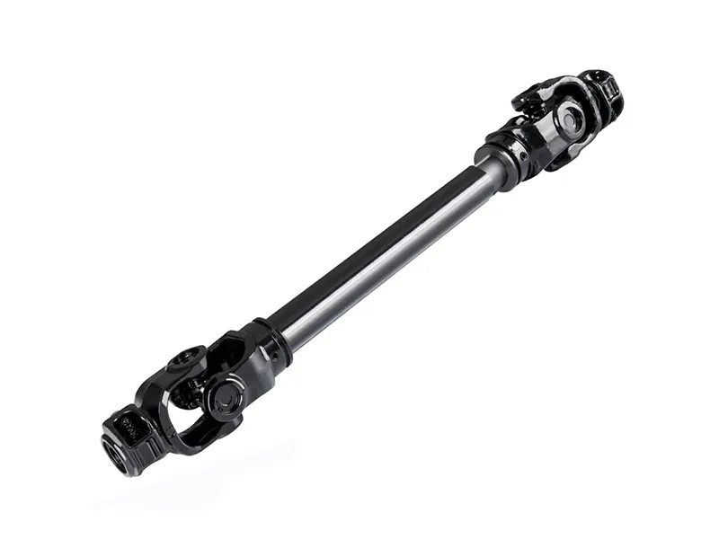
For operations that carry a spare shaft in the field tractor cab as an emergency replacement option, a universal PTO driveshaft in the correct series and length covers multiple baler models with a single stocked assembly. The lockback collar mechanism, guard assembly, and cross kit specification are identical to model-specific equivalents within the same series, allowing field installation using the same procedure as a model-specific replacement and the same inspection points at next service.
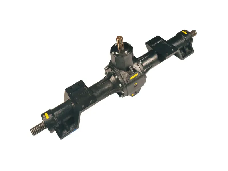
When the shaft is removed for inspection after a blockage event or shaft failure, the baler input gearbox stub — the shaft the implement-end yoke connects to — should be checked for groove wear from the lockback collar balls, shaft runout, and any sign of input bearing movement. A loose or noisy input shaft on the gearbox body indicates bearing wear that has been accumulating from a previous driveline specification error; addressing this at the same time as a shaft replacement prevents the new shaft from running against a damaged bearing from its first day of service.
نبذة عن الشركة المصنعة
The manufacturing catalogue covers agricultural gearboxes, worm gear reducers, planetary gear drives, power take-off shafts, hydraulic cylinders, gears, chains, and motors — all produced under ISO 9001:2015 certification applied across raw material intake, CNC machining, assembly, and final inspection stages. Gearbox housings and structural assemblies are produced in ductile iron, cast iron, cast steel, precision cast steel, and cast aluminium, with material selection matched to each application’s structural, thermal, and operational requirements. Custom and non-standard components — sprockets, worm gears, precision shafts, pulleys, and assemblies — are manufactured to customer drawings or application descriptions, with engineering review and written quotation returned within 24 hours of a technical inquiry or photograph of the component to be matched.
ورشة عمل




الأسئلة الشائعة
المحرر: PXY