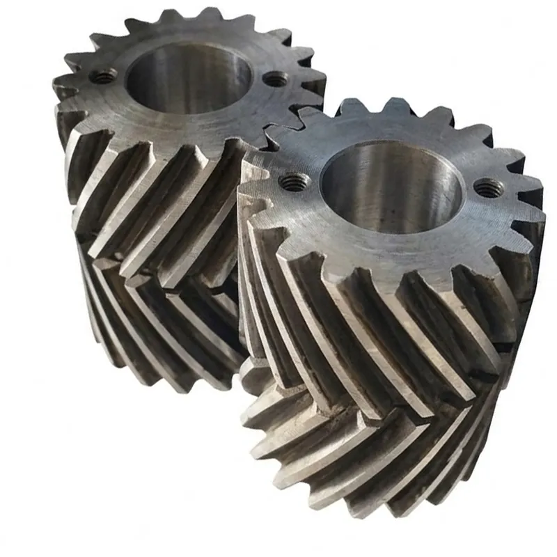
EP-Aircraft Double Helical Gear
ال EP-Aircraft Double Helical Gear is a high-precision transmission component engineered for demanding aerospace, automotive, and medical applications. Available in diameters from Φ3mm to Φ120mm and modules ranging from M0.15 to M2.0, these gears are manufactured from versatile materials including steel, bronze, aluminum, and POM to meet specific weight and strength requirements. Designed to eliminate axial thrust, the double helical configuration ensures smooth, quiet operation at high speeds. The gears adhere to stringent international meshing standards, including ISO6, JGMA 1, DIN 5/6, and AGMA 12/13, guaranteeing exceptional accuracy. Fully customizable via ODM/OEM services and certified under ISO 9001:2008/TS16949, each unit is vacuum-packed for protection. Ideal for critical systems requiring reliable torque transmission and minimal vibration.
EP-Aircraft Double Helical Gear — Precision-Engineered Double Helical Gear for Aerospace and High-Reliability Drive Systems
The EP-Aircraft Double Helical Gear represents the most demanding tier of our gear manufacturing programme. Designed to meet the dimensional, material, and quality standards required in aircraft auxiliary drives, rotorcraft transmission systems, and defence-grade mechanical assemblies, this double helical gear eliminates the axial thrust loads that constrain standard helical gear designs — while delivering the smooth, high-contact-ratio meshing that precision aerospace applications demand. With dimensions spanning Φ3 mm to Φ120 mm and modules from M0.15 to M2.0, this series covers the miniature and small-module double helical gear range used extensively in avionics actuation, fuel system drives, and aircraft instrument geartrains.
What Is a Double Helical Gear — and Why Does Aircraft Engineering Demand It?
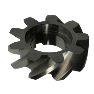
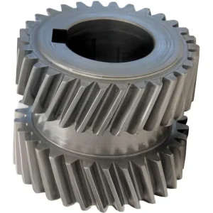
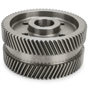
A double helical gear — sometimes referred to as a double helix gear or herringbone gear in broader engineering usage — is a parallel-shaft gear whose tooth geometry consists of two opposing helical sections cut on the same gear body, one with a right-hand helix and one with a left-hand helix. The result is a characteristic V-shaped or chevron tooth pattern. The mechanical consequence of this geometry is fundamental: the axial thrust forces generated by the two halves cancel each other within the gear body itself, producing net-zero axial load on the shaft bearings. This is the defining advantage of the double helical gear over standard single-helix helical gear designs, and it is the primary reason why high-power, high-speed aerospace and marine transmission engineers have favoured double helical configurations for over a century.
In aircraft applications specifically, where weight, space, and reliability margins are all simultaneously constrained, the double helical gear design solves a problem that otherwise requires heavy, complex thrust-bearing arrangements. By eliminating the need to react axial gear loads through dedicated thrust bearings, the gearbox designer can use smaller, lighter bearing assemblies — reducing total drive weight without compromising load capacity. For miniature aircraft auxiliary drive units, this space-efficiency advantage is often decisive. The EP-Aircraft series operates from M0.15, covering instrument drives and precision actuator mechanisms, up to M2.0 for larger actuation and accessory gearbox stages.
Understanding the difference between double helical vs herringbone gear is relevant here: in strict engineering usage, a true herringbone gear has continuous teeth that meet at the centreline without a groove, while a double helical gear has a relief groove at the centreline between the two helical sections to allow hobbing tool runout. The EP-Aircraft series is produced as a double helical gear with a centre groove, enabling the tooth-grinding operations that achieve the precision meshing grades — ISO6, AGMA 13, DIN 5 — required for flight-critical and defence applications. The double helical gear design in this configuration retains all the thrust-cancellation advantages of a herringbone while supporting the manufacturing accuracy that aerospace-grade gearing demands.
Five Key Advantages of the EP-Aircraft Double Helical Gear
Zero Net Axial Thrust — Bearing Load Eliminated
The opposing helix sections of a double helical gear cancel axial forces internally. Shaft bearings see only radial and tangential loads — not the axial thrust that a single-helix helical gear imposes and that requires larger, heavier thrust bearing arrangements. In aircraft auxiliary gearboxes, this thrust elimination is a direct weight-saving and reliability improvement simultaneously.
Highest Overlap Contact Ratio — Superior Load Distribution
With two helical tooth sets engaging simultaneously, the effective overlap contact ratio of a double helical gear is approximately double that of a comparable single-helix helical gear. More teeth in simultaneous mesh means lower peak tooth stress, extended fatigue life, and significantly lower transmission error — the root cause of gear noise and vibration in precision drives.
Multi-Material Flexibility — ODM/OEM Customisation
The EP-Aircraft series is available in a comprehensive material range: metal alloy steels, stainless steel helical gears, bronze, aluminium, POM, zinc, brass, and copper — selected by the customer based on operating environment, corrosion requirements, and weight constraints. Full ODM/OEM customisation is supported, including custom made helical gears produced to customer-supplied drawings or samples.
Aerospace-Grade Meshing Quality — ISO6 / AGMA 13 / DIN 5
The meshing grades certified for the EP-Aircraft double helical gear — ISO6, JGMA 1, JIS 6, AGMA 13, DIN 6, DIN 5, AGMA 12 — represent the upper tier of international gear quality standards. AGMA 13 in particular is rarely achievable without CNC tooth grinding and post-grind inspection using gear measurement equipment traceable to national standards. These grades are mandatory for flight-critical and military-grade gear applications.
Miniature Module Range — M0.15 to M2.0
From M0.15 for precision instrument drives through to M2.0 for auxiliary power unit accessory gearboxes, the EP-Aircraft series covers the complete miniature and small-module double helical gear range. Very few gear manufacturers are equipped to produce double helical gear design at M0.15 with consistent tooth geometry — this requires specialised hobbing tooling, precision temperature-controlled machining environments, and skilled gear measurement technicians.
Working Principle of the Double Helical Gear
The double helical gear transmits power between parallel shafts through two sets of involute helical teeth — one set cut with a right-hand helix angle, the other with a left-hand helix angle of equal magnitude. As the gear rotates, both helical sections engage with their counterparts on the mating double helical gear simultaneously. Each helical section generates an axial thrust force, but because the two sections have opposing helix directions, their axial forces act in opposite directions along the shaft axis and cancel at the gear hub. The shaft and its bearings experience only the radial (separating) force and the tangential (driving) force — not the axial component that engineers must accommodate with thrust bearings in single-helix helical gear arrangements.
The effective contact ratio of a double helical gear is the sum of the transverse contact ratio and twice the overlap contact ratio of a single helical section. In a well-designed double helical gear at a typical aerospace helix angle of 30°–35° per side, the total contact ratio exceeds 3.0 — meaning at least three tooth pairs are simultaneously carrying load at any point in the mesh cycle. This high contact ratio is why double helical gears achieve substantially lower transmission error than single helical gears of the same module, which is the quantitative explanation for their quieter, smoother operation in high-speed aircraft gearboxes.
The double helical gear design also provides a natural self-centering action: because the axial forces from the two tooth sets balance within the gear, the gear will shift axially to the position of minimum gear mesh force — effectively self-adjusting to the optimum contact position without requiring precision axial location of the gear on its shaft. This self-centering behaviour is particularly valuable in aircraft accessory drives where thermal expansion during flight operations can cause differential shaft growth between the gear housing and the rotating components.
Helical Gear Material Options & Manufacturing Process
The helical gear material selected for any aircraft double helical gear must satisfy a matrix of requirements that differ substantially from general industrial gear applications. In aerospace, the weight penalty of choosing a denser material is penalised across the entire service life of the aircraft. The corrosion resistance of the chosen material must survive the humidity cycling, altitude exposure, and fluid contamination environments of aircraft systems. And the fatigue strength of the material must be adequate for the high-cycle stress reversals experienced in continuous-duty accessory drives.
The EP-Aircraft series addresses this with a fully flexible helical gear material programme: alloy steels (including 20CrNiMoA, 42CrMo4, and aerospace-specific grades), stainless steel helical gears for corrosion-critical environments, aluminium alloy for weight-critical applications, bronze for self-lubricating and non-sparking requirements, POM engineering polymer for instrument drives requiring electrical isolation, and brass or copper for specific specialist applications. The manufacturing process — how helical gears are made at this precision level — follows a sequence of: material selection and bar/billet qualification → CNC turning → gear hobbing or milling (helical gear machining) → heat treatment (carburising, nitriding, or through-hardening as specified) → tooth grinding → dimensional inspection against drawing tolerances → surface treatment as required.
The tooth-grinding stage is what distinguishes this product from standard hobbed helical gear manufacturing. Machining helical gears to AGMA 13 or ISO6 requires CNC gear grinding machines with sub-micron positional resolution, temperature-controlled workholding, and traceable measurement — capabilities that very few helical gear manufacturers worldwide possess for the miniature module range (M0.15–M2.0). The result is a double helical gear that meets the surface finish, profile accuracy, pitch accuracy, and runout specifications demanded by aviation and defence procurement specifications globally.
Technical Specifications — EP-Aircraft Double Helical Gear
| المعلمة | مواصفة |
|---|---|
| Overall Dimension Range | Φ3 mm – Φ120 mm |
| Standard Dimension (nominal) | Φ8 mm |
| Module Range | M0.15 – M2.0 |
| Standard Module | M0.2 |
| Material Type | Metal, Bronze, Steel, Alloy, POM, Zinc, Aluminium, Iron, Stainless, Brass, Copper |
| Meshing Grade | ISO6, JGMA 1, JIS 6, AGMA 13, DIN 6, DIN 5, AGMA 12 |
| Primary Applications | Automotive, Military, Aircraft, Mechanical, Industrial, Medical |
| Customisation | ODM / OEM — drawings, samples accepted |
| Sample Availability | Sample available prior to batch order |
| Packing Method | Vacuum-packed with Plastic Tray |
| Delivery Modes | DHL, UPS |
| Quality Certificate | ISO 9001:2008 / TS16949 |
Double Helical Gear Design — Single vs Double Helical, and Comparison with Herringbone
Engineers choosing between single vs double helical gear configurations face a trade-off between simplicity and performance. A standard single helical gear is simpler to manufacture and easier to assemble, but requires thrust-bearing arrangements to react its axial force. The double helical gear eliminates that axial force — at the cost of greater manufacturing complexity and the need for a central groove or relief for tool runout during machining helical gears at this geometry.
The double helical vs herringbone gear distinction is more than semantic. A continuous herringbone tooth (no groove) cannot be ground after hobbing — the grinding wheel cannot exit the tooth at the centreline. As a result, herringbone gears are limited to hobbed accuracy levels (typically DIN 7 or lower). The double helical gear — with its machined centre groove — can be finish-ground to AGMA 13 / ISO6, making it the only practical option for flight-critical precision applications. The centre groove also permits direct visual inspection of the tooth centreline and facilitates magnetic particle or dye-penetrant inspection along the full tooth length, an important consideration for aerospace quality assurance programmes in the United States, United Kingdom, Germany, and Japan.
In terms of double helical gear applications, this gear type appears in aircraft main rotor transmission gearboxes, turboprop reduction drives, aircraft accessory gearboxes (hydraulic pump, generator, fuel pump drives), naval propulsion gearboxes, large industrial turbine gearboxes, and precision medical imaging drives. The common thread across all these applications is the requirement for high power density, low noise, long maintenance intervals, and freedom from axial shaft loading. For engineers asking what is a double helical gear used for in a practical procurement context — the answer is: wherever a standard helical gear's axial thrust force is unacceptable or where the contact ratio needs to be maximised without adding face width.
Application Scenarios — Where EP-Aircraft Double Helical Gears Are Used
The double helical gear application range covered by the EP-Aircraft series spans miniature precision instrument drives through to medium-duty aircraft accessory gearboxes. The following scenarios represent the primary deployment environments where the combination of thrust-free operation, high meshing grade, and multi-material flexibility deliver measurable engineering value.
Aircraft Accessory Gearboxes
The accessory gearbox mounted on an aircraft turbine engine drives hydraulic pumps, AC generators, fuel control units, and starter-generators — all simultaneously, from a single input shaft driven by the engine. Double helical gear stages are used in the accessory gearbox's internal layshaft drives to eliminate axial bearing loads that would require oversized thrust bearings, adding weight that directly translates to reduced payload or fuel efficiency over the aircraft's service life. The EP-Aircraft series modules from M0.5 to M2.0 cover the typical tooth sizes found in these drives.
Rotorcraft Transmission Systems
Helicopter main rotor gearboxes operate under continuous high-torque loads at relatively low output speeds. The double helical gear is well-suited to these transmission stages: its self-centering axial float allows the gear to accommodate the flexural deflection of the gearbox housing under flight loads without imposing additional bearing misalignment loads. Rotorcraft gearbox engineers in Canada, the United States, and Europe have long specified double helical stages for the high-speed input shaft stages where noise and vibration transmission into the airframe must be minimised.
Avionics & Instrument Actuator Drives
At the miniature end of the module range — M0.15 to M0.5 — double helical gears appear in precision instrument drives: angle-of-attack sensors, autopilot actuators, radar antenna positioning drives, and navigation instrument geartrains. At these scales, stainless steel helical gears or POM material variants are often specified for their corrosion resistance or electrical non-conductivity. The EP-Aircraft series at this module range is produced to JGMA 1 or AGMA 13 meshing grade, ensuring consistent velocity transmission for sensor-class accuracy requirements.
Military & Defence Mechanical Systems
Military ground vehicle drives, naval auxiliary machinery, and weapons system actuation mechanisms all use double helical gear stages where quiet operation is a tactical requirement as much as an engineering preference. The double helical gear design's inherently low transmission error and high contact ratio suppress gear noise harmonics at frequencies that acoustic sensors can detect. Defence programmes in Australia, the UK, and South Korea routinely specify double helical gearing for submarine and surface ship auxiliary drives, drone actuator systems, and armoured vehicle transmission subassemblies.
Medical Imaging & Surgical Robotic Drives
Medical computed tomography (CT) scanners, MRI gantry drives, and surgical robotic arm joints require the same qualities as aircraft drives: high precision, low noise, long maintenance-free intervals, and thrust-free shaft loading. The compact outer diameter range — Φ3 mm to Φ120 mm — of the EP-Aircraft double helical gear series accommodates the spatial constraints of medical instrument gearheads. Aluminium material variants are specified for weight-limited scanning array drives; stainless material variants are used where the gear may be exposed to surgical sterilisation cycles.
Related Products — Complete Helical Drive System from a Single Source
We manufacture the full range of helical gear types alongside the EP-Aircraft double helical gear series, enabling procurement teams and design engineers to source complete matched drive systems — gear, pinion, rack, and gearbox — without the quality and dimensional mismatches that arise from multi-supplier sourcing. Both products below complement the double helical gear series and are available on the same order.
Helical Gear
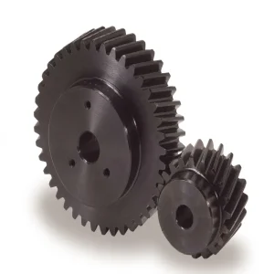
Our standard single-helix helical gear series spans module M0.5 through M6, in both right-hand and left-hand configurations, hobbed and ground variants. Where an application does not require the axial thrust elimination of a double helical gear, the standard helical gear provides a cost-effective parallel-shaft transmission option at the same material and quality grades. Matched helical gear sets — gear and helical pinion gear — are available from the same production run for tightest pair quality.

Gear Rack — Helical Rack and Pinion
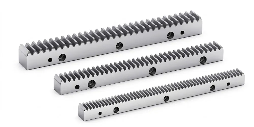
For linear motion axes in aerospace ground support equipment, military vehicle traversing drives, and medical imaging scanner tables, our helical rack and pinion systems provide smooth, accurate linear displacement with the same quiet-running characteristics as their rotary helical gear counterparts. The helical rack tooth geometry is matched to our helical gear pinion series for correct helix angle pairing and consistent backlash control across the full stroke of the linear axis.
نبذة عن منشأة التصنيع الخاصة بنا
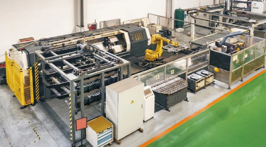
With over ten years of focused expertise in precision mechanical transmission manufacturing, our facility integrates design engineering, CNC gear machining, heat treatment, gear grinding, and coordinate-measuring inspection within a single production environment. Our core manufacturing programme covers agricultural gearboxes, worm gear reducers, planetary gear drives, power take-off shafts, hydraulic cylinders, gears, chains, and motors — produced across a broad range of materials including ductile iron, cast iron, cast steel, precision cast steel, and cast aluminium.
The facility holds ISO 9001:2008 / TS16949 certification — the quality system standard adopted across automotive and aerospace supply chains globally. We design and produce custom gears, sprockets, worm gears, pulleys, shafts, and non-standard mechanical parts to customer-supplied drawings or samples, with full material and process traceability supporting the documentation requirements of aerospace and defence procurement standards.
Our export teams support procurement and engineering customers across Australia, the United Kingdom, Germany, Japan, South Korea, Canada, the Netherlands, and North America more broadly — providing technical data packages, material certifications, and sample evaluation units before batch order commitment. The helical gear factory is equipped for both standard catalogue supply and fully custom made helical gear production across the miniature-to-medium module range.
ورشة عمل



الأسئلة الشائعة
المحرر: PXY