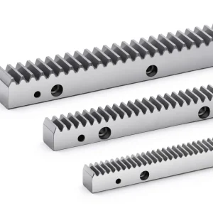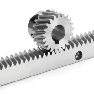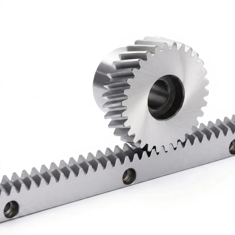
EP-29x29x1000 हेलिकल गियर रैक — M3 प्रेसिजन लीनियर मोशन सॉल्यूशन
The EP-29x29x1000 Helical Gear Rack (Model 552030100) is a high-precision, M3 module rack designed for demanding linear motion and power transmission applications. With helical teeth ground to DIN6 GB5 tolerance, a cross-section of 29×29 mm, and an overall length of 1000 mm, this gear rack delivers consistent, low-noise performance in automation systems, CNC equipment, robotic axes, and heavy industrial machinery. Whether you are engineering a rack and pinion drive for a gantry robot or specifying a linear gear rack for a precision positioning stage, the EP-29x29x1000 is built to meet the load and accuracy requirements of modern production environments worldwide.
EP-29x29x1000 हेलिकल गियर रैक — M3 प्रेसिजन लीनियर मोशन सॉल्यूशन
तकनीकी निर्देश
Every dimension and tolerance listed below has been verified against production drawings for the EP-29x29x1000. The four-side grinding and dedicated tooth-surface grinding process ensures that the rack tooth profile meets DIN6 GB5 precision requirements with tooth-surface hardness of HRC 48–52°, providing reliable performance in high-cycle, heavy-duty applications where a standard spur gear rack would be insufficient.
| पैरामीटर | कीमत | Remarks |
|---|---|---|
| नमूना | 552030100 | Standard helical rack |
| Specification (W×H×L) | 29 × 29 × 1000 mm | Square cross-section, 1000 mm length |
| मॉड्यूल | M3 | Metric module standard |
| दांतों की संख्या | Z = 100 | Full-length engagement |
| Pressure Angle | α = 20° | Standard involute profile |
| Addendum Coefficient | ha = 1 | Standard full-depth tooth |
| Tooth Profile | Helical teeth | Smoother engagement vs. straight rack |
| Helix Angle | 19° 31′ 42″ | Right-hand helix |
| Precision Grade | DIN6 GB5 | High-accuracy class |
| Surface Hardness | HRC 48–52° | Tooth surface high-frequency induction hardening |
| Production Process | Four-side grinding + tooth-surface grinding | Achieves tight parallelism and profile tolerances |
| Mounting Hole Pitch | 50 mm (standard) | Enables easy end-to-end splicing |
How a Helical Gear Rack Works
ए gear rack is, in essence, a gear with an infinite pitch diameter — its teeth are arranged along a straight bar rather than around a circle. When a rotating pinion meshes with the rack, rotational motion is converted into precise linear displacement. The relationship between angular rotation and linear travel is governed directly by the module and the number of pinion teeth, making the rack and pinion gear system one of the most predictable and backlash-controllable linear drive mechanisms available in mechanical engineering.
The distinguishing feature of a helical rack and pinion pairing is the angle at which the teeth are cut. On the EP-29x29x1000, that helix angle is 19° 31′ 42″. This geometry means multiple teeth are always simultaneously engaged, distributing load across a broader contact zone. Compared to a conventional straight gear rack or standard spur gear rack, helical engagement produces significantly lower vibration and noise levels — a critical advantage in automated manufacturing lines where acoustic and dynamic stability directly affect product quality.
High-frequency induction hardening brings the tooth surface to HRC 48–52°, dramatically extending wear life under continuous cyclic loading. The underlying core remains tough and impact-resistant, preventing brittle fracture in shock-load conditions. Four-side precision grinding establishes tight flatness and parallelism of the mounting faces, ensuring that when multiple rack sections are joined end-to-end in a long travel axis, cumulative pitch error remains within the DIN6 GB5 tolerance band. The result is a linear rack and pinion drive that maintains positioning accuracy over the full travel length — essential for applications such as gantry systems, machine tool carriages, and rack and pinion linear slide assemblies.

Five Key Advantages of the EP-29x29x1000 Gear Rack
DIN6 GB5 Precision
Ground to DIN6 GB5 accuracy class, enabling consistent positioning across full rack length — a necessity for precision CNC and robotic axes.
HRC 48–52 Tooth Hardness
High-frequency surface hardening extends wear life substantially compared to through-hardened or untreated racks, reducing maintenance intervals in heavy-duty आवेदन।
Low-Noise Helical Engagement
The 19° 31′ 42″ helix angle ensures smooth tooth contact transition, reducing operational noise and vibration versus a standard straight gear rack.
Four-Side Ground Mounting Faces
All four sides are precision-ground, guaranteeing flat, parallel mounting surfaces for accurate installation and straightforward end-to-end splicing on long travel axes.
Custom Rack Options Available
Beyond the standard 1000 mm length, custom gear rack lengths, modules, and bore configurations are available to meet project-specific design requirements globally.
Material & Manufacturing Process
The EP-29x29x1000 gear rack is manufactured from high-quality alloy structural steel, selected for its balanced combination of strength, toughness, and hardenability. The base material provides sufficient core toughness to absorb dynamic shock loads — particularly relevant in rack and pinion press applications and heavy machine tool drives — while the high-frequency induction hardening process selectively hardens the tooth flanks and tips to HRC 48–52° without embrittling the cross-section.
The four-side grinding operation is carried out on a precision surface grinder after heat treatment, removing any distortion introduced during hardening and establishing tight flatness tolerances on all mounting faces. Tooth-surface grinding then brings the helical tooth flanks to the DIN6 GB5 profile accuracy, controlling pitch error, tooth-to-tooth variation, and total accumulated pitch error within tightly defined limits.
The combination of alloy steel substrate, surface hardening, and ground tooth geometry results in a linear gear rack that performs reliably in environments where lubrication may be intermittent, loads are heavy, and cycle counts are high. Anti-rust treatment is applied as a standard protective measure prior to packaging and shipping, maintaining surface integrity during transit to customers in Australia, the UK, the Netherlands, North America, South Korea, and other global markets.
अनुप्रयोग परिदृश्य
The EP-29x29x1000 helical gear rack finds use in a wide range of industrial sectors. Its precision ground teeth and high surface hardness make it equally at home in light-duty automation and in heavy machine tools. The following application areas represent typical deployments of M3 module helical racks worldwide — from European manufacturing plants to Asia-Pacific processing facilities.
🛠 CNC Machine Tools
Machining centres, gantry mills, and boring machines rely on gears rack and pinion drives for rapid axis travel combined with precise positioning. The helical tooth geometry minimises chatter transmitted to the cutting tool.
🤖 Industrial Robotics & Gantry Systems
Gantry robots and Cartesian handling systems depend on rack and pinion linear slide assemblies for high-speed, repeatable part transfer. The EP rack's DIN6 accuracy ensures minimal cumulative travel error over long strokes.
🚗 Automated Storage & Retrieval
AS/RS stacker cranes and shuttle systems use duty gear rack drives to move storage and retrieval heads at high speed. The hardened tooth surface withstands millions of engagement cycles without significant wear.
🔧 Laser & Plasma Cutting Machines
High-speed laser cutting tables use precision helical rack and servo pinion combinations to move cutting heads accurately at velocities exceeding 100 m/min. The smooth engagement of helical teeth is critical here.
🏭 Press & Stamping Equipment
In rack and pinion press configurations and die-transfer mechanisms, the rack must handle significant thrust loads. The alloy steel core and hardened tooth surface of this gear rack are well-suited to these cyclic impact conditions.
संबंधित उत्पाद और सिस्टम अनुकूलता
We manufacture the complete gear rack and pinion system — not just the rack. Sourcing the rack and its mating components from a single production facility eliminates inter-supplier tolerance stack-up and simplifies qualification. Below are two product families that are frequently specified alongside the EP-29x29x1000.
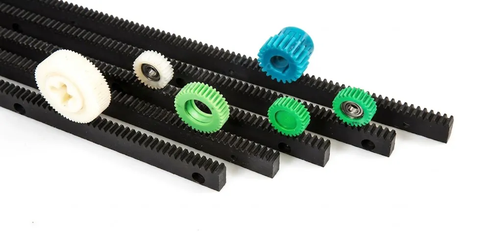
प्लास्टिक गियर रैक
For applications where weight reduction, corrosion resistance, or low-noise operation in dry environments is the priority, our plastic gear rack series offers a direct profile-compatible alternative. Available in multiple modules including M3, these racks pair directly with standard steel pinions and are widely used in medical, food-processing, and light automation equipment across global markets.
Helical Gear (Pinion)
The EP-29x29x1000 is specifically designed to mesh with a matching M3 helical gear pinion. Our full series of helical gears covers modules from M1 through M10, in straight-bore and keyed-bore configurations, manufactured to the same DIN precision grades as the rack. Specifying both from the same production source guarantees matched helix angles and eliminates lead-mismatch errors in the rack pinion gear mesh.
About Us — 10+ Years of Mechanical Transmission Expertise
With more than a decade of focused experience in mechanical power transmission, our production facility operates under ISO 9001:2015 certification, applying a quality management framework that spans incoming material inspection, in-process dimensional control, and final performance verification before shipment.
Our manufacturing scope covers a broad portfolio: agricultural gearboxes, worm gear reducers, planetary gear drives, power take-off (PTO) shafts, hydraulic cylinders, gears, roller chains, and electric motors. We also design and produce a wide spectrum of industrial and agricultural gearbox assemblies in materials including ductile iron, cast iron, cast steel, precision investment cast steel, and cast aluminium — along with sprockets, worm gears, pulleys, worms, shafts, and both standard and engineered-to-order mechanical components.
अक्सर पूछे जाने वाले प्रश्नों
संपादक: पीएक्सवाई