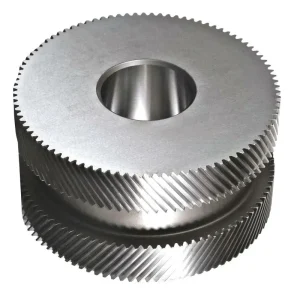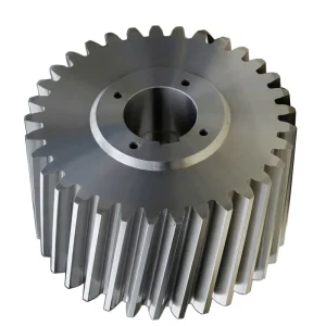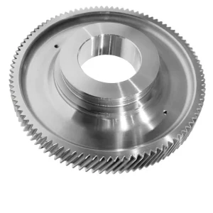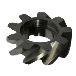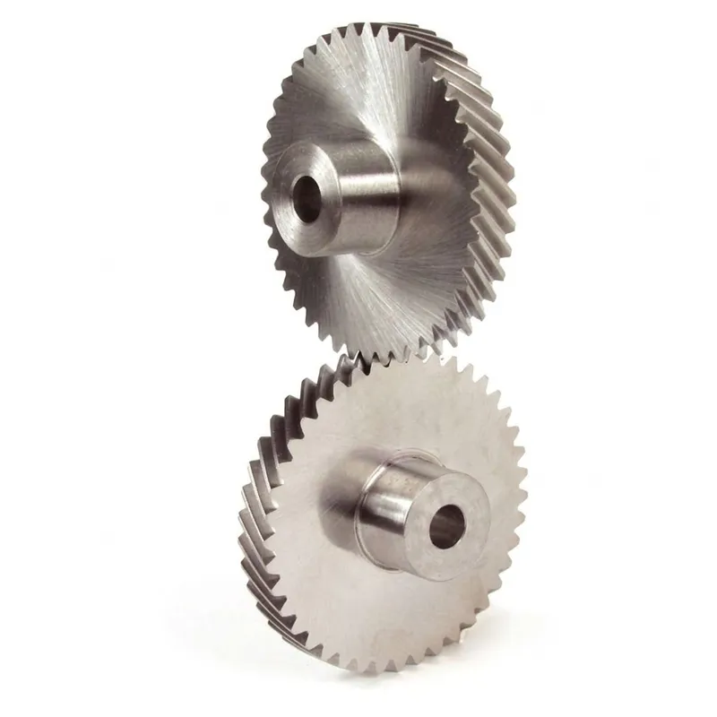
EP-Crossed Helical Gear (Screw Gear)
The EP-Crossed Helical Gear (Screw Gear) is a precision transmission component designed for non-parallel, non-intersecting shaft applications. Available in modules from M1 to M12, these gears are manufactured from versatile materials including Brass, C45 Steel, Stainless Steel, Copper, POM, and Aluminum to suit diverse load and environmental requirements. They achieve high precision standards of DIN6 to DIN9 with tight tolerances ranging from 0.001mm to 0.1mm. Surface treatments such as Zinc-plating, Anodization, and Passivation enhance durability, while tooth treatments include hardening, milling, or grinding for optimal performance. Compliant with ISO, DIN, ANSI, and JIS standards, these gears are widely used in automatic control machines, semiconductor equipment, medical devices, and solar energy systems. With a sample lead time of 20 business days and bulk production in 25 days, EP offers reliable solutions for complex mechanical drives requiring smooth operation at right angles.
Precision Motion Control / Crossed-Axis Gear Transmission
EP-Crossed Helical Gear (Screw Gear)
A precision-manufactured helical gear engineered for non-parallel, non-intersecting shaft arrangements — delivering smooth, quiet motion transmission across a broad range of modules, materials, and surface treatments for industrial automation, medical equipment, semiconductor machinery, and high-speed rail applications worldwide.
Materials: Brass / C45 / SS / POM / Alloy
Precision: DIN6–DIN9
Standards: ISO / DIN / ANSI / JIS / BS
Tolerance: 0.001–0.1 mm
ISO 9001:2015 Certified
Technical Specification Parameters
The table below presents the full specification range for the EP-Crossed Гвинтова шестерня (Screw Gear) series. Because this helical gear family is produced to order across a wide range of modules, materials, and surface treatments, most parameters are specified per project. The ranges shown represent the standard manufacturing envelope; requirements outside these ranges are assessed on an individual basis.
| Параметр | EP-Crossed Helical Gear (Screw Gear) |
|---|---|
| Model Number | M1, M1.5, M2, M2.5, M3, M4, M5, M8, M12 and etc. |
| Матеріал | Brass, C45 steel, Stainless steel, Copper, POM, Aluminum, Alloy, and so on |
| Обробка поверхні | Zinc-plated, Nickel plated, Passivation, Oxidation, Anodization, Geomet, Dacromet, Black Oxide, Phosphatizing, Powder Coating, and Electrophoresis |
| Стандартний | ISO, DIN, ANSI, JIS, BS and Non-standard |
| Precision Grade | DIN6, DIN7, DIN8, DIN9 |
| Teeth Treatment | Hardened, Milled, or Ground |
| Tolerance | 0.001 mm – 0.01 mm – 0.1 mm |
| Finish Options | Shot/sandblast, heat treatment, annealing, tempering, polishing, anodizing, zinc-plated |
| Packing | Plastic bag + Cartons or Wooden Packing |
| Payment Terms | T/T, L/C |
| Production Lead Time | Sample: 20 business days; Bulk: 25 days |
| Тип шестерні | Crossed Helical Gear (Screw Gear) |
| Shaft Arrangement | Non-parallel, non-intersecting (typical crossing angle: 90°; other angles available) |
| Quality Management | ISO 9001:2015 |
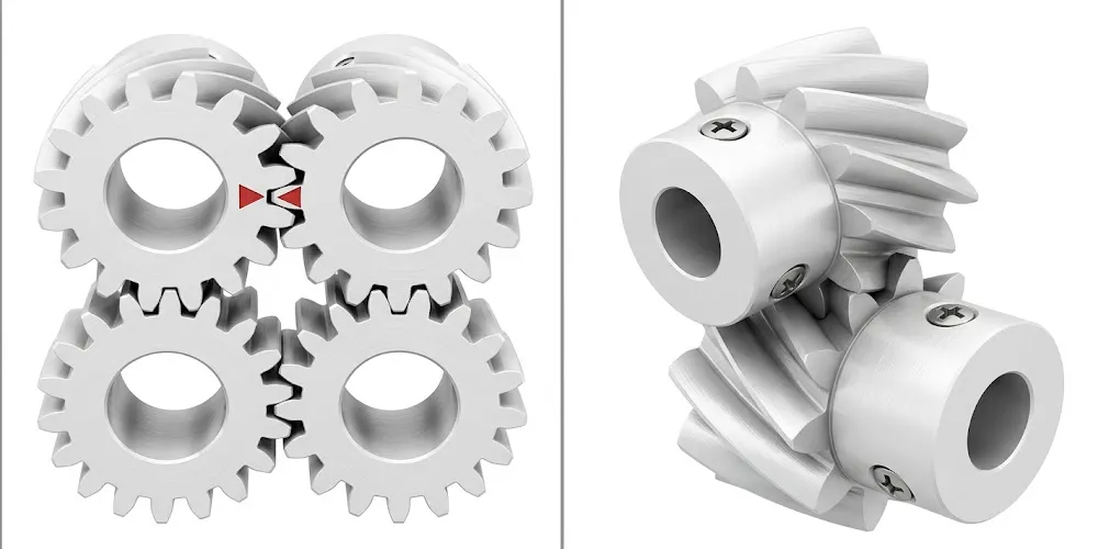
What Is a Crossed Helical Gear?
A crossed helical gear — also known as a screw gear — is a specific configuration of the standard helical gear form, adapted to transmit motion between shafts that are neither parallel nor intersecting. While a conventional helical gear pair operates with shafts running in the same plane and at zero crossing angle, crossed helical gear pairs are deliberately assembled with a shaft crossing angle, commonly 90°, although other angles are achievable through matching helix angle combinations. This crossed-axis arrangement makes the screw gear fundamentally different in its contact mechanics from any other helical gear type: rather than line contact across the tooth face width, the contact between crossed helical gear teeth is theoretically a point. In well-lubricated, lightly loaded applications, this point contact is entirely adequate; it is what enables the crossed helical gear to transmit motion between shafts at arbitrary crossing angles without the complex geometry of bevel or hypoid gears.
The EP-Crossed Гвинтова шестерня series covers modules from M1 through M12 and beyond, in a material range spanning brass, C45 steel, stainless steel, copper, POM, aluminium, and alloys — reflecting the equally broad application range of this helical gear type. A brass crossed helical gear, for instance, suits instrument applications where weight and non-magnetic properties matter; a C45 steel version suits general industrial machinery; a stainless steel crossed helical gear suits food processing and medical environments where corrosion resistance is required; and a POM (acetal) version suits automation equipment where quiet, lubrication-free operation at light loads is the priority. This flexibility of material selection — within a consistent helical gear design framework — is one of the defining commercial strengths of the crossed helical gear product family.
Precision grades from DIN6 to DIN9 are available, with tolerance bands from 0.001 mm for the finest instrument-grade applications to 0.1 mm for general-purpose industrial uses. Tooth treatments — hardened, milled, or ground — and an extensive range of surface finishing options including zinc-plating, nickel plating, passivation, anodization, Geomet, Dacromet, black oxide, phosphatizing, powder coating, and electrophoresis, all contribute to making this the most configurable product in the helical gear range.
Five Key Advantages of the Crossed Helical Gear
① Crossed-Axis Motion — No Bevel or Worm Gear Required
The most distinctive capability of the crossed helical gear is its ability to connect non-parallel, non-intersecting shafts using nothing more complex than a pair of standard cylindrical helical gear blanks cut with appropriately selected helix angles. Where a designer might otherwise need a bevel gear pair (limited to intersecting shafts) or a worm gear set (one direction of drive only), a crossed helical gear pair can handle shaft angles from a few degrees up to 90° or beyond in either direction. The manufacturing equipment used is the same as for conventional helical gear machining — hobbing and grinding — so there is no tooling premium for the crossed configuration. This simplicity makes the crossed helical gear the pragmatic choice for instrument mechanisms, light automation drives, and any application where shaft layout constraints make bevel or worm gear geometry inconvenient.
② Exceptionally Wide Material Range
Few helical gear products are offered across as broad a material portfolio as the crossed helical gear series. Brass delivers excellent machinability, dimensional stability, and corrosion resistance for instrument and medical applications. C45 steel provides a reliable, cost-effective general-purpose substrate for industrial machinery where moderate load capacity and straightforward heat treatment are appropriate. Stainless steel helical gears — particularly 304 and 316 grades — resist chemical attack and moisture in food processing, pharmaceutical, and laboratory environments. POM (polyoxymethylene) produces a helical gear that runs quietly without external lubrication, making it suitable for office automation, consumer electronics, and cleanroom systems. Copper and aluminium variants address specialist requirements around electrical conductivity and weight. This breadth of material availability from a single helical gear supplier streamlines procurement and ensures application-specific optimisation rather than compromise.
③ Multi-Standard Compliance — ISO, DIN, ANSI, JIS, BS
For buyers sourcing helical gear components into regulated industries or for OEM integration with equipment designed to specific national standards, the EP-Crossed Гвинтова шестерня series is manufactured and inspected against ISO, DIN, ANSI, JIS, and BS standards — with non-standard configurations available on request. This multi-standard flexibility eliminates the need to qualify different suppliers for different regional markets. A medical equipment manufacturer in Japan, a semiconductor tool builder in the United States, a machine tool producer in Germany, and a solar energy systems integrator in Australia can all source from the same product family with the documentation applicable to their respective regulatory environment. Few helical gear manufacturers offer this combination of standard breadth and dimensional range within a single product line.
④ Comprehensive Surface Treatment Options
The surface treatment selected for a helical gear can be as consequential as the base material, particularly when operating environment durability, friction coefficient, or appearance standards are specified by the end customer. The crossed helical gear series is available with zinc plating, nickel plating, passivation, oxidation, anodization, Geomet coating, Dacromet coating, black oxide, phosphatizing, powder coating, and electrophoresis — a treatment portfolio that covers corrosion protection, decorative finish, friction reduction, and wear resistance requirements across virtually the full spectrum of light-duty industrial applications. Geomet and Dacromet coatings in particular are specified increasingly in European automotive and aerospace supply chains for their chromate-free corrosion protection, and the availability of these coatings on a precision helical gear represents a meaningful product differentiation for buyers in those sectors.
⑤ Fast Lead Times with Sample Programme
For design engineers evaluating the crossed helical gear at prototype stage, the availability of samples within 20 business days — combined with bulk production in 25 days — is a practical advantage that shortens development cycles. Many helical gear manufacturers require tooling runs or minimum quantities before samples can be supplied, creating bottlenecks in the early stages of mechanism design. The sample programme for the crossed helical gear series allows engineers to confirm fit, function, and tooth mesh quality before committing to a production order, reducing the risk of expensive late-stage design changes. Payment terms include T/T and L/C, and packing defaults to plastic bag and carton or wooden case depending on order volume and destination — standard international shipping compliance without additional negotiation.
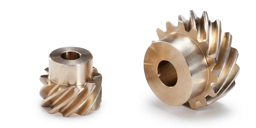
How a Crossed Helical Gear Works
To understand how a crossed helical gear transmits motion, it helps to begin with the geometry of a single helical gear tooth. In a conventional parallel-shaft helical gear pair, both gears share the same normal module and operate with helix angles of equal magnitude but opposite hand. The mating teeth engage in line contact that sweeps across the full face width during the mesh cycle. A crossed helical gear pair uses a fundamentally different arrangement: the two gears can have the same or different helix angles, and both can be the same hand (both right-hand or both left-hand) or opposite hands, depending on the required shaft crossing angle. For a 90° shaft angle — the most common crossed helical gear application — both gears are typically cut with the same helix angle (e.g., both at 45°) and the same hand.
Because the shafts cross rather than being parallel, the contact between mating helical gear teeth is point contact rather than line contact. This geometric reality has two practical consequences. First, the load-carrying capacity of a crossed helical gear pair is substantially lower than a comparable parallel-shaft helical gear set of the same module and face width, since load is concentrated at a point rather than distributed along a line. Second, and more critically from a wear standpoint, the tooth contact involves significant sliding rather than predominantly rolling motion. Unlike parallel-shaft helical gear pairs where the sliding component at the contact zone is relatively small, crossed helical gear pairs experience combined rolling and sliding throughout the tooth mesh cycle. This sliding is what generates the frictional heat and wear that limits the crossed helical gear to light-duty, relatively slow-to-moderate speed applications unless premium lubricants and surface finishes are employed.
The relationship between helix angle selection and the achievable shaft crossing angle gives the crossed helical gear its design flexibility. If the helix angle of Gear 1 is α₁ and the helix angle of Gear 2 is α₂, and both are the same hand, the shaft crossing angle Σ = α₁ + α₂. If they are opposite hands, Σ = α₁ − α₂. This simple algebraic relationship means an engineer can target any required shaft crossing angle by selecting appropriate helix angle combinations — a level of geometric flexibility not available from any other helical gear type. Combined with the ability to run the crossed helical gear pair with a speed ratio independent of the tooth count ratio when helix angles differ, this makes the crossed helical gear a compact, versatile motion element for complex mechanism designs.
Lubrication of a crossed helical gear pair is important precisely because of the high sliding ratio at the tooth contact. For metal crossed helical gear pairs — brass, steel, or stainless steel — an appropriate gear oil or grease is required to prevent adhesive wear at the contact point. POM and similar polymer crossed helical gear variants are self-lubricating to a degree, tolerating dry operation at light loads and moderate speeds, which accounts for their popularity in office automation and consumer electronics applications where periodic relubrication would be impractical.
Material Selection & Quality Standards
Selecting the correct helical gear material for a crossed helical gear application requires considering not only the transmitted load and operating speed but also the environment, the mating gear material, and the lubrication condition. Because crossed helical gear pairs involve significant tooth sliding, the tribological compatibility of the mating materials is particularly important: metal-on-metal pairs require good lubrication; dissimilar metal pairs (e.g., brass wheel against steel pinion) can reduce adhesive wear risk; polymer-on-metal pairs enable dry operation at the cost of reduced load capacity.
- Brass — Free-machining brass (commonly CuZn39Pb3 or equivalent) is the most widely used material for small-module crossed helical gear sets in instruments, office machines, and light automation. Its machinability enables tight dimensional tolerances at competitive cost, and the material's inherent lubricity reduces adhesive wear in lightly lubricated or unlubricated contacts against a steel helical gear pinion.
- C45 Steel (Medium Carbon Steel) — The general-purpose metal choice for crossed helical gear sets in industrial machinery, conveyor drives, and general automation. Can be through-hardened to improve surface hardness and wear resistance. Steel helical gear pairs at this specification suit moderate loads and speeds where a full polymer solution would be insufficient.
- Stainless Steel — 304 and 316 grades resist moisture, acids, and alkaline cleaning agents, making stainless steel helical gears the specification of choice for food processing equipment, pharmaceutical mixing drives, laboratory instruments, and marine auxiliary machinery. Hardness is lower than alloy steel, so applied loads must be derated, but the corrosion resistance is unmatched by any other metallic option in the crossed helical gear range.
- POM (Polyoxymethylene / Acetal) — Offers a unique combination of dimensional stability, low friction coefficient, and self-lubricating behaviour that suits dry-running crossed helical gear applications in office automation, consumer electronics, and cleanroom environments. POM absorbs minimal moisture, maintaining dimensional accuracy in humid conditions, and its noise signature is lower than any metal helical gear at equivalent pitch-line velocities.
- Copper, Aluminium, and Alloy variants — Copper crossed helical gear sets suit applications where electrical conductivity, thermal conductivity, or specific bearing characteristics with mating steel gears are priorities. Aluminium variants address weight-critical designs in aerospace, portable instruments, and solar tracking drives. Custom alloy specifications are accommodated on a project basis.
Every crossed helical gear in this series is produced under ISO 9001:2015 quality management. Dimensional verification covers tooth profile, helix angle, pitch, and runout to the applicable DIN precision grade, with full material certification available for regulated industries. The tolerance range of 0.001 mm–0.1 mm spans from instrument precision to general industrial standards within the same product family, eliminating the need to source from separate helical gear suppliers for different precision tiers.
Application Sectors
The crossed helical gear is a specialist motion element whose crossed-axis capability, multi-material range, and compact geometry make it the preferred choice in a specific set of applications where other helical gear types or bevel gear pairs would be geometrically or economically inconvenient. The sectors below represent the primary markets served globally by this product.
Industrial Automation & Automatic Control Systems
Industrial automation equipment — including robotic arms, pick-and-place systems, conveyor indexing mechanisms, and automated assembly lines — frequently requires motion transmission between shafts that are laid out at angles dictated by machine geometry rather than gear geometry. The crossed helical gear accommodates these layout constraints without requiring the designer to reorient motors or shafts to achieve parallel alignment. In European and North American automated manufacturing plants, crossed helical gear sets in small modules (M1–M3) are routinely used for position feedback drives, valve actuators, and axis indexing mechanisms. The availability of precision DIN6 and DIN7 grades ensures that backlash levels are compatible with closed-loop position control requirements.
Semiconductor Manufacturing Equipment
Semiconductor fabrication equipment imposes the most stringent possible requirements on mechanical components: dimensional precision measured in micrometres, particle generation near zero, resistance to aggressive cleaning solvents, and compatibility with vacuum environments in some cases. The crossed helical gear is used in wafer handling stages, lithography mask positioning systems, and metrology equipment drives where compact size, crossed-axis transmission, and material cleanliness are simultaneously required. Stainless steel and POM crossed helical gear variants are particularly relevant here — the former for vacuum-compatible, cleanable components, the latter for dry-running, particle-minimising applications in less demanding process environments. Buyers in Taiwan, South Korea, Japan, and the Netherlands specify these precision helical gear components for semiconductor tool integration.
Medical Equipment & Laboratory Instruments
Medical devices — from surgical robots to diagnostic imaging drives and infusion pump mechanisms — rely on small, precise, clean helical gear components to transmit motion between non-parallel shafts in highly constrained enclosures. Stainless steel crossed helical gear sets suit sterilisable environments; brass versions suit general medical instrument applications where biocompatibility and machinability are the governing factors. The multi-standard compliance of this helical gear series — covering ISO, DIN, ANSI, JIS, and BS — simplifies regulatory submissions for medical device manufacturers in the EU (MDR), the US (FDA 510k), and Japan (PMDA), who all require documented component traceability and standards compliance as part of device qualification.
Solar Energy Tracking Systems
Single-axis and dual-axis solar tracker drives require compact, reliable gear stages that convert slow motor rotation into precise panel angle adjustment. Crossed helical gear pairs are used in the angular drive stages of many tracker designs, particularly where motor and panel shaft axes must be arranged at 90° due to the mechanical layout of the tracker frame. Aluminium crossed helical gear variants reduce weight in rooftop and floating solar tracker applications; stainless steel variants withstand the corrosive outdoor environments of coastal solar farms in Australia, the Middle East, and Southeast Asia. The long service life expected of solar tracking equipment — typically 20–25 years — drives demand for the higher-precision DIN6 and DIN7 crossed helical gear grades that minimise cumulative angular positioning error over time.
High-Speed Rail & Aviation Transport Equipment
In aviation and high-speed rail auxiliary systems, crossed helical gear sets appear in actuation mechanisms, instrumentation drives, and ancillary control systems where crossed-axis transmission is required in tight, weight-critical packaging. The demands in these sectors — precision, reliability, and compliance with aerospace or rail authority standards — push specification to DIN6 precision in hardened or ground tooth form, with surface treatments (Dacromet or Geomet) that resist the combined corrosion and vibration environment of transport applications. Buyers in Germany, France, and Japan, where rail and aerospace manufacturing is concentrated, routinely specify crossed helical gear components to JIS or DIN standards as a baseline requirement for system integration.
General Industrial Machinery & Machine Tools
Beyond the specialist sectors above, the crossed helical gear is a standard motion element in general industrial machinery wherever crossed-axis drive is needed. Parking system drives — an application that has grown substantially across East Asia and Europe as multi-storey automated parking expands — use crossed helical gear sets in the pallet transfer and elevation mechanisms. Machine tool accessories, general-purpose gear drives, and conveyor divert mechanisms all represent volume applications for the M2–M8 range of the crossed helical gear series. The standard DIN8/DIN9 grades at C45 steel specification cover the majority of these general industrial applications at competitive lead times and economical cost.
Crossed Helical Gear vs Worm Gear — Choosing the Right Solution
The crossed helical gear and the worm gear both transmit motion between non-parallel, non-intersecting shafts, and at first glance their application spaces appear to overlap. In practice, the two gear types occupy quite distinct positions in the designer's toolbox, and understanding the difference prevents costly misspecification. A worm gear and helical gear comparison reveals that worm gear drives achieve high reduction ratios in a single stage — often 10:1 to 60:1 — and are inherently self-locking under many load conditions. This self-locking property is either an asset (preventing back-driving in lifting equipment) or a liability (preventing regenerative braking in servo drives). The crossed helical gear, by contrast, is typically used at relatively low reduction ratios, is not self-locking, and can be driven from either the input or output side. It is not a replacement for a worm gear reducer; it is a complementary motion element suited to different application requirements.
| Characteristic | Crossed Helical Gear | Worm Gear |
|---|---|---|
| Contact Type | Point contact | Line contact (wrapped) |
| Load Capacity | Light to moderate | Moderate to high |
| Коефіцієнт зменшення | Low (typically 1:1 to 5:1) | High (10:1 to 60:1 per stage) |
| Самоблокування | Ні | Often yes |
| Back-Driveability | Так | Typically no |
| Manufacturing Tool | Standard hobbing / grinding | Worm-specific equipment |
| Material Range | Very wide (brass to POM to SS) | Typically steel worm / bronze wheel |
Related Products & One-Stop Supply
A crossed helical gear often operates alongside other gear forms and linear motion components within the same drive train. Sourcing all matched elements from one supplier eliminates dimensional incompatibilities and simplifies quality documentation — particularly important in regulated industries such as medical devices and semiconductor equipment. The two product families below are most commonly specified alongside the crossed helical gear for complete drive system procurement.
Helical Gear (Full Series)
The broader helical gear range complements the crossed configuration with standard parallel-shaft helical gear sets in modules matching the crossed helical gear series — M1 through M12 and beyond. When a drive system requires a parallel-shaft reduction stage feeding into a crossed-axis transmission stage, both elements can be sourced as a matched set with compatible module and tooth profile specifications. The full helical gearset portfolio spans small-module precision gears for servo and instrument drives through to large-module industrial gears for machine tool and conveyor applications. One-source procurement for the entire helical gear content of a gearbox or mechanism simplifies assembly and quality verification, and reduces the lead time risk associated with multi-vendor sourcing.

Зубчаста рейка
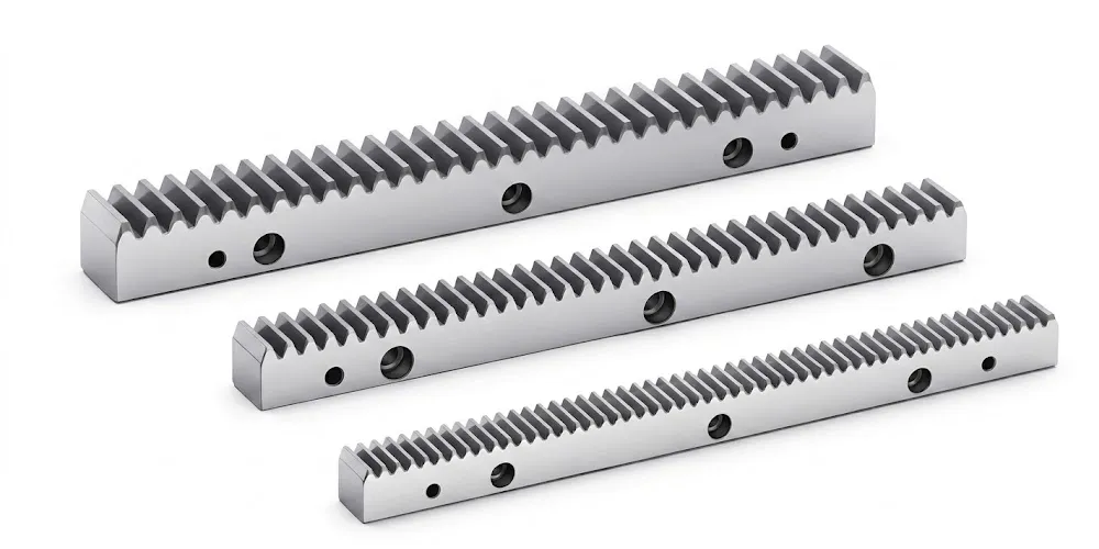
For applications requiring linear motion output from a rotary drive — CNC axes, automated parking lifts, solar tracker linear stages, and gantry transport systems — the gear rack range provides the linear element to work alongside helical pinion gears. Rack modules are matched to the helical gear module series, ensuring pitch compatibility without profile modification. The helical rack and pinion arrangement extends the same smooth, low-noise engagement characteristic of the helical tooth form into linear motion applications. Available in straight and helical rack forms in standard lengths for modular jointing, the gear rack rounds out the complete helical gear and rack system supply for multi-axis machine and automation procurement.
Про виробничий об'єкт
With over a decade of focused experience in precision mechanical transmission engineering, our manufacturing facility produces a comprehensive range of drive components for industrial, agricultural, and specialist technical markets worldwide. The product scope includes agricultural gearboxes, worm gear reducers, planetary gear drives, power take-off shafts, hydraulic cylinders, gears, chains, and motors — giving procurement teams a technically capable, single-source option for complex multi-component drive system builds.
The facility operates under ISO 9001:2015 certification, with quality management applied systematically from raw material acceptance through to final dimensional verification and dispatch. We design and manufacture industrial and agricultural gearboxes and assemblies in ductile iron, cast iron, cast steel, precision cast steel, and cast aluminium, as well as standard and non-standard mechanical parts including gears, sprockets, worm gears, pulleys, worms, and shafts — all in-house, under the same quality system. This vertical integration means material traceability, dimensional control, and surface treatment quality are all managed within one facility rather than distributed across a network of subcontractors.
The crossed helical gear programme sits within this broader manufacturing base and benefits from the precision CNC machining, multi-standard measurement capability, and surface treatment expertise that support the wider gear and transmission product range. Buyers in Europe, North America, Japan, South Korea, Australia, and Southeast Asia source crossed helical gear components from this facility for both prototype and production programmes. We are a factory — direct engineering engagement, not a trading intermediary — and every technical query on helical gear design, material selection, or surface treatment is answered by the people who produce the product.
Часті запитання
The questions below address the most common technical and sourcing queries from design engineers and procurement teams evaluating crossed helical gear components for automation, medical, and industrial applications globally.
Редактор: PXY