
Offshore Drilling · Drive Technology
How Single-Speed Gear Reducers Are Used for Precise Depth Control in Offshore Drilling Winch and Pulley Block Drives
A technical reference covering worm gear reducer construction, load holding characteristics, material engineering, and product selection for offshore and onshore drilling winch and crown block drive applications worldwide.
Depth control in offshore drilling operations is a precision-critical function. Whether positioning a drill string at a target formation depth in the North Sea, managing the controlled descent of casing in a Gulf of Mexico deepwater well, or operating wireline and logging tools in Middle Eastern onshore exploration wells, the drive system that governs winch and crown block movement must deliver accurate, repeatable speed and load control under widely varying tension conditions. A small positioning error at the surface translates to an amplified depth error at the bit or tool — with consequences that range from inefficient drilling to formation damage or equipment loss in the hole.
The single speed reducer based on the worm gear principle occupies a specific and well-established role within the broader drilling winch drive architecture. While the main drawworks on a large offshore rig uses multi-stage planetary or helical gear systems capable of handling hundreds of kilonewtons of hook load, a range of auxiliary winches, tugger hoists, wireline units, logging tool conveyance systems, and pulley block adjustment mechanisms use smaller worm gear speed reducers that provide the torque multiplication, speed precision, and inherent load-holding capability that these secondary drives require. For these applications, the single stage right-angle worm-gear speed reducer is the standard engineering solution.
This article examines how the mechanical architecture and material system of the WP-series single speed reducer addresses the specific demands of drilling winch and pulley block service, covers the role of self-locking behaviour in depth-hold applications, and provides product selection guidance for engineers and procurement specialists evaluating single reduction worm reducer options for offshore and onshore drilling support equipment globally.

Manufacturing Structure of the WP-Series Single Speed Reducer for Drilling Service
The WP-series single speed reducer is built from a single-piece integrally cast housing that encloses both the worm shaft and the output shaft within a right-angle arrangement. Machining the bearing bores for both shafts in a single fixture operation — which the integral casting makes possible — ensures bore-to-bore perpendicularity and concentricity that a split-housing design cannot match without careful realignment at every reassembly. For offshore drilling support equipment, where the reducer is installed on a winch frame or derrick structure that experiences wave-induced motion and drilling vibration, the dimensional stability of an integrally cast housing maintains gear mesh alignment and bearing positioning through conditions that would gradually distort a bolted split housing over a service cycle.
The worm shaft is straddle-mounted — supported by rolling element bearings at both shaft ends — distributing radial and thrust loads symmetrically across two bearing positions. This matters for winch drum drives where the wire rope fleet angle and drum load impose a combination of radial and moment loads on the output shaft. Under the cyclic loading of a wireline winch pulling and releasing tension repeatedly during logging runs, the straddle-mounted configuration prevents shaft deflection that would otherwise shift the worm-wheel contact band across the tooth face width, generating uneven wear and premature fatigue failure at the contact surface edges.
Standard center distances across the WP series range from 40 to 250 mm, with frame sizes at 40, 50, 60, 70, 80, 100, 120, 135, 155, 175, 200, and 250 mm. The output torque and shaft diameter scale proportionally with center distance, covering winch drum drive requirements from small wireline units handling a few kilonewtons of line tension through to auxiliary tugger hoists on platform cranes rated at several tonnes. The housing provides machined flat surfaces at multiple positions for foot-mount, flange-mount, and shaft-mount configurations from the same casting family, accommodating the varied structural interfaces encountered across different winch and hoist designs.
Material System: Offshore Environmental Resistance and Mechanical Durability
The housing is cast in grey cast iron, which provides adequate structural strength for the torsional and bending loads of winch service combined with a damping capacity that attenuates the shock pulses transmitted from the wire rope when sudden load changes occur — during tool string jarring operations, for example, or when a stuck drill pipe is freed suddenly. The external surface of the housing requires robust protection in the offshore environment. Salt-laden air, water spray on the drill deck and moonpool area, and the hydrogen sulfide atmosphere present in sour gas operations all aggressively attack unpainted cast iron. Epoxy powder coat over zinc phosphate primer is the minimum specification for open-deck offshore installations. In particularly corrosive zones — the splash zone of a jackup rig leg, for example, or locations near H₂S vent stacks on gas processing platforms — two-part epoxy paint with additional thickness is appropriate.
The worm shaft is alloy steel case-hardened to 45–55 HRC at the tooth flanks, with the tooth profile ground post-hardening to remove heat treatment distortion and achieve a controlled contact geometry. The smooth ground flanks generate less friction heat under the cyclic loading of a winch application — important in a service where the reducer may be cycling rapidly during casing running operations, producing heat faster than convection from the housing surface can dissipate it. The worm wheel is phosphor bronze or tin bronze, the material choice that defines worm gear tribology: retaining lubricant film at the mesh contact, accommodating the sliding motion of worm mesh geometry with low friction coefficients against the hardened steel worm, and sacrificing preferentially on overload to protect the more expensive worm shaft.
Output and input shafts are medium-carbon or alloy steel, dimensioned for rated torque and machined with keyways or spline forms that match standard coupling bores. For offshore winch applications where the output shaft drives a winch drum through a chain or coupling, the shaft and keyway dimensions must be confirmed against the winch drum hub bore specification during the mechanical package design phase to avoid field modification on the drill deck.
Featured Product: EP-WPDKA Single Speed Reducer — 5 to 350 kg Shaft Load, Motor-Flange Hollow-Bore Configuration
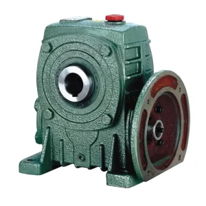
The EP-WPDKA combines an integral motor mounting flange with a hollow output shaft bore — the WPDKA designation indicating the double-flange (motor + hollow output) variant of the WP series. For offshore drilling winch and hoist applications, this configuration offers two installation advantages that matter in the confined mechanical spaces of a derrick substructure or moon pool equipment bay. The direct motor flange attachment eliminates the coupling element between motor and reducer, removing one mechanical interface and its associated alignment requirement. The hollow output bore mounts directly on the winch drum shaft, eliminating the output coupling and its alignment procedure as well. The result is a compact, two-flange motor-to-drum drive package that takes up less axial length than any solid-shaft arrangement and requires fewer precision alignment checks during installation and after drydock maintenance.
The shaft load rating of 5 to 350 kg accommodates the structural weight of motor and reducer hanging from the winch drum shaft in a vertical installation — common in overhead wireline units and monorail hoists on offshore platforms. The reduction ratio range of 10:1 through 60:1 covers the drum speed requirements of wireline, tugger hoist, and auxiliary crown block adjustment applications.
| Parameter | Специфікація |
|---|---|
| Shaft Load Rating | 5 – 350 kg |
| Output Configuration | Hollow bore, shaft-mount (motor-flange integrated) |
| Reduction Ratios Available | 10:1 / 15:1 / 20:1 / 25:1 / 30:1 / 40:1 / 50:1 / 60:1 |
| Housing Material | Grey cast iron (epoxy coating for offshore service) |
| Worm Wheel Material | Phosphor bronze / tin bronze |
| Worm Shaft Material | Case-hardened alloy steel, ground tooth flanks (45–55 HRC) |
| Motor Interface | Integral motor flange, IEC/NEMA compatible |
| Center Distance Range | 40 – 250 mm (12 standard frame sizes) |
| Self-Locking Property | At ratios above ~20:1, drive resists back-driving under static load |
| Primary Application | Wireline winch, tugger hoist, crown block adjustment, logging tool conveyance |
Self-Locking Behaviour and Depth-Hold Capability in Drilling Winch Service
The self-locking property of the worm drive is the feature that most directly addresses the depth control requirement of drilling winch and logging tool conveyance applications. At worm lead angles below approximately 5 to 6 degrees — which correspond to reduction ratios above roughly 20:1 — the friction at the worm-wheel tooth contact is sufficient to prevent the output shaft load from back-driving the worm when the motor is de-energised. In a wireline winch context, this means the tool string weight suspended in the hole does not cause the winch drum to unwind when the motor is stopped — the tool remains at depth without the winch motor energised and without a separate mechanical brake providing continuous holding force.
For logging tool conveyance in exploration wells across the North Sea, offshore West Africa, or deepwater Gulf of Mexico where tool depth tracking accuracy affects formation evaluation quality, the ability to hold position during data acquisition pauses without relying on an energised motor is operationally valuable. It reduces power consumption during stationary logging, removes the risk of creep movement from a fading brake, and simplifies the control system by reducing the number of active hold mechanisms that must be maintained simultaneously. The worm gear speed reducer’s self-locking at the chosen reduction ratio acts as a passive mechanical interlock that holds depth position regardless of electrical supply condition.
Engineers specifying a single speed reducer for depth-hold applications should verify self-locking under the specific combination of reduction ratio, oil type, and operating temperature intended for the installation. Self-locking is a static property that depends on the coefficient of friction at the tooth contact — which changes with lubricant viscosity, surface temperature, and the degree of boundary versus hydrodynamic lubrication at the worm mesh. A drive that self-locks reliably at 15°C sump temperature may show marginally reduced holding tendency at 70°C when synthetic oil reduces the friction coefficient. This verification should be part of the functional testing protocol before a wireline or logging winch enters offshore service.

Winch and Pulley Block Drive Architecture for Offshore Drilling Operations
Offshore drilling rig winch systems cover a wide functional range. The main drawworks, which handles the entire hook load through the travelling block and drill string, uses large-capacity multi-stage gear drives that are not within the scope of the single stage right-angle worm-gear speed reducer. The applications where the single speed reducer is directly relevant include auxiliary and personnel transfer winches, wireline logging winches for open-hole and cased-hole operations, crown block sheave adjustment winches, pipe-handling monorail hoists, and riser tensioner auxiliary drives. In each of these, the required output shaft speed is low — typically 5 to 60 RPM for the drum shaft — and the load must be held without continuous motor power during operational pauses.
Crown block pulley adjustment mechanisms — used to align the travelling block with the hook under varying drill string weight distributions — use small motorised drives that must position the crown sheave and hold it precisely against the tension of the fast and dead lines. A single speed reducer at 30:1 to 60:1 combined with a compact motor provides the slow adjustment speed and inherent position retention needed for this task. The right-angle geometry of the worm speed reducer allows the motor to be oriented horizontally while the crown block adjustment spindle is vertical, fitting the confined space above the drill floor crown structure without custom gear housings or compound angle drives.
Wireline winch drums on logging units and completion equipment conveyance systems use single stage worm gear reducers in the range of 20:1 to 40:1, providing the combination of controlled lowering speed, depth accuracy, and load hold that formation evaluation requires. In deepwater wells where tool strings may be suspended at depths of 3,000 to 5,000 metres, the tension in the wireline varies continuously with tool weight, line weight, and wellbore friction — and the winch drive must maintain precise speed control through these variable load conditions. The worm gear reducer’s smooth, stepless output speed at a fixed reduction ratio contributes to the stability of depth-rate control that modern logging acquisition systems require.
WP Series Single Speed Reducer Variants: Offshore Drilling Application Fit
The following table maps four WP-series configurations against the principal drive types encountered in offshore drilling winch and pulley block service.
| Series | Output Type | Load Rating | Ratios | Offshore Drilling Application Fit |
|---|---|---|---|---|
| EP-WPDKA | Hollow bore + motor flange | 5 – 350 kg | 10:1 – 60:1 | Wireline winch, monorail hoist, compact motor-drum unit |
| EP-WPKS | Hollow bore + shrink disc | 4 – 365 kg | 10:1 – 60:1 | Tugger hoist, pipe handler, overload slip protection required |
| EP-WPKA | Hollow bore, keyed | 5 – 260 kg | 10:1 – 60:1 | Crown block adjustment, small auxiliary winch drum direct drive |
| EP-WPDS | Solid shaft + motor flange (top) | 0.12 – 15 kW input | 10:1 – 60:1 | Riser tensioner auxiliary, secondary chain drive input for larger winch |
Lubrication and Maintenance in Offshore Drilling Environments
Offshore drilling equipment operates under maintenance schedules driven by well programme requirements rather than fixed calendar intervals. The worm gear reducer on an auxiliary wireline winch may sit unused for weeks during drilling phases, then operate continuously through a 72-hour logging campaign. This intermittent high-intensity pattern demands a lubricant that retains adequate film strength both during the extended static storage period — where water condensation inside the sump is a risk during temperature cycling between day and night on an open deck — and during the intensive operation phase when the sump temperature rises rapidly from cold soak to working temperature within minutes.
Synthetic polyalphaolefin gear oil at ISO VG220 or ISO VG320 is the preferred fill for offshore drilling winch reducers. Synthetic base stocks provide lower pour points than mineral oil — critical for North Sea and Norwegian Sea installations where air temperatures during winter operations drop below minus 10°C — and better oxidation stability during the extended static periods between active campaigns. The anti-wear additive package must be confirmed as compatible with the phosphor bronze worm wheel material, using anti-wear chemistry rather than active-sulfur extreme-pressure additives that can corrode bronze under elevated temperature conditions.
The oil change interval for offshore winch service applications depends on the actual operating pattern. For intermittent-use units operating a total of 500–1,000 hours per year, an annual oil change at the scheduled rig maintenance window is a reasonable baseline, irrespective of whether the hour count threshold has been reached. For intensive continuous campaigns — as may occur on completion winches running continuously during extended perforation and stimulation operations — hour-count monitoring is more appropriate. A reduced interval of 1,500–2,000 hours is appropriate for continuous campaign service with synthetic oil, combined with oil sampling for wear metal analysis that can extend or shorten the interval based on actual condition data from the unit in service.

Selection Guide for Offshore Drilling Winch and Hoist Drive Applications
The four-step sequence below applies to new winch installations and to retrofit drive selections for existing winch frames on offshore platforms, jackups, and drillships.
Step 1 — Define Drum Speed and Line Pull
Establish the required drum rotational speed in RPM from the specified wire rope speed and drum diameter. Confirm the maximum line pull in kilonewtons and calculate the corresponding drum shaft torque. Apply a service factor of 1.5 for normal cyclic winch duty or 2.0 for shock-loaded tugger hoist service.
Step 2 — Select Reduction Ratio
Divide the motor speed by the required drum shaft speed to identify the target reduction ratio. For depth-hold applications, a ratio of 20:1 or higher is required to ensure reliable self-locking at the worm mesh. Standard ratios from 10:1 to 60:1 are available as catalogue items; confirm self-locking behaviour at the intended oil grade and operating temperature.
Step 3 — Specify Environmental Protection
For open-deck offshore installations, specify epoxy powder coat housing protection as a minimum. Confirm shaft seal type for offshore humidity and salt spray exposure. For zones with H₂S atmosphere, specify stainless steel external fasteners and verify that the housing paint system is compatible with the chemical environment.
Step 4 — Mounting and Coupling
Select EP-WPDKA for compact motor-to-drum installations where both motor and drum shaft mount directly to the reducer. Select EP-WPKS where shrink-disc overload release is required. Confirm output bore diameter and motor flange dimensions against the winch drum hub and motor frame before ordering, particularly for retrofit installations on existing winch structures.
Compatible Drive System Components
Offshore drilling winch and hoist drive packages require matched motor and gearhead components for reliable performance through demanding campaign cycles. Both product categories below are available from the same manufacturing source, enabling unified supply that simplifies procurement documentation, spare-parts stocking, and after-sales technical support for operators managing multiple rig programmes.

Three-phase motors in IEC and NEMA frames with offshore-appropriate enclosure ratings. Sourcing motor and single speed reducer together from one supplier guarantees that the motor flange dimensions and shaft profile match the WPDKA or WPDS motor-flange interface directly, eliminating adapter flanges that add axial length and introduce additional alignment uncertainty — both critical constraints in the confined mechanical spaces of an offshore drilling structure or wireline unit frame.

Where drilling support winches require output torques or reduction ratios beyond the WP single-stage range — for example, large riser tensioner auxiliary drives requiring ratios above 60:1, or high-torque platform crane auxiliary hoists — the extended worm gearbox programme provides two-stage compound configurations and NMRV compact series alternatives. All share the same bronze wheel, hardened steel worm, and cast iron housing standards as the WP single speed series, enabling uniform maintenance specifications and lubricant stocking across winch types on the same platform.
About the Manufacturer
The production facility operates under ISO 9001:2015 certification and covers a comprehensive manufacturing scope: worm gear reducers, planetary gear drives, agricultural gearboxes, power take-off shafts, hydraulic cylinders, electric motors, gears, and drive chains. Engineering and fabrication work across ductile iron, cast iron, cast steel, precision cast steel, and cast aluminum housings and assemblies, with in-house production of gears, sprockets, worm gears, pulleys, worms, shafts, and both standard catalogue and non-standard application-specific mechanical components. OEM development programmes for winch equipment builders, drilling equipment integrators, and offshore platform equipment packages are supported through direct engineering collaboration from the technical team.
Майстерня



Часті запитання
Редактор: PXY