पीटीओ शाफ्ट
Every drive shaft transfers engine output from tractor to implement — the critical link between horsepower and field performance. This guide covers selection, function, components, and applications across every major drive shaft category.
What Is a PTO Shaft?
A PTO shaft — short for Power Take-Off shaft — is a mechanical driveshaft that transmits rotational power from a tractor's gearbox to an attached implement, such as a mower, baler, tiller, or pump. This unit connects through a standardised splined stub on the tractor's rear (or mid or front) PTO output to the input shaft of the driven implement, allowing the tractor's engine to power external equipment without a separate engine on the machine.
Unlike a fixed drive shaft, this type incorporates universal joints (U-joints) at each end — and often a double-jointed configuration at the implement end — to accommodate the angular misalignment that occurs as the tractor turns, the implement pitches over ground contours, or the telescoping inner tube extends and retracts with implement movement. Every driveshaft assembly must balance three competing demands: torque capacity, angular operating range, and length compensation across the working stroke.
In modern agricultural and industrial settings, this shaft is a safety-critical component. The rotating outer shield — also called the guard or sheath — is as important as the driveline itself. A fully guarded driveshaft with intact end cones and a functional safety chain is not optional; it is a legal requirement under agricultural machinery safety regulations in the EU (EN ISO 5674), the UK (PUWER 1998), the US (ASABE S203), and Australia (AS 4024).
Key Selection Parameters
- ► Rated Torque (Nm) — the maximum continuous torque the shaft can transmit without exceeding the design fatigue limits of the yokes and tube.
- ► PTO Speed (rpm) — 540 rpm (6-spline, 1 3/8") for standard implements; 1,000 rpm (21-spline, 1 3/8" or 1 3/4") for high-speed drives.
- ► Collapsed / Extended Length — must allow for full range of implement movement without bottoming out or separating at the joint.
- ► Overrun / Overload Protection — friction clutch, shear bolt, or ratchet torque limiter to protect both tractor driveline and implement gearbox from shock loads.
- ► Spline Standard — 1 3/8" Z6 (ASABE/ISO 500 Cat.1), 1 3/4" Z6 (Cat.2), 1 3/8" Z21 (Cat.3N), 1 3/4" Z20 (Cat.4) for matching tractor PTO output.
- ► Joint Operating Angle — standard U-joints work efficiently up to 15°; wide-angle joints allow up to 45°–80° for tight-turning orchard and front-PTO applications.
PTO Shaft Types
Cover every tractor horsepower class, implement type, and protection requirement from compact utility tractors to high-power row-crop machines.
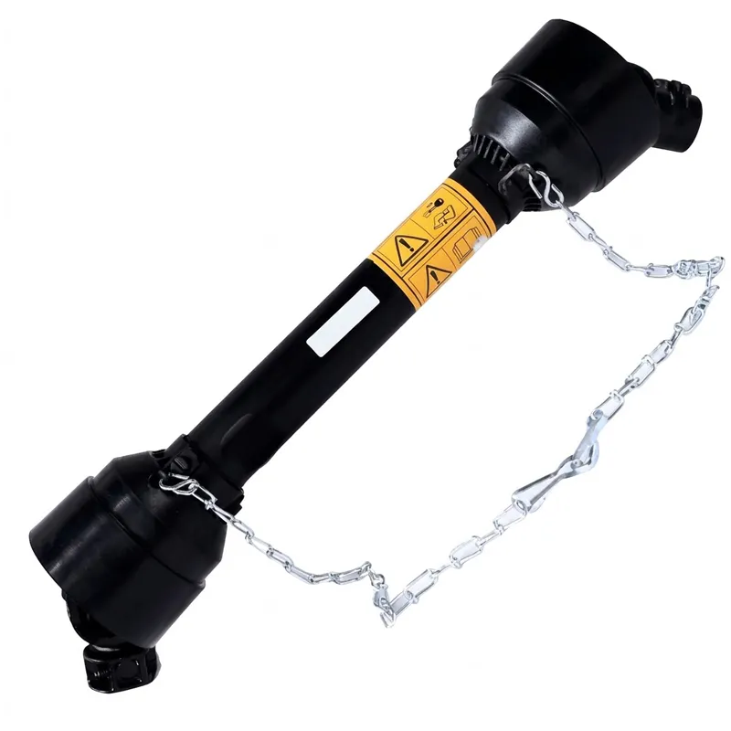
स्क्वायर बेलर के लिए पीटीओ शाफ्ट
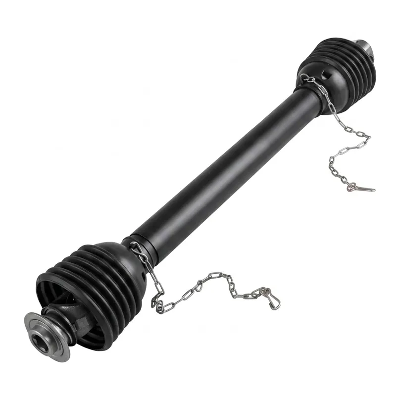
राउंड बेलर के लिए पीटीओ शाफ्ट
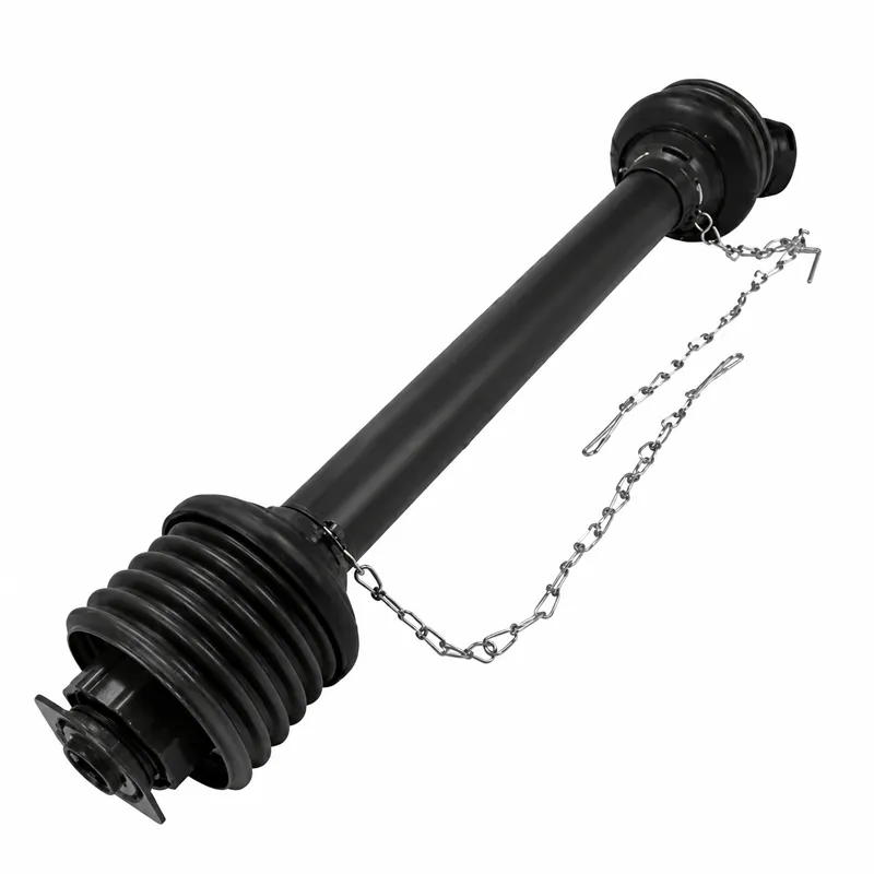
PTO Shaft for Feed Mixers
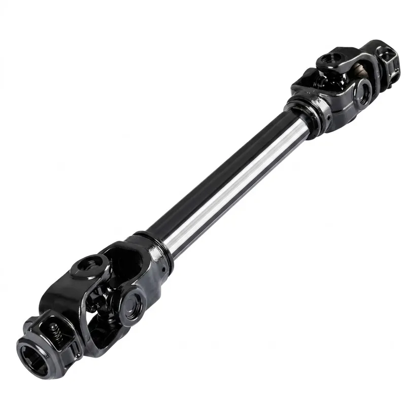
यूनिवर्सल पीटीओ ड्राइवशाफ्ट
पीटीओ शाफ्ट कैसे काम करता है?
The PTO shaft operates on a mechanically simple principle — but its engineering details determine torque capacity, vibration level, service life, and operator safety. Five sequential stages define the complete power flow every time the tractor PTO is engaged.
Tractor PTO Engagement
The operator engages the tractor's PTO lever, coupling the gearbox output to the PTO stub shaft. Engine torque — at 540 or 1,000 rpm — is now available at the rear spline for this drive assembly to transmit.
U-Joint Power Transfer
The tractor-end universal joint accepts the torque and transmits it through the cross-and-bearing assembly to the driveline tube, accommodating the small angular misalignment between tractor PTO stub and the shaft's centre-line axis.
Telescoping Length Adjustment
As the tractor moves relative to the implement during operation, the outer and inner tubes slide together or apart, maintaining an uninterrupted mechanical connection across the range of working distances. Profile tube geometry (triangular, lemon, or star) prevents rotation between inner and outer tubes.
Overload Protection
If torque exceeds the rated threshold — through a blade strike, material blockage, or sudden resistance — the clutch mechanism (friction slip, shear bolt, or ratchet) limits the transmitted force, protecting both the implement gearbox and the tractor's PTO driveline from fatigue damage.
Implement Output Drive
The implement-end U-joint (or wide-angle joint) delivers rotational power to the implement's input shaft — a mower gearbox, baler flywheel, pump impeller, or tiller rotor — completing the mechanical power path from engine to working tool. The stationary outer guard rotates with the inner assembly but is retained independently by safety chains at each end.
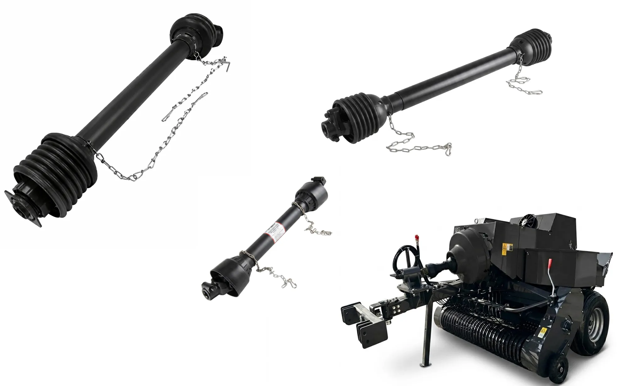
Anatomy of a PTO Shaft
Seven core component groups make up every standard driveline assembly. Material grade and dimensional precision in each group directly determines torque capacity, service life, and safety compliance.
Yoke (Tractor-end & Implement-end)
Forged steel yokes connect to the tractor PTO stub and the implement input shaft via splined bores and a locking groove (spring pin or quick-release collar). The yoke ears carry the U-joint cross-and-bearing assembly and are the highest-stress components in the assembly.
Universal Joints (U-Joints)
A forged cross with four needle-bearing cups allows rotational power to pass through an angular deflection of up to 15° (standard) or up to 80° (wide-angle CV joint). U-joint needle bearings are grease-nipple lubricated and are the most frequently replaced wear item in any driveline.
Profile Tubes (Inner & Outer)
Cold-drawn steel tubes in triangular, lemon (oval), star, or splined-round profiles allow the inner tube to slide axially within the outer tube while transmitting torque without slip. Profile accuracy governs how smoothly the assembly telescopes under load and determines the maximum tube bending moment the assembly can resist.
Safety Guard & End Cones
The plastic outer guard rotates freely around the driveline and is held stationary relative to the ground by a safety chain or bracket at each end. Guard integrity is a legal safety requirement in all jurisdictions — a broken or missing guard renders the unit non-compliant for agricultural or commercial operation.
Torque Limiter / Overload Clutch
Mounted between the implement yoke and the inner tube, the torque limiter is the shock absorber of the entire drive system. Friction disc, shear bolt, and ratchet cam types differ in reset method, repeatability, and cost — selection depends on overload frequency and the cost of implement or tractor gearbox repair.
Overrunning Clutch
A one-way cam-and-roller or sprag clutch built into the tractor-end yoke that allows the driveline to overrun — spin faster than the drive shaft is rotating it — when PTO power is cut. This prevents the tractor gearbox from being reverse-driven by a still-spinning implement flywheel or rotor.
Grease Nipples & Lube Fittings
Each U-joint cross carries a grease nipple for needle-bearing lubrication. Some assemblies also have a tube-slide grease point. Correct greasing intervals — typically every 8–10 operating hours in field conditions — are the single most important maintenance action for extending joint life.
Where Is a PTO Shaft Used?
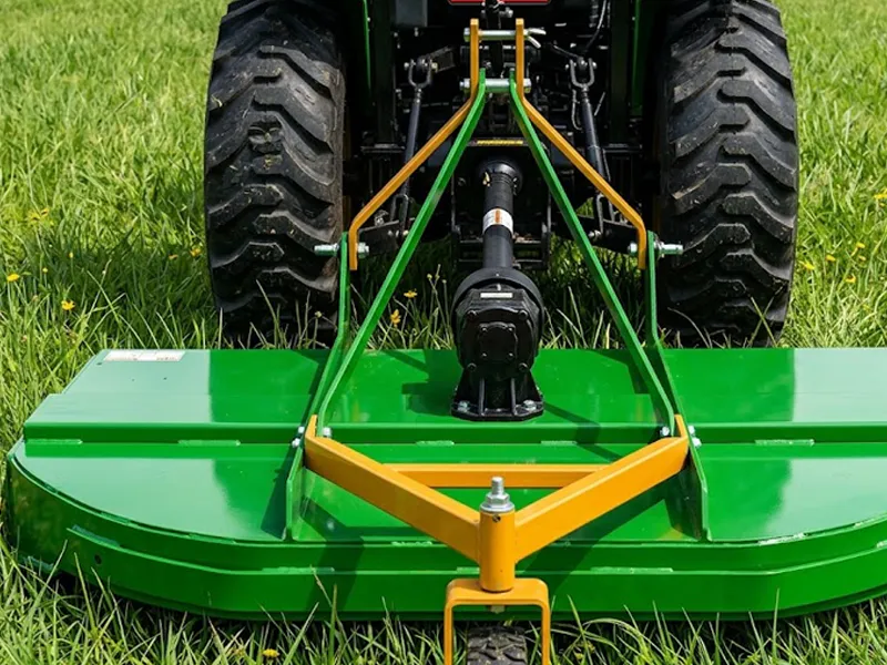
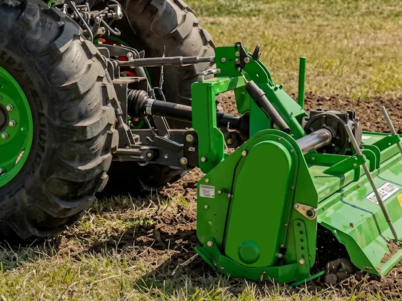
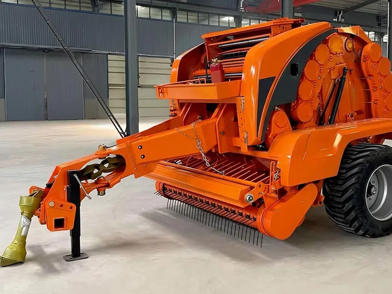
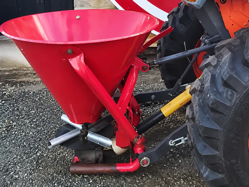
This essential component appears in every category of tractor-powered field equipment. The following represent the five highest-volume deployment scenarios globally, each with distinct specification requirements for the drive unit.