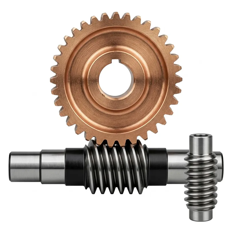
EP-Brass Worm Wheel
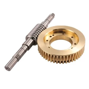
The EP-Brass Worm Wheel is a precision-engineered transmission component crafted from high-quality Brass, offering excellent corrosion resistance and a distinctive yellow finish. Designed for compact mechanical systems, this unit features a Module 0.5 specification with 20 teeth and a teeth diameter of 11.2mm. The wheel has an outer diameter of 11mm, a height of 12mm, and a 4mm bore, with an overall size of 12x11x4mm. It is paired with a matching worm shaft measuring 20mm in height, 9.8mm in outer diameter, and 3.17mm in inner diameter. Weighing only 16g, this lightweight assembly is ideal for small-scale automation, instrumentation, and hobbyist projects requiring reliable, low-friction power transmission in confined spaces.
PRECISION BRASS DRIVE COMPONENTS — WORM GEAR SERIES
A precision-machined brass worm wheel — module M0.5, 20-tooth, hole diameter Ø4 mm, outer diameter Ø11 mm, overall size 12×11×4 mm (H×OD×ID) — paired with a steel worm gear shaft (20×9.8×3.17 mm), delivering quiet, corrosion-resistant, self-lubricating worm and wheel drive for precision instrument, medical device, automation, and hobbyist engineering applications worldwide.
Technical Specifications — EP Brass Worm Wheel Set
Complete dimensional and material specification for the EP series brass worm wheel and matched steel worm gear shaft.
General Specifications
| Parameter | Value |
|---|---|
| Material | Brass |
| Color | Yellow |
| Modulus | 0.5 |
| Weight | 16 g |
Brass Worm Wheel Dimensions
| Dimension | Metric | Imperial |
|---|---|---|
| Teeth | 20 | — |
| Teeth Diameter | 11.2 mm | 0.44 inch |
| Height | 12 mm | 0.47 inch |
| Outer Diameter | 11 mm | 0.43 inch |
| Hole Diameter | 4 mm | 0.16 inch |
| Step Size (Dia × H) | 9×7 mm | 0.35×0.27 inch |
| Overall Size (H × OD × ID) | 12×11×4 mm | 0.47×0.43×0.16 inch |
Steel Worm Gear Shaft Dimensions
| Dimension | Metric | Imperial |
|---|---|---|
| Height | 20 mm | 0.79 inch |
| Outer Diameter | 9.8 mm | 0.39 inch |
| Inner Diameter | 3.17 mm | 0.12 inch |
| Overall Size (H × OD × ID) | 20×9.8×3.17 mm | 0.79×0.39×0.12 inch |
What Is a Brass Worm Wheel — and Why Choose Brass?
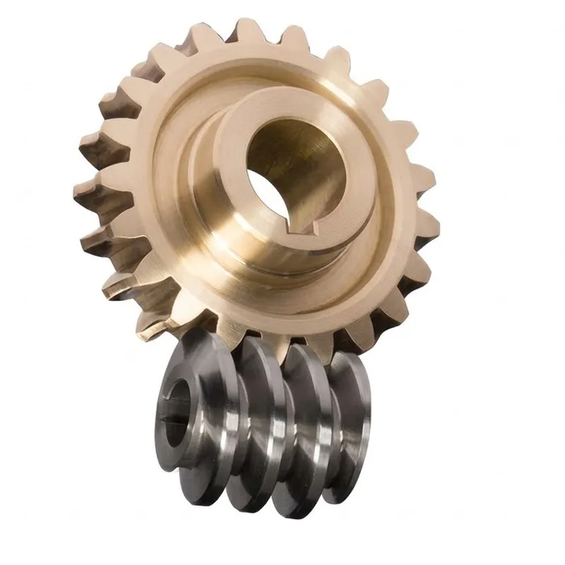
A brass worm wheel is the driven element in a worm and wheel gear mechanism — a toothed disc whose tooth profile is shaped to engage the helical thread of a mating worm screw, converting the worm's rotary motion through a 90° direction change at a high reduction ratio. What is a worm wheel? It is specifically the wheel element of the worm and worm wheel pairing: the worm drives, and the worm wheel is driven. The combination constitutes a worm and wheel mechanism in which a single gear stage achieves ratios of 5:1 to 70:1 or more, with an inherent self-locking function at low lead angles that prevents the output shaft from back-driving the input when the motor is de-energised. Why is it called a worm gear? The worm screw's helical thread resembles the body of a worm, and the name has remained standard in mechanical engineering terminology for centuries.
Among metal worm wheel materials, brass occupies a distinctive position. Brass — a copper-zinc alloy, yellow in colour — offers a combination of machinability, corrosion resistance, low sliding friction against steel, and natural lubricity that makes it the traditional material of choice for the worm wheel in precision instrument drives, scientific equipment, telescope mounts, and camera pan-tilt mechanisms globally. The EP brass worm wheel at module M0.5 with 20 teeth and a 16 g weight represents the miniature end of the worm wheel gear spectrum — a component designed for compact mechanism applications where dimensional accuracy, material quality, and reliable engagement with the steel worm gear shaft are all critical to system performance.
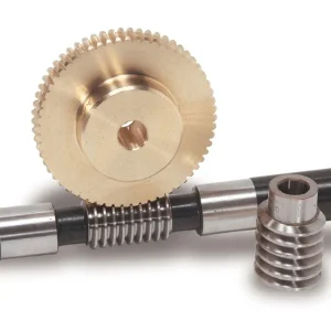
The EP series brass worm wheel is supplied as a matched worm and worm wheel set: the brass worm wheel (Teeth Dia 11.2 mm, Height 12 mm, Outer Diameter 11 mm, Hole Diameter 4 mm, Step Size 9×7 mm, Overall Size 12×11×4 mm) paired with a steel worm gear shaft (Height 20 mm, Outer Diameter 9.8 mm, Inner Diameter 3.17 mm, Size 20×9.8×3.17 mm). Together they form a complete, ready-to-install worm and wheel drive pair at module M0.5, total weight 16 g.
Five Engineering Advantages of the EP Brass Worm Wheel
① Natural Low Friction Against Steel — Self-Lubricating Mesh
Brass exhibits a coefficient of friction against hardened steel of approximately 0.10–0.15 in dry running, dropping below 0.08 with minimal lubrication. This makes the brass worm wheel the traditional standard for worm and wheel drives that must operate without a continuous oil bath — camera mechanisms, scientific instruments, telescope drives, and small actuators where lubricant migration would contaminate optical surfaces or adjacent electronics. The low friction is inherent to the material rather than applied through a surface treatment, so it is maintained throughout the service life of the gear pair as long as the tooth flanks remain within their wear limit.
② Excellent Machinability at Small Module Sizes
Free-cutting brass alloys used in the EP series brass worm wheel rank among the most machinable metals in engineering — significantly easier to hobbing and profile-grind at module M0.5 than stainless steel, tool steel, or even aluminium alloy. This machinability advantage translates directly into the tooth-form accuracy achievable at miniature scale: at module M0.5 with a teeth diameter of 11.2 mm and 20 teeth, the brass worm wheel's involute profile can be hobbed to a precision that would require specialist grinding operations to achieve in steel, while remaining economical in production quantities. The result is a precise, repeatable worm wheel gear tooth form at a scale where material machinability is the primary factor governing achievable accuracy.
③ Corrosion Resistance Without Coating
Brass forms a stable patina of copper oxide and zinc oxide on its surface that resists atmospheric corrosion, salt fog, and mild chemical exposure without requiring plating, painting, or passivation treatment. In a brass worm wheel drive, this means the gear tooth flanks maintain their dimensional accuracy in humid laboratory environments, outdoor instrument housings, and marine navigation equipment without the coating thickness variation that can affect mesh quality in plated steel worm wheel gear sets. The yellow colour of brass also provides easy visual identification of the worm wheel component against the typically silvery steel worm shaft in a gear assembly inspection.
④ High Gear Ratio in Minimal Package — Do Worm Gears Increase Torque?
Do worm gears increase torque? Yes — the worm and wheel mechanism both reduces speed and multiplies torque proportionally. A 20-tooth brass worm wheel driven by a single-start worm gives a 20:1 ratio: motor speed drops by a factor of 20, and output torque rises by the same factor (less friction losses). At module M0.5 and an overall size of 12×11×4 mm, this 20:1 torque multiplication is achieved in a package small enough to fit inside a handheld instrument, a compact actuator housing, or a miniature robot joint — making the worm and wheel gear the most space-efficient torque multiplier available at this scale.
⑤ Matched Steel Worm Shaft — Complete Ready-to-Install Set
The EP brass worm wheel is supplied as a matched pair with the steel worm gear shaft (20×9.8×3.17 mm), pre-verified for module M0.5 mesh compatibility. Supplying a matched worm and worm wheel set — rather than the worm wheel alone — eliminates the dimensional verification burden on the customer's engineering team and avoids the fitment risk of pairing components sourced separately. The steel shaft's 3.17 mm inner diameter is machined to accept a 3 mm motor shaft directly, making the set compatible with common N20 and N30 gear motor shafts widely used in robotics, RC vehicles, and compact automation equipment in the UK, Germany, Japan, and Australia.
Material Profile — Brass in Precision Worm Wheel Applications
What is a worm wheel, and what makes brass the right material for it? The worm wheel is the slower-moving, higher-torque element of the worm and wheel gearbox. In the sliding-contact mesh of a worm drive, it is the worm wheel tooth that experiences the majority of the wear — the worm thread slides across the wheel tooth flank throughout the engagement cycle, generating heat and abrasive contact. Brass's material properties address each of the resulting engineering challenges in miniature worm wheel gear applications with a effectiveness that no comparable-cost material can match.
Tribological Performance — Low Galling Against Steel
Brass and steel form a low-galling tribological pair — the dissimilar metal combination resists cold welding and adhesive wear at the tooth contact interface far better than steel-on-steel or aluminium-on-steel. This property is particularly important in the brass worm wheel application because the sliding-dominant contact at the worm mesh creates conditions that promote adhesive wear in harder material combinations. Free-cutting brass alloys in the CuZn39Pb3 or C360 grade family — the standard for precision gear production — deliver a Brinell hardness of approximately 120–150 HB alongside the low galling tendency that makes them the preferred worm wheel material against a hardened steel worm in instrument and actuator drives across Germany, Japan, Canada, and Australia.
Strength and Conformability
Brass has a tensile strength of approximately 380–420 MPa and a yield strength around 200 MPa for free-cutting grades — positioning the brass worm wheel above polymer alternatives in load capacity while remaining below hardened steel. This moderate strength level brings a practical advantage: under initial run-in loading, the brass tooth flank conforms slightly to the mating steel worm thread form, broadening the contact patch and reducing peak contact stress — a controlled break-in that improves the long-term wear life of the gear pair. This conformability characteristic is one reason brass worm wheel suppliers have maintained the material as the global standard for precision worm wheel gear sets for well over a century.
Dimensional Stability and Machinability
Brass's low coefficient of thermal expansion (approximately 19 µm/m·K for CuZn39) and negligible moisture absorption — in contrast to nylon worm gear materials that absorb 1–3% moisture and expand proportionally — means the brass worm wheel maintains its bore fit and tooth pitch accuracy across the temperature and humidity ranges typical of laboratory instruments, outdoor equipment, and marine applications. The ease of CNC hobbing in brass at module M0.5 allows the 20-tooth profile to be machined to a tooth-to-tooth pitch error below 0.01 mm as-machined — without the additional grinding operations that would be required to achieve the same accuracy in steel.
All EP brass worm wheel components are produced under our ISO 9001:2015 certified quality management system, with material certificates confirming the brass alloy composition and a dimensional inspection report available on request for each production batch.
How the Brass Worm Wheel Works — Worm and Wheel Mechanism Explained
What is worm and worm wheel in practical mechanical terms? The worm screw (steel worm gear shaft) rotates on its own axis, and its helical thread pushes against the tooth flanks of the brass worm wheel. Each full revolution of the worm shaft advances the worm wheel by exactly one tooth — so a 20-tooth brass worm wheel advances 1/20 of a revolution per worm rotation, giving the 20:1 reduction ratio at module M0.5. The worm shaft and wheel axes are perpendicular (90°), and the gear set transmits torque through this right-angle intersection in a space that would require three or four spur gear stages to replicate the same ratio.
What are the worm and worm wheel uses in practice? The worm and worm wheel mechanism serves three core engineering functions simultaneously: speed reduction (the 20:1 ratio), torque multiplication (output torque rises in proportion to the ratio, less friction losses), and direction change (input and output shafts cross at 90°). In addition, at module M0.5 with a single-start worm, the lead angle of the worm thread is low enough to be self-locking: the brass worm wheel cannot drive the steel worm shaft in reverse under static load. This self-locking property is exploited in camera pan-tilt mechanisms, antenna positioners, and precision instrument stages where the output position must hold without continuous motor current.
What are the disadvantages of worm gears? The main limitations of the worm and wheel mechanism are: lower efficiency than spur or helical gear stages (typically 60–80% for a single-start worm at this ratio), heat generation under sustained high-load operation that requires adequate thermal management, and the fact that the mechanism is irreversible (the wheel cannot drive the worm) in self-locking configurations. For the miniature applications served by the EP brass worm wheel at module M0.5 — intermittent-duty instrument drives, hobbyist mechanism builds, and light actuators — these limitations are well within the acceptable range, and the self-locking property is more often an advantage than a constraint.
Application Scenarios — Where Brass Worm Wheels Are Specified
The EP brass worm wheel at module M0.5 serves the miniature end of the worm wheel gear application spectrum — applications where small size, quiet operation, lubricant-free mesh, and self-locking position hold are all required simultaneously in a sub-20 g component package.
Precision Scientific Instruments
Spectrometer grating adjustment drives, microscope objective turret mechanisms, and telescope focuser and polar alignment drives have used the brass worm wheel as the standard worm wheel gear material for over a century. The lubricant-free mesh prevents oil migration onto optical surfaces, the 20:1 ratio provides fine adjustment resolution per motor step, and the self-locking property holds the focus position between manual adjustments. Buyers sourcing worm wheel suppliers for scientific instrument repair and manufacture in Germany, Japan, and the UK routinely specify module M0.5 brass worm wheels for these legacy applications.
Camera Pan-Tilt and Security Systems
CCTV camera pan-tilt heads, telescope mount drives, and photography gimbal mechanisms use the brass worm wheel paired with a steel worm gear shaft for their ability to hold camera pointing direction without continuous motor current — reducing power consumption and motor heating in battery-powered mobile gimbal systems. The 20:1 reduction from a 20-tooth brass worm wheel provides sufficient torque multiplication for a small stepper motor to smoothly reposition a camera head, and the quiet sliding-contact mesh produces less acoustic noise than a spur gear equivalent at the same reduction ratio.
Robotics and Hobbyist Engineering
N20 and N30 DC gear motor output stages, Arduino and Raspberry Pi robot joint drives, and DIY automation mechanism builds use the EP brass worm wheel set for compact right-angle reduction in robot arm wrist joints, small conveyor models, and precision positioning rigs. The 3.17 mm inner diameter of the matched steel worm shaft is compatible with 3 mm motor shafts — the standard output diameter for N20/N30 motors widely used in robotics and maker-space engineering projects in Canada, Australia, the UK, and South Korea.
Automotive Accessories and Mechanisms
Automotive window winder mechanisms, seat adjustment drives, and dashboard instrument pointer drives used the worm and wheel mechanism with a brass worm wheel as the standard configuration for decades in vehicle designs across Germany, Japan, and North America before electric power assistance became universal. The worm and wheel steering gear — still used in heavy trucks and buses — relies on the same brass wheel against steel worm principle at a larger module size. The EP series module M0.5 version serves the replacement and hobby restoration market for vintage vehicle mechanisms and scale model automotive drives.
Medical and Laboratory Equipment
Syringe pump drive stages, laboratory autosampler carriage drives, and diagnostic instrument focus mechanisms specify the brass worm wheel for its lubricant-free mesh — eliminating the oil-migration contamination risk in equipment that handles reagents, samples, or patient-adjacent contact surfaces. At module M0.5 the 20-tooth worm wheel provides fine positional resolution per motor step in dosing and sample carriage drives where each step must correspond to a precise, repeatable displacement volume or distance. These applications are well-established in medical device OEM supply chains in Europe and North America.
Consumer Electronics and Home Appliances
Motorised camera lens barrels, rotating display stands, smart home window blind actuators, and electric curtain rail drives use worm wheel gear sets in brass at small module sizes for their quiet, self-locking operation. The worm and wheel drive's acoustic advantage — inherently quieter than a spur gear pair at the same reduction ratio due to the sliding-contact mesh — is a direct competitive specification in consumer products where acoustic comfort is an explicit customer expectation, particularly in bedroom and living room smart home applications in Canada, Australia, and the UK.
Related Products — Complete Drive System Supply
Beyond the EP brass worm wheel series, we manufacture the complementary drive components that complete a full drive train specification at the same ISO 9001:2015 quality level.
Double Helical Gear
In drive trains where a brass worm wheel stage provides the final right-angle reduction and self-locking hold, a double helical gear stage at the motor output provides a first-stage speed reduction with higher efficiency than a second worm stage would permit. The opposing helix angles of the double helical gear cancel axial thrust, keeping the upstream bearing design simple while handling the load at the higher-speed, lower-torque stage upstream of the brass worm wheel reducer. Single-supplier procurement of both stages simplifies engineering documentation and quality certification management for OEM machine builders globally.

Gear Rack
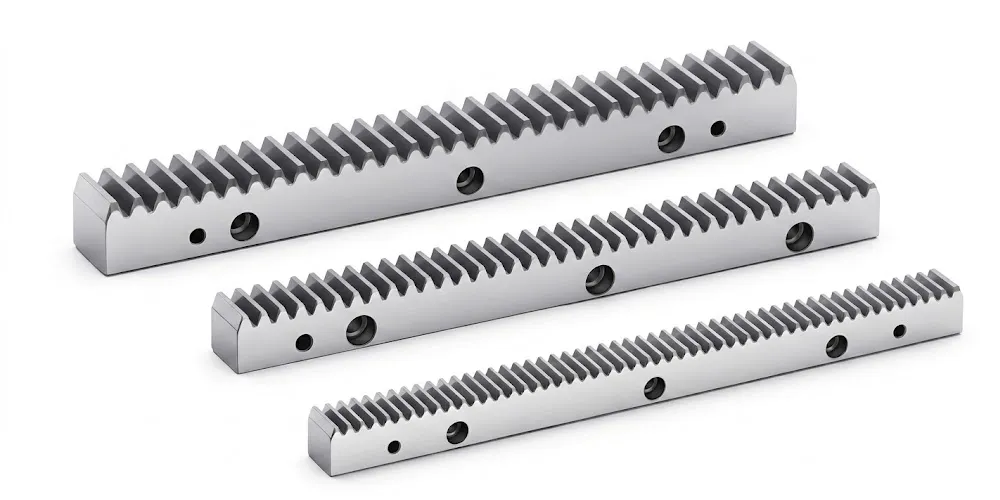
Where the rotary output of a brass worm wheel drive stage must be converted to linear motion — as in a miniature linear actuator, a laboratory stage traverse drive, or a precision positioning mechanism — our gear rack series provides the matching pinion-to-rack interface at the worm wheel output shaft. Metric module gear racks in steel, stainless steel, and polymer grades are available at module sizes compatible with the pinion spur gear on the brass worm wheel output. Single-source supply of the worm and wheel stage and the linear output rack reduces procurement complexity for small-mechanism OEM product development programmes worldwide.
Order and Trade Information
Minimum Order Quantity
Standard brass worm wheel sets carry a baseline MOQ. Mixed configurations — different module sizes, tooth counts, and bore diameters — can be combined into a single order totalling approximately USD 1,500, allowing customers to evaluate several variants simultaneously. For engineering or prototype evaluation, 1–5 pcs samples are available at sample pricing. Very small orders of 1–2 pcs for urgent repair or prototype requirements can be assessed individually, with per-unit cost higher at sub-baseline quantities.
Lead Time
Standard catalogued brass worm wheel configurations: 10–25 working days. Standard parts with bore modification or custom hole diameter: 15–35 working days. Custom OEM/ODM brass worm wheel sets from customer drawing: 20–45 working days. Sample and test-piece orders (1–5 pcs): 7–25 working days, with complex or non-standard configurations assessed individually before production confirmation.
Incoterms and Payment
Standard component orders: EXW, FOB, CIF, and DAP available. Samples and urgent spare parts: EXW / FCA / DAP / courier service. FCA, CFR, CPT, CIP, and DDP negotiable for established procurement programmes or specific import markets. Payment: T/T (bank transfer) and L/C (letter of credit) both accepted. Packing: Plastic bag + Cartons standard; Wooden Packing available for bulk or heavy shipments on request.
OEM / ODM Programme
Full OEM and ODM custom brass worm wheel production from customer engineering drawings, DXF/STEP files, or physical samples for reverse engineering. MOQ for custom configurations depends on tooth count, module, bore diameter, and batch size. Drawing approval precedes production release. Full material and dimensional certification documentation is provided at delivery, supporting medical device and scientific instrument OEM qualification requirements in regulated supply chains globally.
About Our Manufacturing Expertise
With over ten years of specialised experience in precision mechanical power transmission, our facility designs and produces a comprehensive range of industrial drive components under a unified ISO 9001:2015 certified quality management system. Our manufacturing portfolio covers agricultural gearboxes, worm gear reducers, planetary drive units, power take-off shafts, hydraulic cylinders, drive chains, gears of all types, and industrial motors — all built in-house with full dimensional traceability.
On the structural side we cast and machine components in ductile iron, grey cast iron, cast steel, precision cast steel, and cast aluminium for gearbox housings and large gear blanks. Our component range includes gears, sprockets, worm gears, pulleys, shafts, worms, and all standard and non-standard mechanical parts. For the EP brass worm wheel series, we operate CNC gear hobbing equipment capable of the module M0.5 miniature worm wheel tooth profile that these precision instrument and actuator applications demand — with matched steel worm shaft production in the same facility for verified set compatibility before shipment.
Direct factory supply — no trading intermediary — keeps documentation packages complete and lead times competitive for customers qualifying our brass worm wheel products in scientific instrument, medical device, consumer electronics, and robotics OEM programmes in Germany, Japan, South Korea, Canada, Australia, and the UK.
WorkShop




Frequently Asked Questions
Editor: PXY