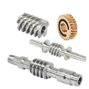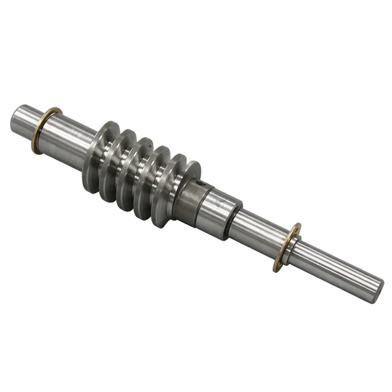
EP-Customized Worm Shaft | Worm Gear Shaft
The worm gear shaft is the driving element at the heart of every worm drive transmission. Unlike a standard shaft, a worm gear shaft integrates the helical thread form — the worm — directly onto the shaft body, creating a single rigid component that delivers rotational input, generates the reduction ratio, and transmits torque to the mating worm wheel without requiring a separate gear-to-shaft joint.
The EP-Customized Worm Shaft programme covers module sizes M1, M2, M3, M4, M5, M8, M12 and beyond, serving applications from micro worm gear set instrument drives through to industrial-scale worm gearbox hollow shaft configurations. Materials span Brass, C45 Steel, Stainless Steel, Copper, POM, Aluminium, and Alloy grades, each selected on the basis of load capacity, corrosion resistance, and the tribological compatibility required with the mating worm wheel material. Surface treatment options — including Zinc-plated, Nickel plated, Passivation, Oxidation, Anodization, Geomet, Dacromet, Black Oxide, Phosphatizing, Powder Coating, and Electrophoresis — extend service life and adapt the worm gear shaft to environments ranging from food-grade processing lines in Australia to outdoor solar tracking arrays in the Netherlands.
EP-Customized Worm Shaft
Precision-machined custom worm gear shaft components available in modules M1 through M12 and beyond. Manufactured from Brass, C45 Steel, Stainless Steel, Copper, POM, Aluminium, and Alloy to ISO, DIN, ANSI, JIS, BS, and non-standard specifications. Full ODM/OEM capability with tolerances to 0.001mm.
Technical Specifications
The following parameters define the standard production capability for the EP-Customized Worm Shaft. Non-standard modules, special thread forms, and extended shaft lengths beyond catalogue ranges are evaluated per drawing submission.
| Parameter | Specification |
|---|---|
| Model Number / Module | M1, M2, M3, M4, M5, M8, M12, and others as required |
| Material | Brass, C45 Steel, Stainless Steel, Copper, POM, Aluminium, Alloy, and so on |
| Surface Treatment | Zinc-plated, Nickel plated, Passivation, Oxidation, Anodization, Geomet, Dacromet, Black Oxide, Phosphatizing, Powder Coating, Electrophoresis |
| Standard | ISO, DIN, ANSI, JIS, BS, and Non-standard |
| Precision Grade | DIN6, DIN7, DIN8, DIN9 |
| Teeth Treatment | Hardened, Milled, or Ground |
| Tolerance | 0.001mm / 0.01mm / 0.1mm |
| Finish Options | Shot/sandblast, heat treatment, annealing, tempering, polishing, anodizing, zinc-plated |
| Packing | Plastic bag + cartons, or wooden packing |
| Payment Terms | T/T, L/C |
| Production Lead Time | 20 business days for sample; 25 days for bulk order |
| Customisation | ODM / OEM — submit drawing, sample, or engineering brief |
Working Principle of the Worm Gear Shaft
A worm gear shaft operates on the same fundamental principle as any worm and worm wheel assembly, but its performance is inseparably tied to the dimensional precision of the shaft itself. As the worm gear shaft rotates on its journal bearings, the helical thread on its surface sweeps into progressive mesh with the teeth of the worm wheel. Each full rotation of the worm gear shaft advances the wheel by exactly one tooth pitch multiplied by the number of worm thread starts. A single-start worm gear shaft meshing a 40-tooth wheel thus delivers a 40:1 reduction ratio — a ratio that would require multiple cascaded gear stages in a spur or helical arrangement. The worm shaft and worm gear contact is a combined sliding and rolling action that distributes load across multiple tooth flanks simultaneously, which is why well-lubricated worm drives are known for smooth, low-noise operation.
The lead angle of the thread form cut into the worm gear shaft governs two critical properties: transmission efficiency and self-locking capability. At lead angles below approximately 5–6°, the friction at the mesh contact exceeds the tangential force component produced by a load applied at the output, meaning the worm gear shaft cannot be back-driven — the drive becomes self-locking. This property is indispensable in lifting equipment, automated parking systems, and solar panel tilting drives where position must be maintained without continuous motor engagement. At steeper lead angles, efficiency rises — a well-designed worm gear drive shaft with a multi-start thread can achieve mesh efficiencies of 85–92%. Thread forms for this worm gear shaft series include ground teeth that satisfy DIN6 through DIN9 precision classes, with the tightest tolerances reserved for telescope worm gear set drives and semiconductor automation equipment where angular positioning error must be minimised. The gear worm wheel pairing is always evaluated alongside the shaft design, since mismatched tooth geometry or centre distance errors compound directly into backlash and transmission error.
Five Key Advantages of the EP-Customized Worm Shaft
Integral Thread-and-Shaft Construction
Machining the worm thread and shaft journals from a single billet eliminates all concentricity error between the thread axis and the bearing seat axis. This matters significantly in precision worm gear shaft applications — even a 0.01mm run-out at the journal propagates directly into transmission error and vibration at the output. A one-piece worm drive shaft removes that risk entirely, giving the assembled worm and worm wheel a quieter and more accurate drive than any built-up alternative can match.
Multi-Material Availability Across the Same Module Range
The same module M3 or M5 worm gear shaft profile can be produced in C45 steel for a general industrial machine tool, in stainless steel worm configuration for a food processing or marine environment, in brass for a silent optical instrument drive, or in POM for a lightweight parking system actuator where corrosion resistance and low noise outweigh peak torque. This consistent module availability across materials simplifies design work and allows a second-source material to be specified without reworking the mating worm wheel.
DIN6 to DIN9 Precision Class Options
Not every worm gear shaft application demands the same precision investment. A worm shaft assembly driving a bulk-material conveyor in Canada needs reliable load capacity and corrosion resistance — DIN8 or DIN9 is adequate and cost-effective. A worm gear shaft in a semiconductor wafer-handling system in South Korea requires DIN6 or DIN7 ground flanks with a verified tooth profile and pitch error trace. Having the full DIN6–DIN9 range available in production means the precision level is matched to the application, not defaulted to the highest grade at unnecessary cost.
Comprehensive Surface Treatment Portfolio
A worm gear shaft operating outdoors on a solar energy tracker in Australia faces UV, humidity, and salt-laden air that will corrode an untreated steel surface within weeks. The same shaft in an automated parking system in an urban structure deals with oil mist and mechanical wear. Geomet and Dacromet coating systems provide 1,000-hour salt spray resistance for outdoor steel worm gear shaft applications, while Nickel plating and Passivation serve medical device and food equipment environments where hygiene standards restrict certain coatings.
Verified Tolerance Down to 0.001mm
Production tolerances of 0.001mm, 0.01mm, and 0.1mm are available across the module range, with the tightest class supported by CNC grinding operations and verified by coordinate measuring machine (CMM) inspection. For long worm gear shaft designs or double shaft worm gear motor configurations where bearing preload and shaft deflection interact, dimensional verification reports are available as part of the quality documentation package. This level of measurement traceability supports customers in regulated sectors across the UK, Netherlands, and Germany.
Material Selection for the Worm Gear Shaft
The tribological relationship between a worm gear shaft and its mating wheel is the governing factor in material selection — the worm shaft is consistently harder than the wheel to concentrate wear on the more easily replaced component. C45 carbon steel is the entry-level choice for general-duty worm drive shaft applications: it responds well to induction hardening and tempering, reaching surface hardness levels of HRC 45–52 that provide adequate wear resistance when running against a phosphor-bronze or brass worm wheel. Where higher contact fatigue strength is needed — heavy industrial drives, off-highway equipment, or a large worm gear set integration — alloy steel grades provide the additional hardenability needed to reach HRC 58–62 through carburizing or nitriding, which dramatically extends tooth flank life under continuous load.
Stainless steel worm shaft production uses grades such as 304 or 420 depending on whether corrosion resistance or surface hardness is the priority. The 420 martensitic grade can be hardened to around HRC 48, making it a practical metal worm gear shaft option for food processing equipment in the UK and marine winch drives across Australian coastal environments. Brass worm gear shaft builds are the standard for optical instrument drives, telescope worm gear set feeds, and audio equipment positioning stages where near-silent operation is non-negotiable — the inherent damping of brass absorbs vibration that steel transmits. POM and aluminium worm gear shafts serve the lightest duty categories: parking system actuation, solar panel tilt drives, and semi-conductor handling robots where the load is modest and the priority is mass reduction and corrosion immunity without any surface coating. All material choices are evaluated against the target service life, lubrication regime, and operating temperature before production begins.
Application Scenarios
Automatic Controlling Machines
Automated process control systems — valve actuators, dosing pumps, and position-controlled damper drives — rely on a worm gear shaft to combine high reduction ratio with reliable self-locking in a compact envelope. The worm gear and shaft combination in these systems must maintain precise angular position across temperature cycles and extended duty periods without creep or backlash growth. Stainless steel and hardened C45 steel worm shaft assemblies dominate this segment, with DIN7 or DIN8 precision grades meeting most automatic control machine requirements without the cost premium of fully ground DIN6 flanks.
Semi-Conductor Industry
Wafer transport stages, mask alignment mechanisms, and die bonding head positioners in semiconductor manufacturing facilities in South Korea, Japan, and Taiwan incorporate miniature worm gear set configurations built around precision worm gear shafts at M1 and M2 module sizes. Cleanroom compatibility demands materials and surface treatments — passivation, anodization — that produce no particulate contamination, and the positional accuracy required at nanometre-level process steps demands DIN6 ground tooth profiles on the worm gear shaft and a backlash-controlled wheel mesh.
Medical Equipment
Surgical robot joints, hospital bed height adjustment drives, and ophthalmic examination chair positioning systems across healthcare facilities in the UK, Canada, and the Netherlands all use worm gear shaft assemblies to achieve quiet, self-locking, and sterilisation-compatible positioning. Stainless steel worm shaft builds with nickel plating or passivation satisfy the chemical exposure requirements of autoclave cycles, and the inherent self-locking of the worm drive shaft means patient positioning is maintained passively without additional electromagnetic braking hardware.
Solar Energy Equipment
Single-axis and dual-axis solar tracker drives are one of the largest growing applications for heavy-duty worm gear shafts worldwide. The worm drive shaft in a solar tracker must withstand sustained wind loading on the panel array, resist outdoor corrosion from rain and humidity in Australian and Brazilian climates, and maintain its angular position without power under normal standby conditions — a role tailor-made for the self-locking worm and worm wheel mechanism. Geomet or Dacromet-coated worm gear shafts in C45 or alloy steel are the standard specification for utility-scale tracker installations.
Parking Systems
Automated multi-storey parking structures use worm gear shaft drives in the lifting and lateral transfer carriages that move vehicles without driver input. The requirements are demanding: the worm gear drive shaft must handle impact loading as vehicles are placed, resist the damp and grit present in underground car parks, and hold vehicle weight statically when the motor is off — which the self-locking property of a properly specified worm gear shaft achieves without any additional holding brake. Urban parking system builders across Germany and the Netherlands specify powder-coated alloy steel worm shaft assemblies for their combination of load capacity, corrosion resistance, and passive position holding.
About Us — 10+ Years of Precision Gear Manufacturing
This facility has spent more than a decade building expertise across the full spectrum of mechanical power transmission components. The product range encompasses agricultural gearboxes, worm gear reducers, planetary gear drives, power take-off shafts, hydraulic cylinders, gears, chains, and electric motors. Every process from raw material sourcing through to final inspection operates under ISO 9001:2015 certification, providing the quality management discipline that regulated-sector customers require. Production capabilities span the full material matrix for industrial and agricultural gearboxes and assemblies — ductile iron, cast iron, cast steel, precision cast steel, and cast aluminium — as well as gears, sprockets, worm gears, pulleys, worm shafts, and non-standard mechanical parts engineered to customer drawings.
Related Products — One-Source Drivetrain Supply
A worm gear shaft is most effective when the surrounding drivetrain components are engineered with the same dimensional care. Secondary gear stages and rack-and-pinion final stages sourced from the same manufacturer as the worm shaft eliminate tolerance stack-up at interfaces and reduce commissioning time on site.
Double Helical Gear
When a worm gear shaft drives a primary reduction stage and a second reduction is needed on the output shaft, double helical gears are the preferred parallel-axis option. The opposed helix angles cancel axial thrust, making them easy to integrate without additional thrust bearings on the shaft. Steel and alloy steel variants are available across multiple modules, with centre distances that can be specified to match the output journal of your worm gear and shaft assembly. This combination — worm primary reduction and double helical secondary — delivers very high overall ratios in a two-stage design that remains compact and audibly quiet.

Gear Rack
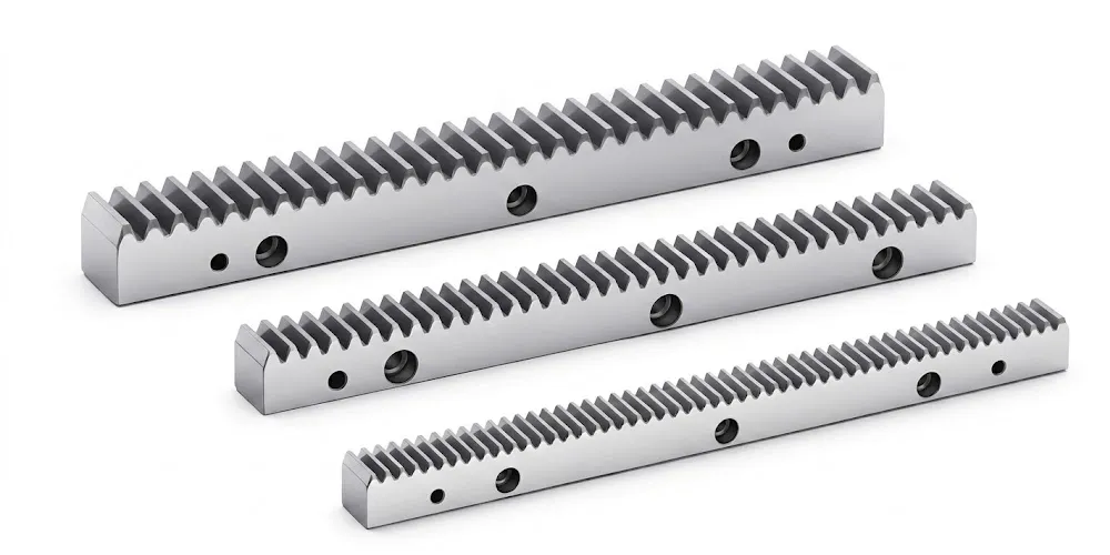
A gear rack coupled to the output pinion of a worm wheel shaft creates an efficient linear motion system where the worm gear shaft provides the reduction and passive position-holding and the rack delivers the travel stroke. This architecture appears in CNC machine tool axes, automated parking system platforms, and warehouse automation gantries — all sectors where worm gear shaft drives are already specified for their self-locking property. Full-series gear racks in steel, stainless steel, and polymer are available with module pitches selectable to integrate with the pinion dimensions on your specific worm shaft assembly output.
Trade & Delivery Terms
| Item | Detail |
|---|---|
| MOQ | MOQ depends on drawing, material, tolerance, machining process and batch size. Mixed models can be combined to reach around USD 1,500. 1–2 pcs orders can be evaluated, but unit cost may be higher. |
| Sample Policy | 1–5 pcs samples available for new customers. Sample lead time: 20 business days. Sample express shipping cost paid by client. |
| Lead Time — Standard / Light Custom | 20–45 working days |
| Lead Time — High-Precision / Heat-Treated Worm Gear Shaft | 30–60 working days |
| Bulk Production Lead Time | 25 working days (standard modules); extended for complex custom worm shaft assemblies |
| Trade Terms | EXW, FOB, CIF, DAP standard; FCA, CFR, CPT, CIP, DDP negotiable |
| Recommended Terms | EXW / FOB / CIF / DAP for custom CNC and OEM worm gear shaft orders |
| Payment | T/T, L/C |
| Delivery Carriers | DHL, TNT, FedEx, UPS; sea freight for larger worm shaft batch orders |
| Packing | Plastic bag + cartons, or wooden packing per customer requirement |
Frequently Asked Questions
What is a worm gear shaft and how does it differ from a standard gear shaft in an industrial gearbox application?
Which worm gear shaft material is best suited for outdoor solar energy tracking equipment installed in high-humidity coastal regions of Australia?
How do I select the right module size for a custom worm gear shaft when designing a conveyor drive for a food production line in the UK?
Where can manufacturers in Canada source long worm gear shaft components with OEM documentation for heavy-duty agricultural machinery?
How should I maintain a worm gear shaft assembly in an automated parking system to maximise service life in an underground urban structure?
Editor: PXY