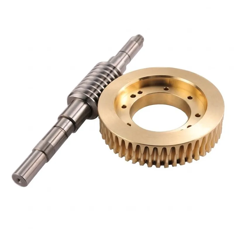
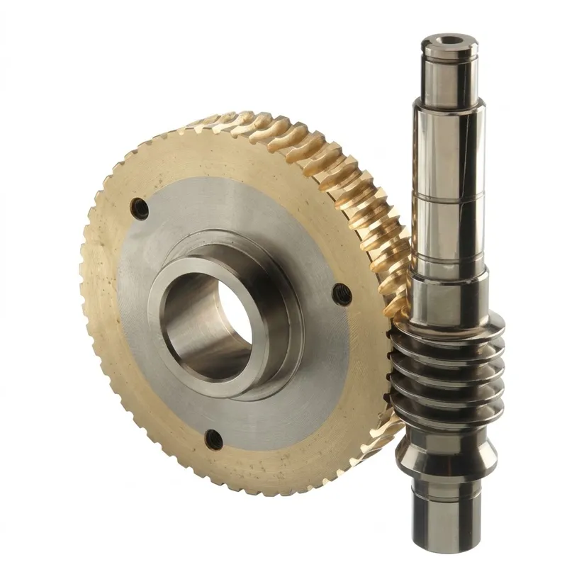
EP-Worm and Wheel
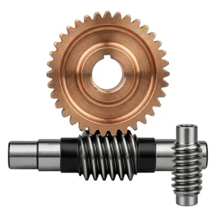
The EP-Worm and Wheel series delivers high-precision transmission solutions for diverse industrial applications, including CNC machinery, semiconductor equipment, and medical devices. Available in modules from M3 to M12, these gears are manufactured from premium materials like Brass, C45 Steel, Stainless Steel, Copper, POM, and Aluminum. They adhere to international standards (ISO, DIN, ANSI, JIS) with precision grades ranging from DIN6 to DIN9. Teeth undergo specialized treatments such as hardening, milling, or grinding, achieving tight tolerances between 0.001mm and 0.1mm. Surface finishes include zinc plating, anodizing, black oxide, and powder coating for enhanced durability. With a production lead time of 20 days for samples and 25 days for bulk orders, this series supports flexible payment terms (T/T, L/C) and is ideal for automation, solar energy, and high-speed rail systems requiring reliable, corrosion-resistant performance.
PRECISION INDUSTRIAL DRIVE COMPONENTS — WORM GEAR SERIES
EP-Worm and Wheel
A comprehensive precision worm and wheel series — Brass, C45 steel, Stainless steel, POM, Aluminum Alloy, and Copper; modules M3 through M12; DIN6 to DIN9 precision grades; certified to ISO, DIN, ANSI, JIS, and BS standards — engineered for automatic controlling machines, semiconductor equipment, medical devices, solar drives, machine tools, parking systems, and high-speed rail transportation worldwide.
Technical Specifications — EP Worm and Wheel Series
Full parameter reference for the standard EP series. Custom module, material, surface treatment, and non-standard configurations available through our OEM/ODM programme.
| Parameter | EP Series Specification | Notes |
|---|---|---|
| Product Type | Worm and Wheel (worm screw + worm wheel set) | Right-angle drive pair |
| Model Number | M3, M4, M5, M8, M12 and more | Metric module series |
| Material | Brass, C45 steel, Stainless steel, Copper, POM, Aluminum Alloy and more | As customer specified |
| Surface Treatment | Zinc plated, Nickel plated, Passivation, Oxidation, Anodization, Geomet, Dacromet, Black Oxide, Phosphatizing, Powder Coating, Electrophoresis | Per environment/requirement |
| Standard | ISO, DIN, ANSI, JIS, BS, Non-standard | Multi-standard certified |
| Precision Grade | DIN6, DIN7, DIN8, DIN9 | DIN 3962 accuracy class |
| Teeth Treatment | Hardened, Milled, or Ground | Per precision class required |
| Tolerance | 0.001 mm / 0.01 mm / 0.1 mm | Three tolerance tiers |
| Finish Options | Shot/sand blast, heat treatment, annealing, tempering, polishing, anodizing, zinc-plated | As specified |
| Packing | Plastic bag + Cartons or Wooden Packing | Export-standard |
| Payment Terms | T/T, L/C | Standard international terms |
| Production Lead Time | 20 business days (sample) / 25 days (bulk) | Complex custom: per project |
| Customisation | OEM / ODM | Drawing or sample accepted |
| Quality Certification | ISO 9001:2015 | Factory-wide QMS |
What Is a Worm and Wheel — and Why Does It Matter?
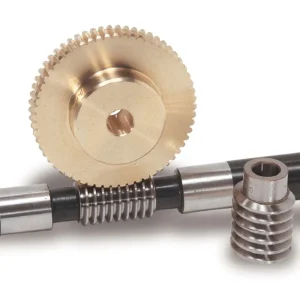
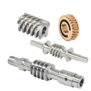
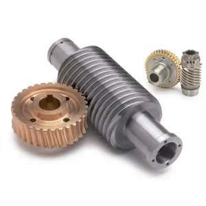
A worm and wheel is the fundamental two-element worm drive pairing: a worm screw (a cylindrical or hourglass-profiled shaft with a helical thread) meshing with a worm wheel (a toothed disc whose tooth form is shaped to engage the worm thread). Together they form the worm and wheel gear mechanism — a single-stage, right-angle speed reduction system that has been a cornerstone of precision machinery design for well over a century. The worm shaft and wheel operate on shafts crossed at 90°, transmitting torque from the rotating worm to the driven worm wheel at gear ratios that can range from 5:1 to 100:1 or higher in a single compact stage.
The EP worm and wheel series covers model numbers M3, M4, M5, M8, M12 and beyond, manufactured in Brass, C45 steel, Stainless steel, Copper, POM, Aluminum, and Alloy. Surface treatments span Zinc plated, Nickel plated, Passivation, Oxidation, Anodization, Geomet, Dacromet, Black Oxide, Phosphatizing, Powder Coating, and Electrophoresis. Standards compliance covers ISO, DIN, ANSI, JIS, BS, and Non-standard configurations. Precision grades run from DIN6 through DIN9. Teeth treatment options include Hardened, Milled, and Ground finishes. Tolerance tiers cover 0.001 mm, 0.01 mm, and 0.1 mm. Finish options include shot/sand blast, heat treatment, annealing, tempering, polishing, anodizing, and zinc-plated. Packing is in Plastic bag + Cartons or Wooden Packing. Payment terms: T/T and L/C. Production lead time is 20 business days for sample and 25 days for bulk. Applications extend across automatic controlling machines, semiconductor industry, general industry machinery, medical equipment, solar energy equipment, machine tool, parking system, and high-speed rail and aviation transportation equipment.
The breadth of this worm and wheel specification — eight documented application sectors, nine surface treatment processes, and six core material families — reflects the product's genuinely cross-industry applicability. Few drive component formats serve simultaneously in precision semiconductor handling equipment and heavy transportation infrastructure. The worm and wheel mechanism achieves this versatility through the fundamental engineering properties built into its geometry: right-angle compactness, high single-stage ratio, self-locking position hold, and quiet sliding-contact mesh.
Five Defining Advantages of the EP Worm and Wheel Series
① High Reduction Ratio in Single Stage — Unmatched Compactness
A single worm and wheel gear stage at module M5 with a 40-tooth worm wheel and a 1-start worm achieves a 40:1 reduction — a ratio that would require three or four spur or helical gear stages to replicate, each requiring its own shaft, bearings, and housing. The worm and wheel mechanism condenses this reduction into a 90° right-angle drive package whose housing footprint is determined by the worm wheel pitch diameter alone. For machine designers specifying drives in medical devices, parking systems, and precision automation equipment where enclosure space is the primary constraint, this single-stage compactness is the worm and wheel's most commercially relevant engineering advantage.
② Nine Surface Treatment Options — Environmental Versatility
The EP series covers nine surface treatment processes — from Zinc and Nickel plating for standard corrosion protection through Geomet and Dacromet for high-corrosion environments, Black Oxide for moderate protection with minimal dimensional change, Anodization for aluminium variants, and Powder Coating and Electrophoresis for colour-coded or aesthetically finished drives. This breadth means the same worm wheel gear tooth geometry can be surface-treated to meet the requirements of outdoor solar tracking equipment in Canada, stainless-washdown food processing lines in Germany, and decorative architectural lifting mechanisms in the UK — all from the same dimensional specification and tooling.
③ Multi-Standard Certification — Global OEM Qualification
Compliance with ISO, DIN, ANSI, JIS, BS, and Non-standard in a single worm and wheel product family eliminates the need for separate localised variants when supplying OEM machinery programmes that ship to multiple markets. A machine tool manufacturer in Japan and an agricultural equipment OEM in Canada can specify the same EP series worm and wheel component without dimensional re-qualification, reducing the engineering burden on their procurement and quality teams. Non-standard configurations are also supported, covering worm and wheel gearbox applications where no published standard module applies to the design envelope.
④ DIN6 to DIN9 Precision — Scalable Accuracy
Precision grades spanning DIN6 through DIN9 allow the correct accuracy class to be matched to the application's positional repeatability requirement and budget without over-specifying. DIN6 with ground teeth and 0.001 mm tolerance serves semiconductor wafer handling stages and high-speed rail drive systems where positional error is safety-critical. DIN9 with milled teeth serves general industry machinery and parking system drives where standard industrial precision is entirely adequate. The worm and wheel gear mechanism's accuracy class is thus a configurable parameter, not a fixed constraint.
⑤ Self-Locking Position Hold — Built-In Mechanical Brake
At low lead angles, the worm and wheel drive is self-locking: the driven worm wheel cannot back-drive the worm screw when the motor is de-energised. This intrinsic mechanical holding function eliminates the need for a separate holding brake or solenoid lock in solar tracker drive stages, parking system lift mechanisms, automatic controlling machine actuators, and aviation ground equipment drives. The self-locking property is a direct function of the thread lead angle and friction coefficient at the mesh — properly designed, it requires no additional components to maintain position under static load for indefinite hold periods.
Material Selection Guide — Matching Worm and Wheel Material to Application
What is the best material for a worm and wheel? The answer depends on the operating environment, load level, speed, and whether corrosion resistance, lubricant-free operation, or maximum tooth strength is the governing specification. The EP series covers six core material families, each targeting a specific combination of these requirements.
Brass — Precision Instrument Standard
The brass worm wheel is the traditional material for precision instrument worm and wheel drives — telescope mount drives, scientific equipment, and camera pan mechanisms. Brass's low friction against a hardened steel worm, excellent machinability at fine module sizes, and inherent corrosion resistance make it the first-choice worm and worm wheel pairing for instrument applications requiring lubricant-free operation globally. The brass worm wheel is also the standard material in the worm and wheel steering gear of older vehicles and marine steering systems.
C45 Steel — Maximum Load Capacity
C45 medium-carbon steel worm wheel gear components, when heat-treated (quenched and tempered or surface-hardened), provide the highest tooth bending and contact fatigue strength in the EP series. The steel worm gear set in C45 or alloy steel is specified for heavy-duty gearbox applications, crane hoist drives, and machine tool main worm drive stages where load capacity is the primary design criterion and the environment does not demand corrosion resistance beyond standard coating protection.
Stainless Steel — Corrosion-Critical Service
A stainless worm gear worm wheel in 304 or 316 grade resists washdown chemicals, saline environments, and process fluids without coating degradation. This is the material of choice for the worm wheel drive in food processing equipment, pharmaceutical conveyor actuators, marine deck mechanisms, and chemical plant valve positioners across regulatory environments in Australia, Canada, and the UK where surface rust is a compliance failure, not merely a cosmetic defect.
POM — Self-Lubricating Polymer
A POM plastic worm wheel (Polyacetal / Delrin) provides the lowest friction coefficient of the polymer options in the EP series, with excellent dimensional stability and low moisture absorption — making it the preferred plastic worm wheel material for small-module worm and wheel stages in office automation, medical device actuators, and precision instrument drives where lubricant contamination is unacceptable. Its bore fit stability over thermal cycling and humidity variation outperforms nylon in these miniature configurations.
Aluminum Alloy — Lightweight Drive Stages
Aluminum alloy worm wheel components reduce the rotating inertia in servo-driven worm and wheel mechanisms — relevant in solar tracker azimuth drives, robotic arm wrist joints, and battery-powered automated guided vehicles where motor power budget and structural weight are both constrained. Anodized surface treatment on aluminium worm wheels provides adequate corrosion resistance for outdoor duty without the weight penalty of a steel or bronze alternative at the same pitch diameter.
Copper — Thermal and Electrical Applications
Copper worm wheel variants serve niche applications where the worm wheel gear must function in an electrically conductive or thermally managed environment — grounding brush mechanisms, thermal dissipation components in power electronics, and specialist scientific instrument worm drives where copper's unique combination of electrical conductivity and machinability at small module sizes is the primary selection criterion.
How a Worm and Wheel Works — Mechanism and Gear Ratio
Why is it called a worm gear? The worm's name comes from its visual resemblance to a worm or screw thread — a helical thread form wound around a cylindrical shaft that meshes with the teeth of the worm wheel in the same way a worm burrows through material, advancing in one linear direction as it rotates. The worm and wheel mechanism uses this thread-tooth engagement to achieve torque multiplication and speed reduction simultaneously: for every full revolution of the worm shaft, the worm wheel advances by exactly one tooth pitch. This means the gear ratio is simply the number of teeth on the worm wheel divided by the number of starts on the worm — typically 1 start, so a 40-tooth worm wheel gives a 40:1 ratio from a single gear pair.
How to find the gear ratio of a worm and wheel is therefore straightforward: divide the number of wheel teeth by the number of worm starts. A multi-start worm (2-start or 4-start) proportionally reduces the ratio — a 2-start worm with a 40-tooth wheel gives 20:1, and permits higher efficiency at the cost of self-locking capability. The EP series supports both single-start and multi-start worm configurations across the M3 to M12 module range, allowing designers to trade between maximum ratio, efficiency, and self-locking as the application requires.
The contact between the worm and worm wheel is sliding-dominant — the worm thread slides across the tooth flank of the worm wheel throughout engagement, unlike the rolling-dominant contact of spur or helical gears. This sliding generates heat under sustained high-load operation, which is why proper lubrication with EP (extreme pressure) gear oil is specified for the metal worm gear worm wheel configurations in the EP series. What are the disadvantages of worm gears? The primary disadvantages are lower efficiency (typically 60–85%) compared to helical or spur stages, and heat generation that must be managed through correct lubricant selection and housing thermal design. These trade-offs are accepted because the compactness, self-locking function, and right-angle geometry of the worm and wheel drive cannot be replicated by any other single-stage gear format.
How to maintain a worm and wheel? Regular lubrication with the correct gear oil grade (EP 680 or equivalent for mineral oil; polyglycol fluids for food-grade applications), periodic inspection of the worm wheel tooth flanks for pitting or scoring, and verification of the worm shaft axial play within the bearing clearance specification are the three fundamental maintenance tasks. For self-locking worm and wheel drives in parking systems and solar trackers, periodic backlash measurement confirms that the tooth wear has not increased beyond the specified limit — at which point field adjustment or worm wheel replacement restores the designed position-hold accuracy.
Application Scenarios — Eight Sectors Where Worm and Wheel Drives Are Specified
The eight documented application sectors in the EP worm and wheel specification reflect the product's genuinely broad industrial reach. Each application below leverages a different combination of the worm and wheel mechanism's core properties — compactness, high ratio, self-locking, right-angle drive, or quiet operation.
Automatic Controlling Machines
Motion-controlled positioning stages, automated assembly jigs, and CNC-driven indexing fixtures use the worm and wheel mechanism for its high reduction ratio in compact enclosures and the self-locking hold that eliminates position drift when the servo is idle. Precision grades DIN6 or DIN7 in brass or C45 steel are the standard specifications for automatic controlling machine drives across manufacturing facilities in Germany, Japan, and South Korea.
Semiconductor Industry Equipment
Wafer handling robots, mask aligners, and semiconductor inspection stage drives specify DIN6 precision worm and wheel sets in POM or aluminium for their combination of sub-micron positioning resolution, lubricant-free mesh (critical in cleanroom environments), and low particulate generation. The self-locking property prevents the stage from drifting when the stage motor is off — a fundamental requirement in semiconductor fab equipment where any uncontrolled movement could damage a wafer or a delicate optical element.
General Industry Machinery
Conveyor head shaft reducers, agitator drives, mixer gearboxes, and packaging machine indexers use steel or cast iron worm and wheel gearbox configurations for their robustness, maintenance simplicity, and the right-angle input-to-output shaft arrangement that conveniently places the motor above or beside the driven shaft without bevel gears. For general industry machinery buyers in Canada, Australia, and Brazil, the combination of low purchase cost and long service interval makes the worm and wheel drive the most commercially dominant reducer format in light-to-medium industrial applications.
Medical Equipment
Infusion pump drives, patient bed positioning actuators, diagnostic instrument traverse stages, and surgical robot wrist joints specify POM or stainless steel worm and wheel sets for their combination of precise reduction, lubricant-free operation in body-adjacent and sterile environments, and self-locking hold between motor steps. Medical device OEM buyers in the EU, USA, and Japan regularly qualify worm and wheel drive components under ISO 13485 and FDA 21 CFR Part 820 frameworks, requiring the material certification and dimensional documentation that the EP series provides as standard.
Solar Energy Equipment
Single-axis and dual-axis solar tracker azimuth and elevation drives use aluminium or stainless steel worm and wheel mechanisms for their inherent self-locking hold — the panel stays pointing at the sun when the tracker motor is off without any additional locking mechanism, reducing system complexity and energy consumption. The worm and wheel drive's high single-stage reduction ratio (40:1 to 80:1 typical) allows a small motor to drive a large solar panel array, and the right-angle geometry places the motor conveniently above the tracker's pivot frame. Solar tracker installations in Australia, Canada, and the UK rely on this configuration at scale.
Machine Tools
Rotary table drives, compound slide feed mechanisms, tailstock advance actuators, and grinding wheel dresser positioners use C45 steel or alloy steel worm wheel gear sets at DIN6 to DIN7 precision for their combination of fine angular positioning, rigidity under cutting loads, and the mechanical braking effect that prevents table or slide movement under cutting forces when the feed axis motor is idle. Machine tool worm and wheel drives are among the highest-precision and highest-load applications in the EP series product range.
Parking Systems
Automated multi-storey car park lift and traversing mechanisms use worm and wheel gearbox drives for the self-locking property that holds the vehicle pallet at each storage level without a separate holding brake. The worm and wheel drive's high reduction ratio allows a low-power motor to lift a vehicle pallet without high motor torque, and the right-angle geometry positions the motor and gearbox compactly within the structural frame of the parking module. Stainless or zinc-plated steel worm wheel gear sets provide the corrosion resistance needed for covered-car-park environments in Canada, Japan, and South Korea.
High-Speed Rail and Aviation Transportation Equipment
Landing gear retraction actuators, flight control surface drives, railway platform door mechanisms, and track switch actuators use precision worm and wheel sets in stainless steel or high-strength alloy steel for safety-critical position-hold requirements. In these regulated transportation applications in Europe, Japan, and North America, the worm and wheel mechanism's self-locking property serves as the primary fail-safe: even if drive power is lost, the mechanism holds its position until manual intervention or powered recovery is possible — a critical safety attribute that few other drive formats provide inherently.
Worm and Wheel Steering, Hourglass Forms, and Special Configurations
Beyond the standard cylindrical worm, the worm and wheel format encompasses several specialised configurations that extend its performance envelope. The worm and wheel steering gear — a classic automotive application — uses a recirculating ball nut or direct worm sector to convert steering wheel rotation into rack movement, with the worm thread providing both the gear reduction and the self-centring property of the steering column. The worm and wheel steering gear box represents one of the oldest continuous applications of the worm drive in transportation, preceding the rack-and-pinion steering gear that now dominates passenger cars but remaining standard in heavy trucks, buses, and military vehicles in Germany, Japan, and North America.
The hourglass worm and wheel configuration — also known as the globoidal worm — uses a worm whose throat profile is concave (hourglass-shaped) rather than cylindrical. This geometry allows multiple tooth pairs to be in contact simultaneously, significantly increasing the load capacity and efficiency of the worm and wheel mechanism compared to a cylindrical worm of equivalent module. The hourglass worm and wheel is specified in high-capacity industrial reducers, printing press drives, and injection moulding machine feed drives where the load exceeds what a standard cylindrical worm and wheel can deliver at the same housing size.
The worm and wheel drive is also inherently bidirectional — the worm can drive the wheel in either rotational direction depending on the thread hand (left or right) and the motor rotation. The self-locking property does not restrict which direction the input rotates; it only prevents back-driving of the worm by the wheel load. This means a single worm and wheel set specified with the correct hand serves both clockwise and counterclockwise output rotation in the same application — simplifying inventory management for multi-axis machine builders who need both rotation directions from a single gear set stock.
Related Products — Complete Drive Train from One Source
The EP worm and wheel series integrates into a complete drive system. We produce the following complementary components at the same ISO 9001:2015 quality level, enabling single-supplier procurement for the full drive train.
Double Helical Gear
For drive trains where a worm and wheel stage handles the final right-angle reduction, a double helical gear stage is often used upstream at the motor output for an efficient first-stage speed reduction. The opposing helix angles cancel axial thrust, simplifying upstream bearing design while delivering the load capacity the motor-adjacent stage needs. Pairing an efficient helical first stage with a compact self-locking worm and wheel final stage is a common design strategy in industrial gearboxes serving machine tool, solar tracking, and automation applications globally.

Gear Rack
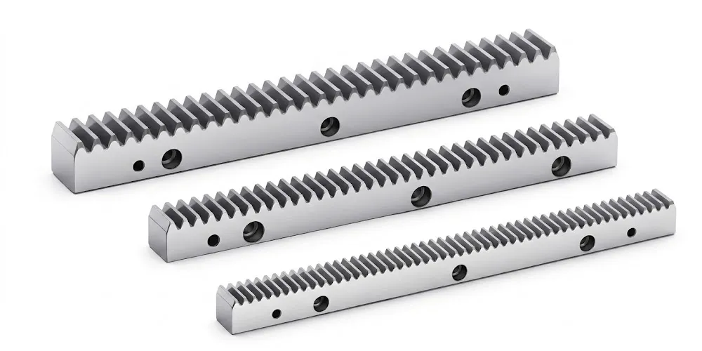
Where the rotary output of a worm and wheel worm wheel drive stage feeds a linear axis — as in a solar tracker linear stroke actuator, a parking system traversing mechanism, or a CNC table longitudinal feed — our gear rack series provides the pinion-to-rack interface at the output shaft. Metric module gear racks in steel, stainless steel, and polymer grades are available at module sizes compatible with pinion spur gears on the worm wheel output. Single-source procurement of the worm and wheel reduction stage and the downstream linear stage reduces qualification effort and incoming inspection complexity for OEM machine builders worldwide.
Order and Trade Information
Minimum Order Quantity
Standard worm and wheel sets carry a baseline MOQ. Mixed module sizes, material grades, and surface treatments can be combined into a single order totalling approximately USD 1,500. For programme evaluation, 1–5 pcs samples are available at sample pricing. Sample express shipment is handled by the customer's chosen courier. Very small orders of 1–2 pcs for prototype or spare requirements can be assessed individually, with per-unit cost higher at sub-baseline quantities.
Lead Time
Sample production: 20 business days. Bulk standard production: 25 business days. Custom OEM/ODM worm and wheel configurations from customer drawing: 20–45 working days. High-precision DIN6 ground configurations or special surface treatment batches: 30–60 working days. Sample and test-piece orders (1–5 pcs): 7–25 working days per programme complexity assessment.
Incoterms and Payment
Standard component orders: EXW, FOB, CIF, and DAP available. Samples and urgent spare parts: EXW / FCA / DAP / courier service. FCA, CFR, CPT, CIP, and DDP negotiable for established procurement programmes or specific markets. Payment: T/T (bank transfer) and L/C (letter of credit) both accepted. Packing: Plastic bag + Cartons or Wooden Packing — selected per component size and fragility.
OEM / ODM Programme
Full OEM and ODM worm and wheel production from customer drawings, DXF/STEP files, or physical samples. MOQ for custom configurations depends on module, material, precision class, surface treatment, and tooth count. Drawing approval precedes production release. Full material certification, dimensional inspection reports, and surface treatment verification are provided at delivery for every custom batch — standard for medical device, transportation, and semiconductor OEM supply chain qualification.
About Our Manufacturing Expertise
With more than ten years of focused experience in precision mechanical power transmission, our production facility designs and manufactures a comprehensive range of industrial drive components under a unified ISO 9001:2015 certified quality management system. Our manufacturing portfolio spans agricultural gearboxes, worm gear reducers, planetary drive units, power take-off shafts, hydraulic cylinders, drive chains, gears of all types, and industrial motors — each built in-house with traceable dimensional documentation.
On the structural side we cast and machine components in ductile iron, grey cast iron, cast steel, precision cast steel, and cast aluminium for gearbox housings, large gear blanks, and custom transmission assemblies. Our component range covers gears, sprockets, worm gears, pulleys, shafts, worms, and all standard and non-standard mechanical parts. For the EP worm and wheel series, we operate CNC worm hobbing, profile milling, and gear grinding equipment covering module M3 through M12 in all six core material families, with all eleven surface treatment processes available in-house.
WorkShop




Frequently Asked Questions
Editor: PXY