
General Buyer Guides & Comparison
A practical reference for engineers and procurement teams who need to read a واحد رفتار کم کرنے والا nameplate accurately — covering every parameter from rated output torque and gear reduction ratio through to thermal capacity limits and service classification codes.
Why the Nameplate Matters More Than the Catalogue Page
The nameplate on a واحد رفتار کم کرنے والا is the authoritative reference for every performance parameter the unit was designed and tested to deliver. Catalogue pages list nominal data; the nameplate reflects the specific ratio, thermal class, and service rating assigned to that individual unit at the time of manufacture. Engineers replacing a failed کیڑا گیئر کم کرنے والا in a conveyor system in Canada or specifying a سنگل مرحلے کی رفتار کم کرنے والا for a packaging line in the UK who rely only on the catalogue description risk selecting a unit whose actual thermal power limit or service factor is mismatched to the application — even when the frame size and ratio appear to match on paper.
Reading a reducer nameplate correctly requires understanding what each field means independently, how the fields interact with each other, and where the ratings were derived from — typically the AGMA 6034 standard for worm gear reducers or the ISO 6336 gear load-capacity framework. This guide addresses each nameplate field in sequence, using the worm gear واحد رفتار کم کرنے والا platform as the reference product family, since its nameplate carries several parameters that helical or planetary units do not, including thermal power limits and worm gear efficiency figures that change significantly with ratio.

The Standard Nameplate Fields and What Each One Controls
A correctly specified کیڑے کی رفتار کم کرنے والا nameplate carries at minimum seven data fields. Each controls a different aspect of how the unit may be legitimately loaded in service. Misreading any one of them can result in either chronic under-loading that wastes capital, or chronic over-loading that accelerates gear mesh wear and premature bearing failure. The fields are described in order of how they typically appear on the nameplate plate from left to right.
| Nameplate Field | Typical Symbol | Units | What It Governs |
|---|---|---|---|
| Gear Reduction Ratio | i or R | Dimensionless (e.g. 1:40) | Output speed relative to input speed; also determines mesh efficiency in worm units |
| شرح شدہ ان پٹ کی رفتار | n₁ | rpm | Maximum permissible input shaft rotational speed; determines bearing load and mesh temperature |
| Rated Output Torque | T₂ | Nm or lb-in | Maximum continuous torque the output shaft may transmit at rated input speed and service factor 1.0 |
| Service Factor | SF or Kاے | Dimensionless | Multiplier applied to rated torque to account for application shock and duty cycle; effective capacity = T₂ ÷ SF |
| Thermal Power Rating | Pth | kW or HP | Maximum continuous input power the housing can dissipate as heat without exceeding the oil temperature limit |
| Mechanical Power Rating | P₁ | kW or HP | Maximum input power the gear mesh and bearings can transmit mechanically; independent of thermal limits |
| Mounting Position | M or IMB (IEC) | Code | Defines which oil fill level the unit was calibrated for; changing mounting position without re-specifying oil volume voids the lubrication rating |
Rated Output Torque: What the Figure Actually Represents
The rated output torque on a واحد رفتار کم کرنے والا nameplate is the maximum continuous torque the output shaft may sustain at the nameplate input speed under smooth, uniform load — meaning a service factor of 1.0 and no shock loading. For a کیڑا گیئر کم کرنے والا, this figure is derived from the smaller of two independent calculations: the gear mesh strength limit (how much load the bronze worm wheel tooth can sustain before plastic deformation) and the bearing life limit (how much radial load the output shaft bearings can carry to achieve a rated L10 bearing life, typically 20,000 to 25,000 hours).
The practical implication is that rated output torque is not simply “motor torque multiplied by ratio minus efficiency losses.” A سنگل اسپیڈ گیئر ریڈوسر with a 1/40 ratio driven by a 0.75 kW motor at 1450 rpm does not necessarily carry 40 times the motor’s shaft torque at the output. If the bronze worm wheel in that unit was sized for the frame dimension rather than the maximum motor power at that ratio, the actual rated output torque may be the wheel strength limit — which could be significantly lower than the ratio-multiplied figure. This is why the nameplate must be read directly rather than calculated from the ratio alone.
For the EP-WPKA سنگل اسپیڈ ریڈوسر series, output torque ratings scale with frame size: the size-40 frame carries lower output torque at its rated input speed than the size-250 frame, and the nameplate for each individual unit carries the specific figure applicable to that frame at the declared ratio. Engineers specifying a EP-WPKA سنگل اسپیڈ ریڈوسر for a continuous-duty application should confirm that the nameplate rated torque — not the catalogue maximum — exceeds the application’s design torque after service factor has been applied.
Service Factor: How Application Shock Reduces Usable Capacity
The service factor is a multiplier applied to the rated torque to account for the fact that real-world applications rarely impose perfectly smooth, steady load. The AGMA 6034 standard, which governs worm واحد رفتار کم کرنے والا ratings in North America, defines service factor classifications based on the type of driven machine and the number of daily operating hours. The effective torque capacity of a unit in a given application equals the nameplate rated torque divided by the service factor — not multiplied by it. A unit rated at 500 Nm applied to a moderate-shock application (SF = 1.25) has an effective usable capacity of 500 ÷ 1.25 = 400 Nm for that application.
| Application Type | Hours/Day | Typical SF (AGMA) | Industry Examples |
|---|---|---|---|
| Uniform load, no shock | Up to 10 | 1.00 | Liquid agitators, centrifugal fans |
| Moderate shock | Up to 10 | 1.25 | Conveyors with loaded starts, packaging lines, belt drives |
| Heavy shock | Up to 10 | 1.50 – 1.75 | Bucket elevators, vibrating screens, roller mills in Australia and UK |
| Uniform load, continuous | Over 10 | 1.25 | Food processing lines, water treatment drives in the Netherlands and Canada |
| Heavy shock, continuous | Over 10 | 2.00+ | Mining equipment, compactor drives, crush-and-screen operations |
A critical point that is frequently misread: the service factor on the nameplate is the factor the unit was tested and rated for — not a recommended figure the buyer must additionally apply. If a nameplate shows SF = 1.25 and your application requires SF = 1.50, the unit is undersized for your application regardless of whether the ratio and frame appear to match. A correctly specified سنگل مرحلے کی رفتار کم کرنے والا for a moderate-shock conveyor drive in a South Korean manufacturing facility, for example, would carry SF ≥ 1.25 on the nameplate so the rated torque already accounts for that application loading without further deration.

Thermal Power Limits: The Constraint That Catches Most Buyers Off Guard
The thermal power rating is a limit found on کیڑا گیئر کی رفتار کم کرنے والے that is not printed on helical or planetary gear unit nameplates — and its absence from those nameplates is not an oversight. Helical and planetary units achieve 95–98% mechanical efficiency at most ratios, meaning very little of the input power is converted to heat at the gear mesh. Worm gear سنگل رفتار کم کرنے والے achieve 70–85% efficiency at standard ratios, and this efficiency drops further at high reduction ratios. At a 1/60 ratio, a worm واحد کمی کیڑا کم کرنے والا may convert 25–30% of its input power to heat — entirely within the housing. If the housing cannot dissipate that heat fast enough through natural convection, the oil temperature rises above the ISO VG 220 gear oil’s operating limit, accelerating oxidation and degrading the lubricant’s ability to maintain hydrodynamic film at the worm-wheel tooth contact.
The thermal power limit on the nameplate is the maximum continuous input power at which the housing surface area, at a specified ambient temperature (typically 20°C or 40°C depending on the standard), can achieve thermal equilibrium without exceeding the oil temperature limit. When the required input power exceeds the thermal rating — which happens in applications with long continuous-duty cycles at high ratios — the unit requires auxiliary cooling: a fan kit on the housing, an oil cooler loop, or an intermittent duty cycle that allows the housing to cool between load periods.
The governing rule for selecting a speed reducer worm gearbox is: the operating input power must not exceed either the mechanical power rating or the thermal power rating, whichever is lower. In most worm کیڑا گیئر کم کرنے والا applications at ratios above 1/30, the thermal power limit is the binding constraint — not the mechanical gear strength. This is why two units from the same manufacturer with identical frame sizes and gear ratios can have different nameplate thermal power ratings if one was manufactured with a larger housing fin surface or tested at a different ambient temperature assumption.
Manufacturing Structure & Material System of the WP-Series Single Speed Reducer
Understanding what materials underlie a nameplate’s rated values helps buyers assess whether those values are achievable under their specific operating conditions. The WP-series واحد رفتار کم کرنے والا platform — which includes the WPKA, WPKS, WPZ, WPKZ, and WPDKA sub-series — follows a consistent material specification across the product family, with dimensional differences accounting for the torque scaling across frame sizes.
ہاؤسنگ
Grey cast iron (HT200 or HT250) for standard units; ductile iron available for higher-impact applications. The cast iron housing provides natural vibration damping and allows the precision bore machining needed to maintain worm-wheel axis perpendicularity across the output shaft’s service life. The housing surface area governs the thermal rating — a larger housing fin geometry at the same frame size raises the thermal power limit without changing the mechanical gear rating.
ورم شافٹ
20CrMnTi carburising alloy steel, case-hardened to HRC 56–62 at the thread flanks after CNC thread grinding. The hardened thread profile is the primary determinant of the mechanical power rating: harder, more precise thread geometry carries more load per unit contact area, directly raising the torque ceiling that appears on the nameplate as the mechanical rated value.
ورم وہیل
Centrifugally cast ZCuSn10Pb1 phosphor-bronze rim bonded to a grey iron centre boss. The bronze alloy’s anti-friction properties against the hardened worm shaft determine the wear rate and fatigue limit of the wheel tooth — which ultimately constrains the rated output torque at sustained load. Bronze wheel strength is also sensitive to operating temperature, which is why the thermal limit directly affects the mechanical torque rating at continuous duty.
بیرنگ اور سیل
Deep-groove ball bearings or tapered roller bearings depending on frame size, packed with NLGI-2 grease at assembly. Radial shaft seals use double-lip design with a dust-exclusion secondary lip. Bearing selection affects both the maximum input speed on the nameplate (bearing DN limit) and the maximum output shaft radial load rating — a value that should appear on the nameplate or in the accompanying dimensional drawing for applications with belt or chain drive on the output.

Reading the Gear Reduction Ratio Field Correctly
The ratio field on a واحد رفتار کم کرنے والا nameplate is expressed as the number of output shaft revolutions per input shaft revolution — typically written as 1/20, 1:20, or simply the decimal equivalent 0.05. For worm speed reducer worm gearbox units, the actual achieved ratio is rarely exactly the nominal ratio: a nameplate that declares ratio 1/40 may deliver an actual ratio of 1/39.5 or 1/40.8 depending on the tooth count combination used to achieve the nominal. This actual ratio — sometimes printed as a second figure on the nameplate — is what the output speed calculation should use when setting conveyor speed, agitator rotation, or gate travel time.
The worm gear ratio also has a secondary effect that the nameplate captures through the thermal and mechanical power ratings: worm gear mesh efficiency decreases as ratio increases. A کیڑا گیئر میں کمی کا تناسب of 1/10 achieves approximately 85–90% efficiency; the same frame at ratio 1/60 may achieve only 70–75%. This efficiency change is already factored into the thermal power rating printed on the nameplate — which is why a single frame size will carry different thermal ratings for different ratio options. Buyers who select a frame based on a published thermal rating at one ratio and then change the ratio at the point of order need to reconfirm the thermal rating for the new ratio before proceeding.
Related Product
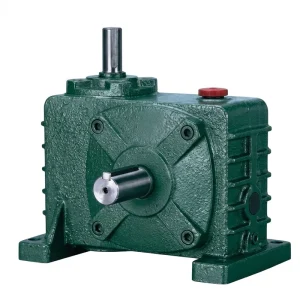
EP-WPZ 0.4–5.2 L Oil Capacity Single Speed Reducer
The EP-WPZ series is a right-angle worm واحد رفتار کم کرنے والا with factory-measured oil capacity per frame (0.4 L at size 50 through 5.2 L at size 135), which directly supports accurate thermal load management — a critical parameter when the thermal power limit, not the mechanical rating, is the binding constraint for continuous-duty applications. The oil volume on the nameplate should match the fill confirmation performed at installation.
Mounting Position Codes and Their Impact on Oil Fill Level
The mounting position field on a کیڑا کم کرنے والا گیئر باکس nameplate controls which face of the housing is the base, and therefore which fill plug position corresponds to the correct oil level. IEC 60034-7 defines standardised mounting positions using IM codes (e.g. IM B3 for horizontal base-mounted, IM V1 for vertical shaft-down). The oil fill level calibrated for an IM B3 installation — where the worm wheel dips into the sump from the side — is physically different from the fill level required for an IM V1 installation where the output shaft exits downward and the worm wheel position relative to the oil surface changes entirely.
Installing a سنگل اسپیڈ گیئر ریڈوسر in a mounting position different from the one on the nameplate without adjusting the oil fill quantity is one of the most common causes of premature worm gear failure in the field. Under-filling in a non-nameplate mounting position leaves the worm wheel tooth contact zone partially unlubricated during high-load periods; over-filling causes churning losses that raise oil temperature beyond the thermal limit. The mounting position code should be confirmed against the actual installation orientation at commissioning, and the oil volume should be adjusted to match the fill level mark on the housing face that corresponds to the installed position — not the nameplate position if they differ.
Five Nameplate Misreading Mistakes That Lead to Premature Failure
Mistake 1: Using Catalogue Torque Instead of Nameplate Torque
Catalogue pages show the rated torque for the most common ratio in the frame. If you ordered a non-standard ratio or a unit built for a different input speed, the nameplate torque may differ from the catalogue value. Always read the nameplate, not the brochure, for the unit actually installed.
Mistake 2: Ignoring the Thermal Limit When the Mechanical Rating Fits
اے ہائی ٹارک ورم گیئر باکس may carry the required output torque mechanically but exceed its thermal power limit if the application duty cycle is continuous. The thermal limit is the lower of the two constraints in most worm کیڑے کی رفتار کم کرنے والا applications above 1/30 ratio. Check both fields on the nameplate, not just the torque figure.
Mistake 3: Multiplying Service Factor Instead of Dividing
Effective usable torque = rated torque DIVIDED by service factor. Multiplying instead gives a result 56–100% larger than actual usable capacity, leading to systematic undersizing in shock-load applications — a common error seen in procurement specifications from engineering teams in Colombia and Brazil who are new to AGMA service factor conventions.
Mistake 4: Assuming the Nameplate Ratio Is the Exact Achieved Ratio
Nominal ratios are rounded design targets. The actual ratio of a worm single speed reduction gear depends on the specific tooth count selected to approximate the nominal, and may vary by 2–5% from the printed figure. For speed-critical applications such as synchronised conveyors in the Netherlands or precision positioning systems in South Korea, use the actual ratio from the engineering drawing rather than the nameplate nominal.
Mistake 5: Changing Mounting Position Without Adjusting Oil Fill
The nameplate mounting position code is tied to the oil fill volume the unit was calibrated for. Rotating the housing to a non-nameplate orientation without recalibrating the oil level is a direct path to premature worm wheel wear in the field, regardless of how well the torque and ratio match the application requirement.
Need a correctly rated unit for your application?
Browse the Single Speed Reducer Range
Find the frame, ratio, and service class that match your nameplate requirements — or contact the technical team with your application data for a confirmed specification.
Compatible Products for Complete Drive Systems
اے واحد رفتار کم کرنے والا operates as part of a broader drivetrain. The following product categories are dimensionally matched to the WP-series worm reducer platform and are available from the same production source — enabling verified system compatibility without multi-vendor interface risk.
الیکٹرک موٹرز

IEC and NEMA frame motors matched to the WP-series input bore dimensions. When pairing a motor to a worm reducer motor assembly, the motor nameplate rated power must not exceed the lower of the reducer’s mechanical and thermal power ratings. Verified motor-reducer pairings remove the ambiguity of calculating thermal load independently for each component.
ورم گیئر باکس

The full range of کیڑا گیئر ریڈوسر گیئر باکس units — from compact NMRV frames through to heavy-duty WP-series housings — shares the same material and manufacturing standard as the single speed reducer range. For applications requiring a ratio beyond the single-stage maximum of 1/60, two-stage worm gearbox units from the same platform provide dimensional continuity and common spare-parts stocking.
About This Manufacturing Facility
This production facility manufactures a broad range of power transmission products including agricultural gearboxes, کیڑا گیئر کم کرنے والے, planetary gear drives, power take-off shafts, hydraulic cylinders, gears, roller chains, and motors. The facility holds ISO 9001:2015 certification. Engineering and production cover worm gears, sprockets, pulleys, shafts, and both standard and non-standard mechanical components, with housings produced in ductile iron, cast iron, cast steel, precision cast steel, and cast aluminium depending on the application requirement. The manufacturing team has direct in-house capability across gear cutting, heat treatment, housing boring, and assembly — providing full traceability from raw material selection through to finished unit inspection and despatch.
ورک شاپ




اکثر پوچھے گئے سوالات
ایڈیٹر: PXY