
آئل پمپ موٹر
DC Motor
The definitive guide to understanding, selecting, and applying DC oil pump motors — from hydraulic power packs to vehicle lift systems and specialised industrial equipment.
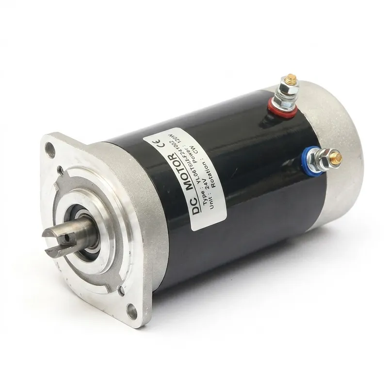
What Is an Oil Pump Motor?
An oil pump motor is a direct current electric motor specifically engineered to drive hydraulic pumps in mobile and industrial power systems. Unlike general-purpose motors, oil pump motors are built for short intermittent duty cycles at high torque output — the pattern that hydraulic pump circuits require when lifting, tilting, or pressurising a load.
These motors convert electrical energy from a battery or DC power supply into rotational mechanical energy, which is then transferred to a gear pump or piston pump. The pump converts that rotation into controlled hydraulic flow and pressure. The motor and pump together form the core of a hydraulic power unit (HPU), which is the heart of nearly every mobile vehicle lift, tail-lift gate, dock leveller, and hydraulic platform system in operation today.
Because vehicle hydraulic systems typically operate from 12V, 24V, 36V, 48V, or 72V battery banks, oil pump motors are almost universally DC machines — either wound-field or permanent-magnet types — designed to produce high starting torque and sustain it through each working cycle without overheating.
Oil Pump Motor Types
-
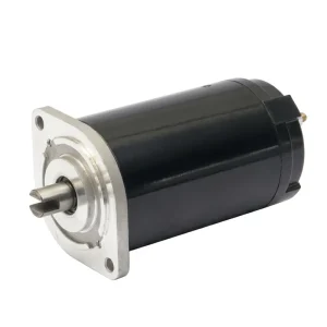
EP-XL2408FCE 800W آئل پمپ موٹر
-
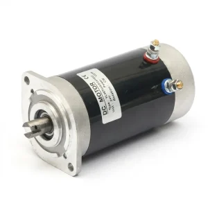
EP-XL2412FCE 1200W آئل پمپ موٹر
-
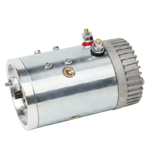
EP-XL16LTBX 1600W 12V آئل پمپ موٹر
-
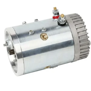
EP-XL22LTBX 2200W 24V آئل پمپ موٹر
-
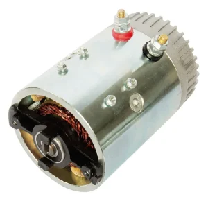
EP-XL22FD 2200W 24V آئل پمپ موٹر
-
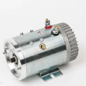
EP-XL22ZX 2200W 24V آئل پمپ موٹر
-
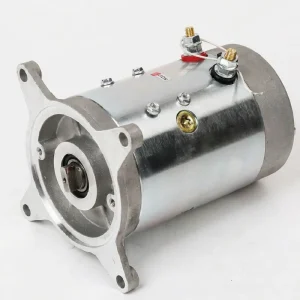
EP-XL22QL 2200W 22V آئل پمپ موٹر
-
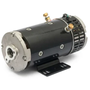
EP-XL2440NK 4000W 24V آئل پمپ موٹر
-
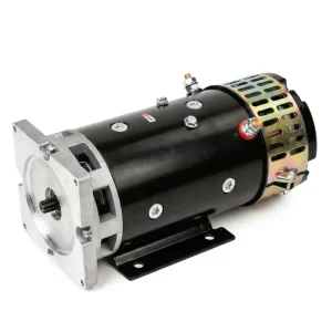
EP-XL40LT 4200W 24V آئل پمپ موٹر
-
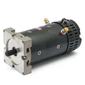
EP-XL2430TW 3000W 24V آئل پمپ موٹر
-
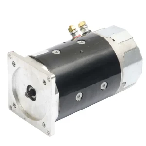
EP-XL2433PNK 4500W 24V آئل پمپ موٹر
-
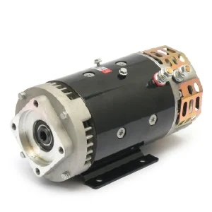
EP-XL2455ZX 5500W 24V آئل پمپ موٹر
What Makes Up an Oil Pump Motor?
Every oil pump motor shares the same core architecture. Understanding each component helps in diagnosing faults and specifying the right replacement.
Armature (Rotor)
The rotating core wound with copper coils. Current flowing through the armature windings interacts with the stator magnetic field to generate torque. The armature shaft couples directly to the pump drive gear.
Stator (Field Assembly)
The stationary outer casing that provides the magnetic field. In wound-field motors this is copper-wound field coils; in permanent-magnet (PM) motors, high-strength permanent magnets are bonded to the inside of the steel casing.
کمیوٹیٹر
A segmented copper ring on the armature shaft that mechanically switches current direction through the armature windings as the rotor turns, maintaining continuous torque in one direction. It is the defining feature of a brushed DC motor.
Carbon Brushes
Spring-loaded graphite blocks that ride against the commutator and transfer current to the rotating armature. Brushes are the primary wear component. They are replaceable and their condition directly determines motor service life.
بیرنگ
Ball or roller bearings at both ends of the armature shaft support the rotor and absorb radial and axial loads. Pre-greased sealed bearings are standard for oil pump applications where contamination resistance is critical.
End Brackets and Housing
Cast aluminium or steel end brackets locate the bearings and close the motor body. The drive-end bracket often incorporates the mounting flange and SAE pump adapter that mates directly with the hydraulic gear pump body.
Terminals and Wiring
Heavy-gauge copper terminals (A1/A2 for armature, D1/D2 for field windings on wound-field models) carry the high starting currents of up to 210A that hydraulic pump motors draw. Correct terminal polarity determines rotation direction.
Thermal Insulation System
Class F insulation (rated to 155°C) is standard across the range. The insulation system protects armature windings from heat build-up during duty cycles, ensuring safe operation and long service life under intermittent high-load conditions.
How to Choose the Right Oil Pump Motor
Select Guide
At a Glance
Step 01
Match the System Voltage
Start with the battery bank voltage of your vehicle or power unit. Available standards are 12V, 24V, 36V, 48V, and 72V. Most industrial platform equipment runs at 24V or 48V. Light-duty vehicle systems are often 12V. Mismatching voltage destroys the motor within seconds — this is the non-negotiable first filter.
Step 02
Determine Required Power and Torque
Calculate the hydraulic power demand: multiply pump displacement (cc/rev) by operating pressure (bar) by speed (rpm) and divide by 600 to get kW. Add 20-30% margin for starting torque peaks. Our range spans 800W to 4,200W, covering most mobile hydraulic applications from small tail-lifts to heavy platform loaders.
Step 03
Verify the Duty Cycle
Duty cycle specifies how long the motor can run (on-time) within a defined period (e.g., 2min-7%ED means the motor may run for 2 minutes at 7% of each hour). Under-rating the duty cycle causes premature thermal failure. Count your daily lift cycles, estimate on-time per cycle, and choose a motor whose rated ED comfortably exceeds your calculated figure.
Step 04
Choose the IP Protection Level
IP43 is adequate for enclosed indoor applications with minimal splash exposure. IP54 is required for outdoor vehicle-mounted systems, wash-down environments, or anywhere rain and debris contact is possible. The higher the second digit, the better the liquid ingress resistance. Never downgrade IP rating to save cost in outdoor-rated equipment.
Step 05
Confirm Mounting and Shaft Configuration
Oil pump motors bolt directly to the hydraulic pump. The coupling tooth count (2-tooth or 9-tooth spline) must match the pump coupling. Verify the flange bolt pattern, shaft diameter, and overall motor length against the available envelope in the power unit housing. SAE flange adapters are available for cross-brand fitment.
Also Consider
Customisation Options
Thermal protection thermistors, EMI suppression capacitors, custom shaft lengths, non-standard voltages, bi-directional rotation, special frame coatings, and continuous-duty configurations are all available. Contact our engineering team with your full system specification for a tailored solution.