
روٹری کلٹیویٹر گیئر باکس
روٹری کاشتکار گیئر باکس ٹریکٹر پر لگے روٹری ٹلر یا روٹاویٹر کا مکینیکل کور ہے۔ یہ ٹریکٹر کے PTO شافٹ کو روٹر بلیڈ اسمبلی سے جوڑتا ہے، بیک وقت ڈرائیو کے محور کو 90 ڈگری تک ری ڈائریکٹ کرتا ہے اور شافٹ کی رفتار کو بلیڈ کی بہترین کام کرنے والی رفتار سے مماثل کرتا ہے۔ اس جزو کے بغیر، انجن سے حاصل ہونے والی توانائی کو قابل استعمال شکل میں مٹی سے منسلک ٹائنوں تک نہیں پہنچایا جا سکتا۔ زرعی استعمال میں ہر ٹلر گیئر باکس اس لیے ایک مقصد کے لیے ڈیزائن کیا گیا رائٹ اینگل بیول گیئر یونٹ ہے، جو کھیت کی کاشت سے پیدا ہونے والے مسلسل ٹارک اور وقفے وقفے سے جھٹکوں کی لوڈنگ کو سنبھالنے کے لیے بنایا گیا ہے۔
اصطلاح "روٹری کلٹیویٹر گیئر باکس" پاور کلاسز کی ایک رینج پر محیط ہے - مارکیٹ کے باغات اور چھوٹی ہولڈنگز میں استعمال ہونے والے 20 HP کمپیکٹ ٹریکٹر یونٹس سے لے کر تجارتی وسیع پیمانے پر کاشت میں تعینات 125 HP ہیوی ڈیوٹی اسمبلیوں تک۔
روٹری کلٹیویٹر گیئر باکس کی اقسام
-
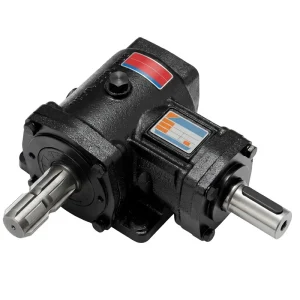
EP30 30HP 540 RPM روٹری کلٹیویٹر گیئر باکس
-
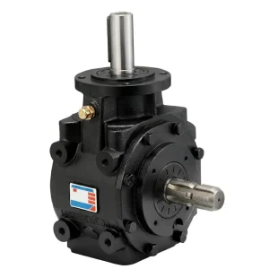
EP 1:3 تناسب 50HP 540rpm روٹری کلٹیویٹر گیئر باکس
-
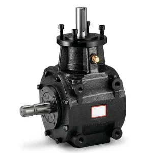
EP HC-75 سیریز 75/100/125 HP 540 RPM روٹری کلٹیویٹر گیئر باکس
-
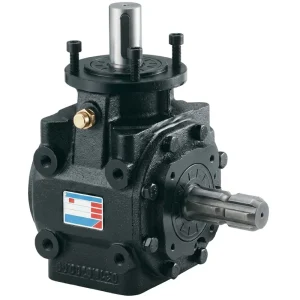
EP 1:3 تناسب 30HP 540rpm روٹری کلٹیویٹر گیئر باکس
-
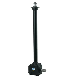
EP-1.31:1 تناسب 100HP 600rpm روٹری کلٹیویٹر گیئر باکس
-
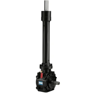
EP 1:3 تناسب 50HP 540rpm روٹری کلٹیویٹر گیئر باکس
-
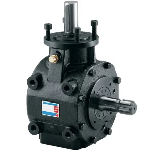
EP-1:3 تناسب 62HP 540rpm روٹری کلٹیویٹر گیئر باکس
صحیح روٹری کلٹیویٹر گیئر باکس کا انتخاب کیسے کریں۔
ٹریکٹر HP میچ کریں۔
اپنے ٹریکٹر کے PTO آؤٹ پٹ پر یا اس سے اوپر کی درجہ بندی والا زرعی ٹلر گیئر باکس منتخب کریں۔ کبھی بھی کم وضاحت نہ کریں — گیئر باکس کو اس کی ریٹیڈ پاور سے اوپر چلانے سے گیئر پہننے میں تیزی آتی ہے اور صدمے کے بوجھ کے تحت تباہ کن دانتوں کی خرابی کا خطرہ ہوتا ہے۔
پی ٹی او کی رفتار کی تصدیق کریں۔
تصدیق کریں کہ آیا آپ کا ٹریکٹر PTO 540 rpm پر چلتا ہے یا 1,000 rpm پر۔ ہماری ٹلر ڈرائیو گیئر باکس رینج کے تمام موجودہ ماڈلز کو 540 rpm ان پٹ کے لیے درجہ بندی کیا گیا ہے - اس پاور کلاس میں آلات کے لیے عالمی معیار۔
آؤٹ پٹ انٹرفیس چیک کریں۔
آؤٹ پٹ شافٹ قطر اور کنکشن کی قسم (آپٹک ایکسس یا کیڈ) کو اپنے عمل کے روٹر ہب کی تفصیلات کے خلاف تصدیق کریں۔ آؤٹ پٹ میں جہتی مماثلتیں گیئر باکس سے لاگو کرنے میں ناکام ہونے کی ایک عام وجہ ہیں۔
مٹی کی قسم پر غور کریں۔
بھاری چکنی مٹی کم تناسب (مثلاً 1:3) گیئر باکس سے فائدہ اٹھاتی ہے جو ٹائن شافٹ پر زیادہ ٹارک فراہم کرتی ہے۔ ہلکی ریتلی مٹی زیادہ روٹر کی رفتار کو قبول کر سکتی ہے۔ مٹی کی قسم کا تناسب کاشت کے معیار کو بہتر بناتا ہے اور لباس کو کم کرتا ہے۔
ISO 9001:2015 مصدقہ مینوفیکچرنگ
اپنے آپریشن کے لیے صحیح روٹری کلٹیویٹر گیئر باکس تلاش کریں۔
ہماری انجینئرنگ ٹیم آپ کے ٹریکٹر، عمل درآمد اور مٹی کے حالات کے لیے صحیح زرعی گیئر باکس کی تفصیلات کو منتخب کرنے، بیان کرنے اور اس کی تصدیق کرنے میں آپ کی مدد کرنے کے لیے تیار ہے۔ ہم OEM انضمام، براہ راست متبادل خریداری، اور بڑے حجم والے اکاؤنٹس کے لیے حسب ضرورت ترتیب کی حمایت کرتے ہیں۔
روٹری کلٹیویٹر گیئر باکس کے کلیدی اجزاء
یہ سمجھنا کہ اس قسم کا زرعی گیئر باکس کس چیز سے بنا ہے آپریٹرز کو بہتر خریداری، دیکھ بھال اور تبدیلی کے فیصلے کرنے میں مدد کرتا ہے۔ ذیل میں موجود ہر جزو اسمبلی کی مجموعی کارکردگی اور استحکام میں ایک مخصوص کردار ادا کرتا ہے۔
ہاؤسنگ / کیسنگ
ڈکٹائل آئرن (GGG-50 مساوی) یا کاسٹ ایلومینیم پاور کلاس اور ایپلی کیشن کے لحاظ سے کاسٹ کریں۔ ہاؤسنگ تمام اندرونی اجزاء کے لیے ساختی کنٹینمنٹ فراہم کرتا ہے، گیئر سینٹر کے فاصلوں اور بیئرنگ بور کی پوزیشنوں کو درست رواداری کے لیے متعین کرتا ہے، اور سخت مٹی اور سرایت شدہ ملبے سے ٹائینز کے ذریعے واپس منتقل ہونے والے صدمے کے بوجھ کو جذب کرتا ہے۔ ڈکٹائل آئرن کو زیادہ طاقت والے یونٹوں کے لیے ترجیح دی جاتی ہے۔ کاسٹ ایلومینیم لائٹر ڈیوٹی ایپلی کیشنز میں استعمال کیا جاتا ہے جہاں وزن میں کمی کو ترجیح دی جاتی ہے۔
سرپل بیول گیئر سیٹ
ڈرائیو پنین اور ڈرائیوڈ گیئر وہیل ہر دائیں زاویہ ٹیلر گیئر باکس کا دل ہیں۔ دونوں ہیٹ ٹریٹمنٹ کے بعد کیس-سخت الائے اسٹیل اور فنش گراؤنڈ سے مشینی ہوتے ہیں تاکہ DIN کوالٹی کلاس معیارات کے مطابق دانتوں کی پروفائل کی درستگی حاصل کی جا سکے۔ سرپل ٹوتھ فارم بیک وقت ایک سے زیادہ دانتوں پر بوجھ تقسیم کرتا ہے، جس سے سٹریٹ کٹ بیول متبادل کے مقابلے میں ہاؤسنگ سائز کے مقابلے میں پرسکون دوڑ، کم کمپن، اور زیادہ بوجھ کی گنجائش پیدا ہوتی ہے۔ دانتوں کی گنتی اور ماڈیول یونٹ کے گیئر تناسب اور ٹارک کی صلاحیت کا تعین کرتے ہیں۔
ان پٹ شافٹ
ان پٹ شافٹ گیئر باکس کو PTO ڈرائیو شافٹ سے جوڑتا ہے اور بیول پنین کو لے جاتا ہے۔ سب سے عام انٹرفیس ایک 1 3/8 انچ کا Z6 (چھ-اسپلائن) کنکشن ہے - تمام بڑے ٹریکٹر برانڈز اور خطوں میں 540 rpm ٹریکٹر PTO سسٹمز کے لیے قریب عالمگیر معیار۔ شافٹ کو درمیانے کاربن الائے اسٹیل سے مشینی بنایا گیا ہے، اسپلائن سیکشن کو ISO 500 یا DIN 9611 معیارات پر کاٹ دیا گیا ہے۔ موسمی استعمال کے سالوں میں تیل کی مہر کی قابل اعتماد کارکردگی کو یقینی بنانے کے لیے شافٹ سیل رابطے کی سطحیں عین قطر پر گراؤنڈ ہیں۔
آؤٹ پٹ شافٹ
آؤٹ پٹ شافٹ کارفرما بیول گیئر رکھتا ہے اور عمل کے ٹائن روٹر فلینج کو گردشی قوت فراہم کرتا ہے۔ آؤٹ پٹ شافٹ انٹرفیس ایپلی کیشن کے لحاظ سے مختلف ہوتے ہیں: ہموار آپٹک ایکسس (سلنڈریکل) شافٹ استعمال کیے جاتے ہیں جہاں حب کلیمپنگ کو ترجیح دی جاتی ہے۔ کلیدی آؤٹ پٹس استعمال کیے جاتے ہیں جہاں ایک کی وے سلاٹ روٹر ہب پر مثبت ٹارک رجسٹریشن فراہم کرتا ہے۔ متبادل گیئر باکس کو فٹ کرنے سے پہلے شافٹ کا قطر، ایکسٹینشن کی لمبائی، اور فلینج بولٹ سرکل پیٹرن سبھی کی توثیق عمل کے روٹر کی ماؤنٹنگ تفصیلات کے خلاف ہونی چاہیے۔
ٹاپرڈ رولر بیرنگ
ہیوی ڈیوٹی ٹاپرڈ رولر بیرنگ ان پٹ اور آؤٹ پٹ شافٹ دونوں پر بنیادی لوڈ پوزیشنوں پر استعمال ہوتے ہیں۔ ٹیپرڈ رولرس کو گہرے نالی والے بال بیرنگ پر منتخب کیا جاتا ہے کیونکہ وہ بیک وقت مشترکہ ریڈیل اور محوری قوتوں کو سنبھالتے ہیں - دائیں زاویہ والے بیول گیئر کے انتظامات میں ایک اہم ضرورت ہے جہاں گیئر میش الگ کرنے والی قوتیں پیدا کرتا ہے جو شافٹ کے دونوں محوروں کے ساتھ محوری طور پر کام کرتی ہے۔ پری لوڈڈ بیئرنگ انسٹالیشن شافٹ اینڈ پلے کو ختم کرتی ہے اور یونٹ کے مکمل سروس وقفہ کے دوران مسلسل گیئر میش جیومیٹری کو برقرار رکھتی ہے۔
تیل کی مہریں اور گسکیٹ
این بی آر (نائٹرائل ربڑ) ڈبل ہونٹ رابطہ مہریں ہر شافٹ پینیٹریشن پوائنٹ پر لگائی جاتی ہیں۔ اندر کی طرف بنیادی ہونٹ ہاؤسنگ کے اندر گیئر آئل کو برقرار رکھتا ہے۔ باہر کی طرف ثانوی ہونٹ مٹی کے ذرات، فصل کی باقیات، اور گیئر گہا سے نمی کو خارج کرتا ہے۔ ہاؤسنگ الگ کرنے والے چہروں کو تیل سے بچنے والے گاسکیٹ یا اینیروبک سیلنٹ کے ساتھ سیل کیا جاتا ہے، جو موسموں میں تھرمل سائیکلنگ کے دوران بھی ہاؤسنگ جوائنٹ لائن پر تیل کے رسنے کو روکتا ہے۔ مہر اور گسکیٹ کی حالت ابتدائی زرعی گیئر باکس کی ناکامی کی دیکھ بھال سے متعلق سب سے عام وجہ ہے۔ کام کرنے والے یونٹوں میں سالانہ معائنہ کی سفارش کی جاتی ہے۔
چکنا کرنے کا نظام
یہ ایگریکلچرل گیئر ڈرائیو سپلیش لبریکیشن کا استعمال کرتی ہے: گیئر آئل سیل بند ہاؤسنگ کیویٹی کے نچلے حصے کو بھرتا ہے، اور گھومنے والا گیئر سیٹ مسلسل تیل اٹھاتا ہے اور تمام دانتوں کے کنارے، بیئرنگ ریس، اور شافٹ سیل ہونٹوں میں تقسیم کرتا ہے۔ عام موسمی آپریشن کے دوران کسی بیرونی پھسلن پوائنٹس کی ضرورت نہیں ہے۔ معیاری تیل کی تصریح EP (انتہائی دباؤ) گیئر آئل، SAE 80W-90 گریڈ ہے، جو ڈِپ اسٹک یا بصری شیشے سے ظاہر کردہ سطح پر بھرا ہوا ہے۔ رن ان فیز سے دھاتی ذرات کو فلش کرنے کے لیے 50 کام کے اوقات میں تیل کی ابتدائی تبدیلی کی سفارش کی جاتی ہے۔ بعد کے وقفے عام طور پر آپریٹنگ درجہ حرارت اور لوڈ سائیکل کے لحاظ سے 200-250 گھنٹے ہوتے ہیں۔
ماؤنٹنگ فلانج اور بولٹ انٹرفیس
گیئر باکس مشینی ماؤنٹنگ فلینج کے ذریعے عمل درآمد کے فریم سے منسلک ہوتا ہے جس میں یونٹ کی پاور کلاس اور فریم ڈیزائن کے لیے مخصوص بولٹ سرکل پیٹرن ہوتا ہے۔ ماؤنٹنگ ہارڈویئر کی درست ٹارکنگ اہم ہے — انڈر ٹارک والے بولٹ گیئر باکس اور فریم کے درمیان مائیکرو موومنٹ کی اجازت دیتے ہیں جو ہاؤسنگ باس میں تھکاوٹ کے کریکنگ کو تیز کرتا ہے، جب کہ زیادہ ٹارک والے فاسٹنر کاسٹ ہاؤسنگ میں تھریڈڈ بورز کو اتار سکتے ہیں۔ ہمیشہ اسمبلی مینوئل کا حوالہ دیں یا کسی نئے یا متبادل ٹیلر گیئر باکس یونٹ کو موجودہ نافذ کرنے والے فریم میں فٹ کرتے وقت مینوفیکچرر سے صحیح ٹارک تفصیلات طلب کریں۔