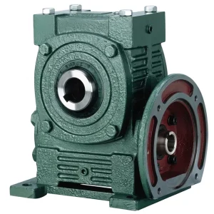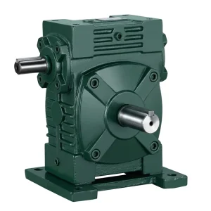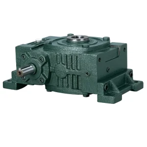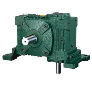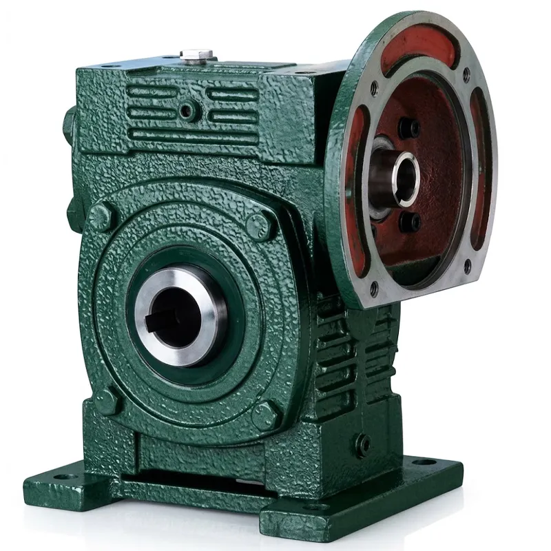
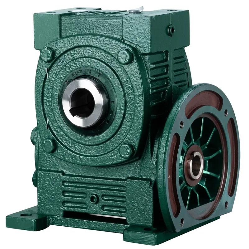
EP-WPWDKA-S 0.12–15 kW Universal Speed Reducer
The EP-WPWDKA-S Universal Speed Reducer offers versatile mounting with WPWDKA (top input) and WPWDKS (side input) configurations. Available in 11 sizes from 40 to 250, it supports input powers from 0.12 kW to 15.0 kW and reduction ratios ranging from 1/5 to 1/60. The unit features a robust cast iron housing with double output shafts for flexible installation. Key dimensions vary by model, with output shaft diameters spanning 6mm to 28mm and flange options including M8, M10, M12, and M16 bolt patterns. Weights range from 5 kg for the compact size 40 to 395 kg for the heavy-duty size 250, ensuring reliable torque transmission for diverse industrial applications requiring precise speed control.
Universal Speed Reducer Series
EP-WPWDKA-S 0.12–15 kW Universal Speed Reducer
The EP-WPWDKA-S is a heavy-duty universal speed reducer engineered for demanding industrial drive applications where reliable torque multiplication, compact installation geometry, and continuous-duty operation are non-negotiable. Based on the proven WPWDKA-S worm gear architecture, this universal speed reducer accepts input power from 0.12 kW through 15 kW across size codes 40 to 250, with reduction ratios spanning 1/5 to 1/60 — a range wide enough to match virtually any combination of motor speed and required output shaft speed in a single gearbox body. The dual hollow-bore output configuration, foot-mount baseplate, and flanged motor face make it straightforward to integrate into new equipment designs and retrofit existing drive trains without custom adapter engineering, which is why the WPWDKA-S format is one of the most widely specified کیڑا گیئر کی رفتار کم کرنے والا platforms across industrial markets in Australia, Germany, Brazil, the United Kingdom, and Southeast Asia.
Technical Specifications — WPWDKA-S Series Universal Speed Reducer
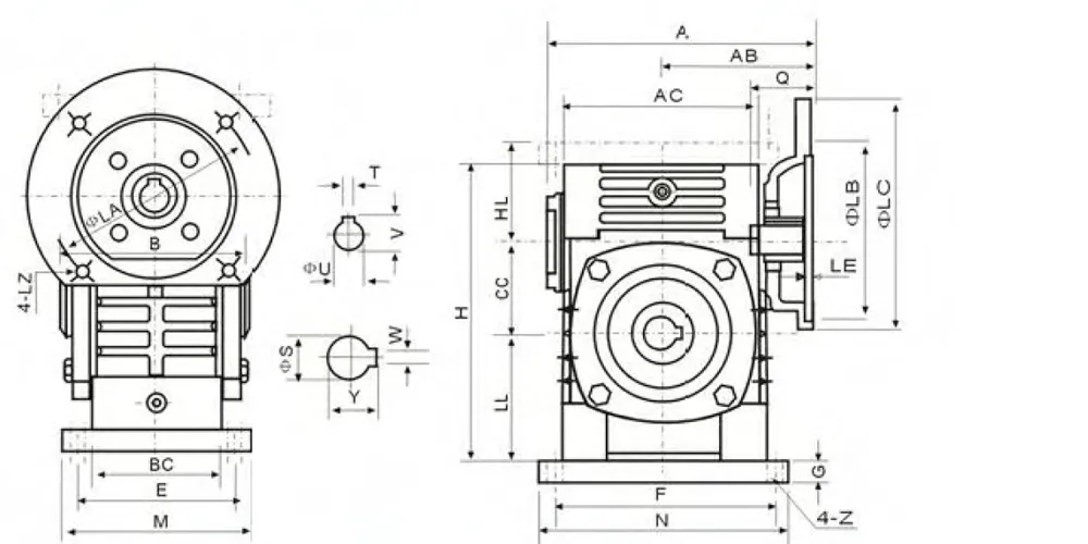
All dimensional data below is extracted from the WPWDKA-S Universal Speed Reducer engineering drawing. Dimensions are in millimetres; weight in kilograms. For specific reduction ratio availability per size, refer to the selection note below the table.
| سائز | kW | تناسب | اے | اے بی | بی | ایچ | ایم | ن | ایل اے | ایل بی | ایل سی | ایل زیڈ | سوال | یو | T×V | ایس | W×Y | kg |
|---|---|---|---|---|---|---|---|---|---|---|---|---|---|---|---|---|---|---|
| 40 | 0.12 | 1/5–1/60 | 135 | 75 | 85 | 135 | 130 | 80 | 115 | 95 | 140 | M8 | 31 | 11 | 4×12.8 | 16 | 6×18.8 | 5 |
| 50 | 0.18 | 1/5–1/60 | 151 | 83 | 105 | 165 | 120 | 95 | 115 | 95 | 140 | M8 | 31 | 11 | 4×12.8 | 20 | 6×22.8 | 8 |
| 60 | 0.37 | 1/5–1/60 | 167 | 91 | 110 | 195 | 150 | 105 | 130 | 110 | 160 | M8 | 33 | 14 | 5×16.3 | 25 | 8×28.3 | 12.5 |
| 70 | 0.37–0.75 | 1/5–1/10 | 200–202 | 109–111 | 130 | 233 | 150 | 115 | 130–165 | 110–130 | 160–200 | M8–M10 | 40–42 | 14–19 | 5×16.3 / 6×21.8 | 30 | 8×33.3 | 17 |
| 80 | 0.75–1.5 | 1/15 | 225 | 125 | 150 | 268 | 170 | 135 | 165 | 130 | 200 | ایم 10 | 48–52 | 19–24 | 6×21.8 / 8×27.3 | 35 | 10×38.3 | 26 |
| 100 | 1.5 | 1/20 | 280 | 148 | 160 | 330 | 190 | 155 | 165 | 130 | 200 | ایم 10 | 52 | 24 | 8×27.3 | 40 | 12×43.3 | 41.5 |
| 120 | 2.2–3.0 | 1/25 | 333 | 181 | 175 | 395 | 230 | 180 | 215 | 180 | 250 | ایم 12 | 63 | 28 | 8×31.3 | 45 | 14×48.8 | 60 |
| 135 | 3.0–4.0 | 1/30–1/40 | 375 | 202 | 210 | 455 | 250 | 200 | 215 | 180 | 250 | ایم 12 | 63 | 28 | 8×31.3 | 60 | 18×64.4 | 90 |
| 155 | 5.5 | 1/50 | 448 | 247 | 256 | 493 | 290 | 220 | 265 | 230 | 300 | ایم 12 | 83 | 38 | 10×41.3 | 70 | 20×74.9 | 118 |
| 175 | 5.5–7.5 | 1/60 | 481 | 262 | 282 | 558 | 310 | 250 | 265 | 230 | 300 | ایم 12 | 83 | 38 | 10×41.3 | 80 | 22×85.4 | 167 |
| 200 | 11.0 | 1/5–1/60 | 543 | 285 | 320 | 620 | 355 | 290 | 300 | 250 | 350 | ایم 16 | 114 | 42 | 12×45.3 | 85 | 22×90.4 | 237 |
| 250 | 11.0–15.0 | 1/5–1/60 | 615 | 330 | 400 | 750 | 450 | 380 | 300 | 250 | 350 | ایم 16 | 114 | 42 | 12×45.3 | 110 | 28×116.4 | 395 |
All dimensions in mm. Weight in kg. Reduction ratios and motor flange dimensions vary by power sub-variant — consult the full selection table for exact ratio/size combinations.
Five Core Advantages of the EP-WPWDKA-S
01 — Wide Power Range from 0.12 kW to 15 kW
Twelve size codes — 40 through 250 — cover input power from 0.12 kW up to 15 kW within a single product family that shares the same dimensional interface standards and mounting geometry. This means a production engineer can specify a size-40 unit for a light-duty conveyor drive and a size-250 unit for a heavy mixer drive within the same project, sourcing both from a single supplier with consistent documentation, interchangeable installation interfaces, and a uniform spare-parts ecosystem. No other universal speed reducer configuration requires separate product families for different power ranges.
02 — Dual Hollow-Bore Output for Shaft-Mounting Flexibility
The WPWDKA-S universal speed reducer configuration provides hollow output bores on both sides of the output shaft (dual hollow output), allowing the driven machine shaft to be inserted from either side of the gearbox. This double-ended hollow bore eliminates the need for flexible couplings in many direct shaft-mount installations, reduces the overall drive train length, and gives machine designers the option to connect the load from whichever side suits the equipment layout — a significant advantage in space-constrained installations common in packaging machinery, food processing equipment, and agricultural drive trains in the UK, Germany, and Australia.
03 — Reduction Ratios from 1/5 to 1/60 in a Single Unit
Gear reduction ratios of 1/5, 1/10, 1/15, 1/20, 1/25, 1/30, 1/40, 1/50, and 1/60 are available within the same WPWDKA-S housing series, giving system designers the flexibility to match output speed precisely to application requirements without multi-stage gearing. The worm gear reduction ratio range covers slow-speed, high-torque applications — agitator drives, conveyor head drums, screw feeders — as well as moderate reduction applications where speed regulation rather than maximum torque multiplication is the primary requirement. Single-stage worm reduction to 1/60 is a significant efficiency advantage over multi-stage systems that accumulate bearing losses across multiple mesh points.
04 — Cast Iron Housing with Integral Foot Mount and Flange
The WPWDKA-S universal speed reducer housing is cast from high-grade grey cast iron, machined on CNC centres to the dimensional tolerances that flange-mount motor interfaces and foot-mount baseplates require for precise alignment. The integral foot mount — four-bolt pattern with tapped baseplate holes — allows direct floor or frame mounting without external brackets. The motor input flange accepts standard IEC or NEMA frame motors directly, eliminating adapter plates in most installations. This combination of foot mount, motor flange, and dual hollow output in a single casting reduces the number of separate components in the drive train and the alignment steps required during installation — a practical time saving that facilities maintenance teams in Singapore and South Korea consistently identify as a key procurement consideration.
05 — ISO 9001:2015 Certified Manufacturing with Global Distribution
Every EP-WPWDKA-S unit is produced in an ISO 9001:2015 certified manufacturing facility using CNC precision machining centres for housing bores and shaft journals, hobbing machines for worm wheel tooth profiles, and automated gear measurement systems for quality verification before assembly. This certification and production discipline ensures that dimensional tolerances, surface finish, and assembly clearances are consistent across production batches — which matters when a maintenance team in Brazil or Germany needs a replacement unit to fit exactly the same as the original without shimming or rework. Factory-direct supply through our international distribution network provides documented lead times, consistent part numbering, and technical data sheets in English for all markets.
How the Universal Speed Reducer Works
The EP-WPWDKA-S universal speed reducer operates on the worm-and-wheel principle: a hardened steel worm shaft — the input member — meshes at 90° with a bronze or alloy worm wheel — the output member. The worm shaft is connected directly to the motor through the flanged input face and is supported by precision taper roller or deep groove ball bearings at both ends. As the worm rotates, the helical thread of the worm engages successive teeth on the worm wheel, advancing the wheel by one tooth per worm revolution at the lowest reduction ratio configurations, producing the gear reduction effect. Output is taken from the worm wheel shaft, which exits the housing through hollow bores on both sides for direct shaft-mount connection to the driven equipment.
The geometry of the worm-and-wheel mesh is inherently self-locking at higher reduction ratios — when the reduction ratio exceeds approximately 1/30, the lead angle of the worm thread becomes shallow enough that the worm wheel cannot back-drive the worm, providing a natural static holding function. This self-locking characteristic makes the WPWDKA-S worm drive reducer suitable for vertically-loaded applications — hoists, lifting tables, tilting platforms — where a secondary brake would otherwise be required to prevent back-driving when the motor is de-energised. At lower reduction ratios (1/5 through 1/20), the worm lead angle is steeper and back-driving is possible, which should be considered in the application design.
The worm wheel in the WPWDKA-S is typically manufactured from centrifugally cast phosphor bronze (C93200 or equivalent) for sizes 40 through 135, where the worm-to-wheel sliding velocity and contact stress are within the bronze alloy's operating range. For larger sizes (155 through 250), the worm wheel may use a cast alloy steel centre hub with a bronze rim ring, providing the torsional strength needed to transmit 11–15 kW through the wheel hub without plastic deformation while retaining the lubrication and anti-galling properties of the bronze tooth flank at the mesh contact. The worm shaft is case-hardened alloy steel — typically 20CrMnTi or 20Cr — ground to the tooth profile tolerance and surface finish that determine mesh efficiency and service life. Internal lubrication is splash-fed from the oil sump in the housing base, with the worm rotating through the oil level to distribute lubricant across the mesh and bearings.
Materials & Construction of Universal Speed Reducer
The housing of the EP-WPWDKA-S universal speed reducer is cast from grey cast iron (GG25 or HT250 equivalent), selected for its damping properties, machinability, and compressive strength — characteristics that the bearing housings and mounting bosses of a foot-mount کیڑا گیئر کم کرنے والا require to maintain alignment under sustained radial and axial load. Housing bores are machined to H7 tolerance, providing the precise fit needed for press-fitted bearing outer races without the bore-to-bore positional error that would misalign the worm and wheel mesh. External surfaces are shot-blasted and coated in an oil-resistant primer and topcoat for corrosion protection in outdoor and humid industrial environments — relevant for agricultural and food processing applications in Australia and Brazil where equipment may be exposed to wash-down conditions.
The worm shaft is manufactured from alloy steel (20CrMnTi or equivalent) and case-hardened to 58–62 HRC at the tooth flanks, with a ground tooth profile to DIN 3974 accuracy class 7 or better. The core of the worm shaft retains a toughness of approximately 35–45 HRC, providing the fatigue resistance needed for the bending loads at the worm tooth root during full-load operation. Worm wheel blanks for sizes 40–135 are centrifugally cast from phosphor bronze (PB2 or C93200), which provides excellent sliding wear resistance at the worm-to-wheel contact under boundary lubrication conditions — the regime that the worm gear mesh operates in during start-up and at low speeds. For sizes 155–250, the worm wheel uses a cast steel hub with a bronze rim ring, combining the torsional capacity of steel with the tribological properties of bronze at the contact surface.
Bearings are taper roller or angular contact ball bearings at both worm shaft positions, selected for their combined radial and axial load capacity. The worm shaft in a high torque worm gearbox generates significant axial thrust as a reaction to the helical tooth load, and only bearings rated for combined loading should be used in the worm shaft positions — a detail that distinguishes correctly engineered worm gear reducer gearbox assemblies from lower-cost alternatives that use radial-only bearings and experience premature shaft displacement and mesh wear. Output shaft bearings are sized for the full rated output torque at the minimum reduction ratio, which represents the worst-case radial load at the output shaft bearing positions.
Universal Speed Reducer Application Scenarios
The EP-WPWDKA-S universal speed reducer is deployed across a broad range of industries where controlled speed reduction, high output torque, and a compact right-angle drive geometry are required. The following scenarios represent the primary use cases where the WPWDKA-S format is routinely specified.
Conveyor & Material Handling Systems
Belt conveyors, chain conveyors, and screw conveyors in food processing, mining, and logistics facilities use the WPWDKA-S universal speed reducer as the head-drum drive or intermediate drive unit. The self-locking characteristic at 1/30 and higher ratios prevents the loaded conveyor from back-driving when the motor is stopped — eliminating the need for a separate brake in many inclined conveyor designs. The dual hollow output bore allows a standard conveyor drive shaft to be inserted directly through the gearbox without coupling alignment, reducing installation time significantly for facilities in Australia and Germany that operate multiple conveyor lines.
Agitator & Mixer Drives
Chemical reactors, paint mixers, and wastewater treatment agitators require slow, high-torque drives that operate continuously under varying viscosity loads. The WPWDKA-S universal speed reducer at 1/40 to 1/60 ratios provides the low output speeds — typically 24–36 RPM at 1,450 RPM motor input — needed for process mixing applications without the size and cost of multi-stage reduction systems. The foot-mount baseplate allows direct floor mounting of the gearbox with the agitator shaft inserted vertically through the hollow output bore, which is the standard installation geometry for top-entry agitators in tanks and vessels across the chemical and food processing sectors in Brazil, the UK, and South Korea.
زرعی مشینری
Grain augers, seed drills, fertiliser spreaders, and irrigation pivot drives use the WPWDKA-S as the main drive gearbox, taking power from an electric motor or hydraulic motor and reducing it to the slow rotational speeds needed for each implement's function. The cast iron housing withstands the vibration and shock loading characteristic of agricultural environments, and the splash lubrication system functions correctly across the range of operating angles encountered when equipment is used on uneven terrain. Agricultural machinery producers in Australia, Brazil, and Germany regularly specify the WPWDKA-S as a replacement universal speed reducer compatible with the dimensional interface of previously installed units from multiple sources.
پیکیجنگ مشینری
Rotary filling stations, capping machines, label applicators, and cartoning equipment use compact worm drive reducers to synchronise individual station drives with the main machine timing. The WPWDKA-S universal speed reducer at size 40–80 covers the lower power requirements of individual packaging machine stations without adding excessive weight or footprint to the machine frame. Its right-angle geometry allows the motor to be positioned parallel to the machine frame rather than extending outward axially, a layout preference in the compact packaging machine designs prevalent across the Singapore, UK, and Australian food and beverage packaging sectors.
Lifting & Positioning Equipment
Scissor lifts, tilting platforms, loading dock levellers, and industrial positioners use the WPWDKA-S universal speed reducer for its natural self-locking characteristic at high reduction ratios — preventing load back-driving without a secondary braking device. The combination of M12–M16 output bore keyway dimensions in the larger sizes and the high output torque capacity supports the heavy load requirements of lifting applications in general manufacturing and warehouse facilities across Germany and Brazil where compliance with EN 14492 and local lifting equipment standards requires reliable holding under load.
Gate, Valve & Actuator Drives
Sluice gates, butterfly valves, and industrial actuator mechanisms use the WPWDKA-S universal speed reducer as the primary drive element because the self-locking worm prevents the gate or valve from being back-driven by fluid pressure when the motor is de-energised. This eliminates the need for a solenoid brake in many valve drive designs. Water treatment facilities in Australia and the UK, and irrigation system operators in Brazil, specify the WPWDKA-S as a durable, low-maintenance worm drive speed reducer for outdoor valve drive installations where ingress protection and corrosion resistance are primary selection criteria alongside the functional self-locking requirement.
مینوفیکچرر کے بارے میں
With more than a decade of dedicated engineering and manufacturing experience in mechanical power transmission, our production facility designs and builds a comprehensive range of drive components — agricultural gearboxes, کیڑا گیئر کم کرنے والا assemblies, planetary gear drives, power take-off shafts, hydraulic cylinders, gears, sprockets, pulleys, and a full spectrum of standard and non-standard machined components. Our manufacturing operation runs CNC machining centres, hobbing machines, gear grinding equipment, and automated inspection systems, producing parts in ductile iron, cast iron, cast steel, precision cast steel, and cast aluminium to the tolerances that precision mechanical drive applications demand.
Our facility holds ISO 9001:2015 certification across all production processes — from raw material receipt through machining, assembly, inspection, and shipment. Every universal speed reducer leaves our production floor with a documented quality record covering housing bore dimensions, gear mesh measurements, bearing fit checks, and assembly torque values. This traceability gives procurement engineers and maintenance managers in Germany, Australia, the UK, South Korea, Brazil, and Singapore the confidence that what arrives on-site matches the specification ordered, consistently across deliveries.
We support international customers directly through our distribution network — providing English-language technical data sheets, dimensional drawings, installation guides, and responsive engineering support for specification queries. As a factory-direct supplier of worm gear reducer manufacturers-class product, we eliminate the margin and lead-time overhead of multi-tier distribution for customers who need reliable supply of mechanical drive components at competitive terms.
ورک شاپ





Compatible & Related Products
The EP-WPWDKA-S universal speed reducer is part of a complete mechanical drive ecosystem. We manufacture and supply the following products as direct complements to the universal speed reducer — sourcing both from the same factory guarantees dimensional compatibility, consistent quality standards, and simplified technical support across your entire drive system.
We supply IEC and NEMA frame electric motors in the power range that matches every size code in the WPWDKA-S series — from 0.12 kW through 15 kW — with output shaft dimensions and mounting flanges verified to fit the motor input face of the corresponding gearbox size directly. Sourcing the motor and gearbox as a matched set eliminates the adaptation engineering that mismatched motor-gearbox combinations require, and ensures that the torque and speed ratings are correctly aligned for the application without derating calculations.

Beyond the WPWDKA-S, our کیڑا گیئر کم کرنے والا product range includes NMRV aluminium alloy worm gearboxes (size 025–150), WP cast iron worm gearboxes, and speciality configurations including flange-mount, shaft-mount, and hollow-bore output variants in both single and double reduction arrangements. The full series covers output torques from a few Newton-metres in the NMRV-25 up to several thousand Newton-metres in the WP-250 range, giving procurement engineers a single supplier for all worm reduction requirements across a facility regardless of size or power.

اکثر پوچھے گئے سوالات
How does a worm gear reducer work and why does the 90-degree shaft angle make it useful for industrial conveyor applications in Australia?
اے کیڑا گیئر کم کرنے والا works by meshing a helical worm shaft with a worm wheel whose axis is perpendicular to the worm shaft — producing a 90° change of shaft direction and a speed reduction determined by the ratio of the number of worm wheel teeth to the number of worm thread starts. In industrial conveyor applications in Australia, this right-angle geometry allows the drive motor to be positioned parallel to the conveyor frame rather than in line with the head drum shaft, which reduces the overall drive train length and keeps the motor within the conveyor footprint rather than extending beyond it. For space-constrained conveyor installations in warehouses and processing facilities, the compact right-angle format of the WPWDKA-S universal speed reducer is the primary reason it is specified over in-line helical reducers.
Do worm gears reduce speed automatically and does the WPWDKA-S universal speed reducer hold a load without a brake when the motor is switched off?
Yes — worm gears reduce speed as a direct function of the worm-to-wheel tooth ratio: input speed divided by the reduction ratio gives output speed. Regarding holding under load: the WPWDKA-S is self-locking at reduction ratios of 1/30 and above. At these ratios, the worm thread lead angle is shallow enough that the friction force at the worm-to-wheel contact exceeds the back-driving thrust from the output load, preventing the wheel from rotating the worm backward when the motor is de-energised. This natural self-locking eliminates the need for a motor brake in applications such as valve drives, tilting platforms, and inclined conveyors at these reduction ratios.
What is the purpose of a universal speed reducer and which WPWDKA-S size should I select for a 3 kW agitator drive running at 30 RPM output in a German chemical plant?
The purpose of a universal speed reducer is to convert the high rotational speed and low torque of a standard electric motor into a lower rotational speed with correspondingly higher torque, matching the motor output to the speed and torque requirements of the driven equipment. For a 3 kW agitator drive at 30 RPM output in a German chemical plant, starting from a standard 4-pole motor at 1,450 RPM: the required reduction ratio is 1,450 ÷ 30 = approximately 1/48, which falls within the 1/50 ratio option. The required gearbox is size 120 (rated at 2.2–3.0 kW input at this ratio) or size 135 (rated at 3.0–4.0 kW). Size 120 is the economical choice if the 3 kW motor is the actual continuous load; size 135 provides a safety margin for start-up torque demands and viscosity variation typical in chemical mixing applications. Both sizes are available in 1/50 ratio within the WPWDKA-S series.
Where can I find a universal speed reducer for sale with technical documentation and direct factory support available for agricultural equipment manufacturers in Brazil?
Our factory supplies the EP-WPWDKA-S universal speed reducer direct to agricultural equipment manufacturers in Brazil with full technical documentation in English — including dimensional drawings, selection tables, installation guides, and lubrication specifications. Factory-direct supply eliminates the multi-tier distribution markup that Brazilian agricultural machinery producers typically encounter when sourcing worm gear reducer manufacturers-class product through distributors, and provides direct access to our engineering team for application-specific configuration questions including non-standard reduction ratios, special shaft keyway dimensions, or modified mounting configurations required by OEM equipment designs. Lead times and current stock availability can be confirmed by contacting our sales team with the size code, ratio, and power requirements for your application.
How should I install and lubricate a worm gear reducer installation to maximise service life in a high-ambient-temperature environment like a South Korean steel processing facility?
درست worm gear reducer installation requires four steps: first, verify that the mounting surface is flat to within 0.1 mm across the foot mount footprint before bolting down — shimming is preferable to deforming the cast iron housing. Second, fill the oil sump to the correct level for the mounting orientation — the WPWDKA-S has oil level plugs for horizontal foot-mount and alternative mounting positions; incorrect oil level is the leading cause of premature bearing and mesh failure. Third, select the correct viscosity lubricant for ambient temperature: in a high-ambient South Korean steel facility where gearbox oil sump temperatures may reach 70–80°C in summer operation, ISO VG 220 or VG 320 mineral oil is appropriate; at lower ambients, VG 150 may be specified. Fourth, check for correct mesh contact pattern through the inspection cover after a 100-hour break-in period and adjust output shaft alignment if the contact pattern is not centred on the worm wheel tooth face. Adhering to these steps will maximise the service life of the heavy duty worm drive gearbox in high-temperature industrial environments.
What is the difference between a WPWDKA and WPWDKS universal speed reducer and which configuration is better for a shaft-mount drive on a packaging line in the United Kingdom?
The WPWDKA and WPWDKS universal speed reducer designations refer to different output shaft configurations within the same WP worm gearbox housing series. The WPWDKA universal speed reducer has a dual hollow output bore on both sides of the output shaft — the driven machine shaft inserts through the gearbox from either side. The WPWDKS universal speed reducer has a flanged output on one side for direct flange mounting to the driven machine rather than a hollow bore shaft-through connection. For a shaft-mount drive on a UK packaging line where the driven machine shaft is fixed and the gearbox must slide onto it from outside, the WPWDKA configuration is the correct choice — the dual hollow bore accepts the machine shaft from either side and is retained with a keyway and setscrew rather than requiring the shaft to be disconnected for gearbox installation or removal. The WPWDKS universal speed reducer flange configuration suits applications where the gearbox is mounted to a structural flange and the output connects to a coupling rather than directly to a machine shaft.
ایڈیٹر: PXY