
General Buyer Guides & Comparison
A practical installation reference for technicians and plant engineers commissioning 단일 속도 감속기 units — covering shaft alignment tolerances, coupling type selection, fastener installation torque, oil fill procedure, and the checks that should be completed before first start to prevent premature failure from installation error rather than operating overload.
Why Installation Quality Determines Service Life More Than Specification Quality
A correctly specified 단일 속도 감속기 — matched to the application torque, service factor, and thermal power limit — can fail in weeks rather than years if installed with accumulated shaft misalignment, an incorrect coupling type, or mounting bolts tightened to random torque values. Field experience with worm 단일 속도 기어 감속기 units consistently shows that the majority of in-service failures occurring in the first 500–2,000 operating hours are attributable to installation error rather than specification error or material defect. Misalignment-induced bearing overload, coupling backlash shock transmission, and bolt loosening under vibration are the three leading installation-origin failure modes, and all three are preventable with the correct installation procedures applied systematically before the unit is energised for the first time.
This guide addresses the installation of WP-series worm 단일 단계 감속기 units — including foot-mounted, flange-mounted, and combined foot-flange configurations — in industrial and agricultural applications across Australia, Canada, the UK, South Korea, Brazil, and the Netherlands. While the mechanical principles apply broadly across gear architectures, the specific alignment tolerances, coupling recommendations, and mounting torque values referenced here are appropriate to the cast iron housing and bronze worm wheel construction of the standard WP-series 웜 기어 감속기 설치 platform.
Pre-Installation Verification Checks
Before mounting a 단일 속도 감속기, four verification checks should be completed against the unit’s documentation. Skipping any of these is a common source of commissioning delays and early failures that could have been identified with 10–15 minutes of systematic checking before installation began.
Check 1: Nameplate vs. Specification
Confirm the unit nameplate ratio, service factor, and mounting position code match the specification. A unit incorrectly substituted during procurement with a different ratio or a different mounting position code will operate incorrectly from day one — the ratio mismatch produces wrong output speed, while the mounting position mismatch produces incorrect oil sump orientation relative to the worm wheel contact zone.
Check 2: Oil Fill Level
Confirm that the housing oil level is at the correct fill mark for the planned installation orientation. Units shipped with a factory oil fill are filled to the horizontal mounting fill mark by default. If the planned installation is in a different orientation — vertical output shaft-up, shaft-down, or sideways input — the oil must be adjusted to the fill mark for that orientation before installation and before first start. Running in the wrong oil level at any mounting position causes either oil starvation of the worm wheel contact or churning losses from excess oil, both of which damage the unit.
Check 3: Shaft Dimensions
Measure the actual input bore diameter (HS/U) and output shaft diameter (S) against the engineering drawing values. Verify the keyway dimensions (T×V for input, W×Y for output) match the coupling or driven load shaft. Dimensional errors in input bore sizing are more common in replacement purchases than in initial builds, particularly when sourcing a 단일 속도 감속기 as a substitute unit during emergency maintenance.
Check 4: Vent Plug
Confirm the vent plug is installed and open — not blocked by transit packaging, shipping tape, or a solid plug used for transport. A closed vent plug during operation allows pressure build-up within the housing that forces oil past the shaft seals. On WP-series housings, the vent plug is typically located on the top face; it must be opened before the unit is energised regardless of mounting orientation.

Shaft Alignment: Tolerances and Method for Worm Gear Reducer Installations
Shaft misalignment is the single most consequential installation error for a 웜 기어 감속기 coupled to a motor through a shaft coupling. Two forms of misalignment exist simultaneously in any real installation: angular misalignment, where the two shaft centrelines point in different directions rather than running parallel; and parallel (offset) misalignment, where the shaft centrelines are parallel but displaced laterally. Both impose cyclical bending loads on the coupling and on the shaft bearings at a frequency equal to the shaft rotation speed, producing fatigue loading that adds to the gear mesh and bearing loads the unit was designed and rated to carry. Beyond a threshold misalignment level, the combined fatigue loading from both gear mesh and misalignment shortens bearing life more rapidly than any other single variable in the installation.
For a 단일 속도 웜 기어 감속기 with a flexible jaw coupling or tyre-type coupling on the input shaft, the alignment tolerances that prevent premature bearing fatigue at the input shaft are typically: angular misalignment not exceeding 0.5° (approximately 0.87 mm per 100 mm of shaft length), and parallel offset misalignment not exceeding 0.1–0.3 mm depending on coupling size. These values assume a correctly selected flexible coupling with sufficient misalignment capacity for the installation; a rigid coupling requires near-perfect alignment within ±0.05 mm to function without generating misalignment loads. For the output shaft coupled to the driven load, the same tolerances apply — and are particularly important for 웜 기어 감속기 설치 on conveyor drives in Australia or mining equipment in South Africa where foundations settle during the first operating season, requiring periodic re-alignment checks.
| Alignment Check | Method | Acceptable Tolerance (Flexible Coupling) | Acceptable Tolerance (Rigid Coupling) |
|---|---|---|---|
| Angular misalignment | Dial indicator on coupling face | ≤ 0.5° (≤ 0.87 mm/100 mm) | ≤ 0.05 mm total indicator runout |
| Parallel (offset) misalignment | Straight edge or dial indicator on coupling OD | ≤ 0.1 – 0.3 mm | ≤ 0.05 mm |
| Axial separation (end float) | Feeler gauge between coupling halves | Per coupling manufacturer specification | 0 mm — flanges must contact |
| Output shaft runout (key-coupled load) | Dial indicator on driven shaft | ≤ 0.05 mm total indicator runout | ≤ 0.02 mm total indicator runout |
Coupling Selection for Single Speed Reducer Installations
Coupling selection for a 단일 속도 감속기 motor interface is not simply a matter of matching bore diameter and hub length. The coupling type determines how misalignment loads are transmitted — or absorbed — between the motor shaft and the gearbox input bore, and whether shock loads from motor starts or driven-load jams are attenuated before reaching the gear mesh or transmitted directly into the worm shaft bearings. Three coupling types account for the majority of WP-series 단일 속도 웜 기어 감속기 installations, each with distinct advantages and limitations that make them appropriate for specific application conditions.
Jaw Coupling (Spider / Elastomeric Insert)
Recommended for: Standard industrial motor-reducer connections at input power up to approximately 15 kW with moderate shock loading.
The elastomeric spider insert absorbs torsional vibration and attenuates shock transmission from motor starts. Angular misalignment capacity of 0.5–1° and parallel offset capacity of 0.1–0.5 mm accommodates the minor alignment imperfections common in field installations without imposing significant bearing loads. Insert material selection — standard polyurethane for most industrial applications, Hytrel for high-temperature environments, and bronze for fail-safe requirements — should match the operating temperature range of the 단일 속도 기어 감속기 installation.
Tyre (Donut / Flexible Tyre) Coupling
Recommended for: Higher-misalignment installations, shock-load applications, and agricultural machinery in Brazil or Colombia where foundation settlement produces ongoing misalignment.
The rubber tyre element tolerates angular misalignments up to 1–3° and parallel offsets up to 1–3 mm depending on element size — significantly more than jaw couplings. This higher misalignment capacity is particularly useful for 웜 기어 감속기 installations on equipment mounted on non-rigid bases or outdoor concrete pads that settle seasonally. The tyre element also provides excellent torsional shock absorption, making this coupling the preferred choice for bucket elevator drives, crusher-feed conveyors, and other applications with high starting torque spikes.
Rigid Coupling (Flanged or Sleeve)
Recommended for: Direct motor-flange mount (WPDKA, WPDKS series) where the motor and gearbox share a common flanged rabbet interface.
A rigid coupling or direct flange-mount interface transmits all misalignment directly into the bearings — which is why it requires near-perfect alignment (within ±0.05 mm). On the WPDKA and WPDKS flange-mount variants of the single stage right-angle worm-gear speed reducer family, the motor bolts directly to the precision-machined housing flange, and the motor shaft inserts into the input bore without a coupling element. The rabbet fit of the flange ensures alignment is determined by machining accuracy rather than field shimming, which is why flange-mount installations are often easier to align correctly than base-plate coupled units with independent motor and gearbox feet.
Manufacturing Structure & Material System — Dimensions That Drive Installation Decisions
Correct installation of a 단일 속도 감속기 requires a working knowledge of the unit’s dimensional design — specifically the shaft interface dimensions and housing mounting geometry that determine coupling bore requirements, base plate bolt-hole layout, and overhung load rating. The WP-series product family uses a consistent dimensional approach across its range that directly informs several installation decisions.
Input Bore (HS / U / T×V)
The input bore receives the motor shaft or input coupling hub. HS is the bore depth; U is the bore diameter; T×V is the keyway width × height. Coupling hub bore must match U within H7/h6 tolerance for a standard key-drive fit. An interference fit (press-on hub) requires heating or hydraulic pressing to install; a clearance fit (push-on) uses a key and set-screw. For the WP-series, most frame sizes use a clearance-to-transition fit on the coupling hub — confirm the fit class against the application vibration and reversing requirements before selecting the hub installation method.
Output Shaft (LS / S / W×Y)
LS is the output shaft protrusion length; S is the shaft diameter; W×Y is the keyway dimensions. The overhung load rating of the output shaft — how much radial force the shaft bearings can sustain from a belt, chain, or gear drive applied at a distance from the housing face — is the critical dimension for drives with external power transmission on the output. This rating should be checked against the calculated belt pull or chain tension of the driven load, particularly for high torque worm gearbox applications where large sprocket diameters are used to achieve the required chain speed.
Base Mounting (4-φZ Bolt Pattern)
The 4-φZ bolt hole pattern on the housing base must be matched to the base plate or machine frame using bolts of the correct grade and thread specification. Grade 8.8 metric bolts are standard for WP-series foot-mount installations; higher grades offer diminishing benefit because the limiting factor is typically the cast iron thread insert strength rather than the bolt itself. All four mounting bolts must reach the same torque value — an unevenly torqued base warps the housing under tension, shifting the worm shaft-to-wheel axis geometry and reducing gear mesh efficiency.
Housing Material — HT250 Cast Iron
Cast iron housing provides good vibration damping and allows precision bore machining for worm shaft alignment. It is also notch-sensitive under bending loads — which means torquing mounting bolts beyond the specified value can initiate micro-cracking at the bolt boss, not always visible externally. Using a calibrated torque wrench and the manufacturer’s specified torque value is essential, particularly for 단일 속도 감속기 units mounted on vibrating machinery where bolt loosening under vibration is a recurring concern.
Related Product
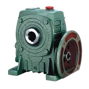
EP-WPDKA 5–350 kg Single Speed Reducer
The EP-WPDKA is a combined foot-and-flange-mount 단일 속도 감속기 that integrates a motor flange interface with a base-mounting footprint in one housing. This dual-mount configuration makes the WPDKA particularly relevant to the installation considerations in this guide: the motor flange interface (LB/LC/LA bolt pattern) eliminates the need for a coupling and base-plate motor mounting while the foot-mount allows the gearbox to be rigidly secured to the machine frame. Understanding the dimensional relationship between the motor flange, the housing base, and the output shaft is essential for correct installation of this series, as the three reference planes interact to determine the final output shaft position relative to the driven load.
Mounting Bolt Installation Torque: Values and Tightening Sequence
Mounting bolt torque is one of the most consistently neglected aspects of 단일 속도 감속기 installation in field conditions. Under-torqued bolts allow micro-movement of the housing on its base plate under vibration and load reversals, which progressively generates fretting corrosion at the mounting surfaces, wears the bolt threads, and eventually allows the housing to shift position — producing sudden misalignment and its associated shaft bearing overload. Over-torqued bolts on cast iron housings risk cracking the casting at the bolt boss, particularly if the thread insert design relies on a shallow boss depth to keep the housing compact. The correct torque values for M-series hex bolts threaded into steel base plates or steel-insert housings are listed below; values for direct cast iron thread engagement (no insert) are approximately 70% of the listed figures.
| Bolt Size | Grade 8.8 Torque (Nm) | Cast Iron Thread (Nm) | Typical WP Frame Application |
|---|---|---|---|
| 엠8 | 25 | 18 | Frame 40–50 (5–7.5 kg units) |
| 엠10 | 50 | 35 | Frame 60–70 (10–16 kg units) |
| 엠12 | 87 | 61 | Frame 80–100 (22–36 kg units) |
| M16 | 210 | 147 | Frame 120–135 (62–80 kg units) |
| M20 | 410 | 287 | Frame 155–175 (114–150 kg units) |
| M24 | 710 | 497 | Frame 200–250 (215–360 kg units) |
Tightening sequence: tighten all four bolts to 30% of final torque in a diagonal pattern, then to 70%, then to full torque. Re-check to final torque after first 24 hours of operation. Apply thread locking compound (medium strength) for applications with significant vibration.
Keyway Fit and Output Shaft Coupling Installation
The keyway and key fit between the output shaft of a 단일 속도 감속기 and the driven component hub (sprocket, pulley, coupling) determines how torque is transmitted without relative rotation between the shaft and the hub. A correctly fitted parallel key in the WP-series output shaft keyway (W×Y dimension) should have a sliding fit in the hub keyway and an interference fit in the shaft keyway — the key is retained in the shaft, not in the hub. The hub then slides onto the shaft with the key in place, and a set-screw or retaining ring prevents axial movement of the hub along the shaft.
Common installation errors with output shaft keys include using an undersized key to make installation easier (which allows rotational play between shaft and hub under load reversals, producing fretting damage on the shaft surface), over-hardening the key so it is harder than the keyway machined into the shaft (which allows the key to damage the shaft keyway surface rather than the key wearing first as intended), and omitting anti-corrosion treatment on the key and keyway contact surfaces in outdoor installations in humid coastal environments in Australia, Canada, or South Korea. A light application of copper grease or anti-seize compound on the key and shaft journal surfaces before installation prevents galvanic or crevice corrosion at the interface and allows future removal of the hub without damaging the shaft surface.

First Start Procedure and Post-Installation Checks
The first start of a newly installed 웜 기어 감속기 should be conducted under no load if possible — decoupled from the driven load or run with the driven machine empty of product. During the first 15–30 minutes of operation, listen and observe the unit continuously: any abnormal mechanical noise (grinding, rattling, or intermittent clicking) that was not present in the pre-installation check indicates either a coupling misalignment condition or a foreign particle in the gear mesh. Check the housing surface temperature at the bearing positions using an infrared thermometer or contact thermometer after 20 minutes of operation — temperatures should be rising steadily toward their equilibrium level and not exceeding the ambient temperature plus 30–40°C during the first start period.
After 30 minutes of no-load operation, apply half load for 30 minutes, then full load for 30 minutes. At the end of this staged loading period, measure the housing surface temperature at three points: the worm shaft drive-side bearing, the opposite-side worm shaft bearing, and the output shaft bearing. All three should be within approximately 10°C of each other. A single position running 20°C or more hotter than the others indicates a developing bearing defect or alignment issue at that position. Recheck all mounting bolt torques at 24 hours after initial full-load operation. In applications with high vibration — conveyor drives in South Korean manufacturing, agricultural processing equipment in Brazil — a weekly bolt torque check for the first month is advisable to identify any loosening trend before it produces housing movement.
Installation Considerations for Outdoor and Harsh-Environment Applications
에이 단일 속도 감속기 installed outdoors or in environments with elevated dust, moisture, or chemical vapour faces additional installation requirements beyond the standard alignment and torque procedures. In agricultural applications in Brazil and Colombia, conveyor drives in dusty mineral processing facilities in Australia, or irrigation gate actuators in Canadian outdoor infrastructure, the installation must address corrosion protection, ingress prevention, and the effects of thermal cycling between ambient temperatures on bolt preload and coupling element stiffness.
Corrosion Protection
Apply a corrosion-inhibiting primer to the housing base contact surface and to exposed bolt threads before installation in outdoor or high-humidity environments. Touch up any paint chips on the housing exterior incurred during handling before mounting. For coastal installations in Australia or Northern Europe where salt air is present, an additional topcoat of marine-grade polyurethane paint over the standard factory primer significantly extends corrosion resistance without affecting thermal performance.
Ingress Prevention at Shaft Exits
Standard WP-series shaft seals provide IP54 equivalent ingress protection in normal industrial environments. For applications with direct water spray, immersion risk, or fine abrasive dust — grain handling facilities in Canada, for example — specify FKM double-lip seals with a positive-pressure lip against the housing interior. Additionally, inspect that the vent plug filter element is rated for fine dust exclusion and is accessible for periodic cleaning without unmounting the unit.
Thermal Cycling and Bolt Preload
Outdoor units subject to large daily temperature swings — 30°C or more between night and midday ambient, common in continental climates across South Korea and inland Brazil — experience thermal expansion and contraction cycles that progressively relax bolt preload. Thread locking compound (medium grade) applied at installation prevents this relaxation and eliminates the need for weekly bolt checks after the initial month. Reapply at every oil change service event.

Compatible Products for Complete Drive Systems
Correct installation of a 단일 속도 감속기 depends on the other components in the drivetrain being dimensionally matched and correctly specified. The following product categories are verified compatible with the WP-series 웜 기어 감속기 기어박스 platform and are available from the same supply source for streamlined procurement and technical support.
전기 모터

IEC and NEMA frame electric motors matched to WP-series input bore (HS / U / T×V) dimensions simplify coupling selection — the motor shaft diameter is verified to fit the selected coupling hub bore without custom machining. For WPDKA flange-mount installations, verified IEC frame motors slot directly onto the housing flange without a separate coupling, eliminating the alignment procedure entirely for the motor-to-gearbox interface.
웜 기어박스

For applications requiring compound ratios beyond the 1/60 single-stage maximum, two-stage 웜 기어 감속기 기어박스 units from the same production platform share the same housing bolt patterns and output shaft dimensions as the WP-series single-stage units. This dimensional consistency means the installation procedures in this guide — alignment tolerances, mounting bolt torques, and first-start checks — apply directly to the two-stage units as well, simplifying maintenance team training when both unit types are deployed in the same facility.
About This Manufacturing Facility
This production facility designs and manufactures worm gear reducers, agricultural gearboxes, planetary gear drives, PTO shafts, hydraulic cylinders, roller chains, and electric motors across a wide power and torque range. ISO 9001:2015 certification covers all production processes. Housing materials include ductile iron, cast iron, cast steel, precision cast steel, and cast aluminium. Gear cutting, heat treatment, housing boring, and assembly are performed in-house to maintain full material and dimensional traceability from incoming raw material to finished unit delivery. All gear forms and shaft interface dimensions are documented against the unit’s dimensional drawing to support the installation verification checks described in this guide.
작업장



자주 묻는 질문
편집자: PXY