
GENERAL BUYER GUIDE & COMPARISON
선택하기 단일 속도 감속기 based on nameplate torque rating alone is a common engineering oversight. In shock-load applications — crushers, conveyors with frequent stops, hammer mills, and agricultural drives — the service factor calculation determines whether your 단일 속도 감속기 will survive its operating environment or fail prematurely under peak transient loads.
What Is a Service Factor and Why Does It Apply to a Single Speed Reducer?
A service factor (SF) is a dimensionless multiplier applied to the rated output torque of a 단일 속도 감속기 to account for operating conditions that generate loads beyond the steady-state rated torque. The nameplate torque rating of any 웜 기어 감속기 is based on a smooth, uniform load applied for a defined number of daily operating hours. Real-world industrial applications introduce transient loads — impact forces, acceleration torque spikes, vibratory loads — that can be two to five times the steady-state operating torque for brief but structurally significant durations.
Applying a service factor means choosing a 단일 속도 감속기 whose rated torque capacity, divided by the service factor, still exceeds the actual peak load the driven machine will impose. This approach is standardized in AGMA 6034-B92 for worm gear drives and is referenced by maintenance engineers and procurement teams in the USA, UK, Australia, and other markets when specifying single stage speed reducers for demanding applications. Ignoring the service factor leads to selecting a gearbox within its nameplate limit under ideal conditions that fails — typically at the worm wheel — under the first sustained shock-load cycle.
Step-by-Step Service Factor Calculation for a Single Speed Reducer
The calculation follows a structured sequence that begins with the actual application load and works backward to the required nameplate rating of the 단일 속도 감속기. Each step is described below with the formula and relevant engineering context for worm gear reducer applications.
Step 1 — Determine Required Output Torque
Calculate the steady-state output torque required by the driven machine. For a conveyor, this is derived from the belt tension forces and drive pulley radius. For a mixer, it comes from the impeller resistance torque at maximum product viscosity. Formula: T_output = (Power × 9550) / Output RPM, where power is in kW and torque is in N·m. This is the baseline load your 단일 속도 감속기 must handle under normal operating conditions.
Step 2 — Identify the Application’s Shock Class
Classify the application’s shock load level: Uniform load covers smooth, continuous drives such as pumps, fans, and light conveyors; Moderate shock applies to material handling, mixers, and packaging machines; Heavy shock covers crushers, hammer mills, reciprocating compressors, and agricultural drives with frequent engagement cycles. This classification, combined with daily operating hours, determines the service factor applied when sizing a 단일 속도 기어 감속기.
Step 3 — Select the Service Factor Value
Look up the appropriate service factor from the AGMA 6034 table or the 단일 속도 감속기 manufacturer’s published SF chart. Typical values for worm reducers: SF = 1.0 for uniform load at 8 hrs/day; SF = 1.25 for uniform load at 24 hrs/day; SF = 1.5 for moderate shock at 8 hrs/day; SF = 1.75 for moderate shock at 24 hrs/day; SF = 2.0 or above for heavy shock regardless of daily hours. Duty cycle and shock class together determine the correct SF.
Step 4 — Calculate the Required Rated Torque
Multiply the steady-state output torque from Step 1 by the service factor from Step 3 to obtain the minimum required nameplate rated output torque of the 단일 속도 감속기. Formula: T_rated_required = T_output × SF. A correctly selected 웜 기어 감속기 must have a published rated output torque equal to or greater than T_rated_required at the specified output RPM. If the calculated value exceeds the available rating in the current frame size, step up to the next frame.
Step 5 — Verify Thermal Rating
Mechanical torque capacity and thermal power rating are separate specifications in a worm gear 단일 속도 감속기. A unit sized correctly for shock-load mechanical duty may still be thermally under-rated at high input speed for extended periods. Always cross-check the continuous thermal power rating — typically published at 1450 or 1750 RPM input — against the actual motor input power. If the thermal rating is exceeded, a larger frame or an external cooling fan is required to prevent oil overheating failure.

Service Factor Reference Table for Single Speed Reducer Selection
The table below provides recommended service factor values for common application categories when selecting a 단일 속도 감속기. Values are based on AGMA 6034-B92 guidance for worm gear drives and represent broadly accepted industry practice for 단일 단계 감속기 specification in the USA, Canada, UK, Australia, and other international markets. Always verify against the specific 단일 속도 감속기 manufacturer’s published rating tables, which may differ slightly from these generalized values.
| Application Type | Shock Class | 8 hrs/day | 16 hrs/day | 24 hrs/day |
|---|---|---|---|---|
| Fans, centrifugal pumps, light conveyors | Uniform | 1.00 | 1.13 | 1.25 |
| Mixers, screw conveyors, packaging machines | Moderate shock | 1.50 | 1.63 | 1.75 |
| Material handling, bucket elevators, agitators | Moderate shock | 1.50 | 1.63 | 1.75 |
| Agricultural drives, PTO equipment, feed augers | Heavy shock | 2.00 | 2.25 | 2.50 |
| Crushers, hammer mills, shredders | Heavy shock | 2.00 | 2.25 | 2.50 |
| Reciprocating compressors, punch presses | Heavy shock | 2.50 | 2.75 | 3.00 |
| Reversing drives, frequent emergency stops | Extreme shock | 3.00 | 3.25 | 3.50 |
Note: These values apply to standard cast-iron worm gear 단일 속도 감속기 configurations. For hollow-bore shaft-mounted units, add 0.25 to the SF where significant overhung load is present in addition to the shock load.
Worked Calculation Example: Agricultural Feed Auger Drive
The following example demonstrates the complete service factor calculation process for a common agricultural application: a horizontal feed auger driven by a 1.5 kW, four-pole motor through a 단일 속도 감속기. This type of application is common across agricultural facilities in Canada, Australia, and the Netherlands, and it falls squarely in the heavy shock category due to the frequent starts, varying product load, and occasional foreign-material impact events that auger drives experience in real operating conditions.
Given:
- Motor power: 1.5 kW
- Motor speed: 1450 RPM (50 Hz four-pole)
- Required output shaft speed: 29 RPM (ratio approximately 50:1)
- Daily operating hours: 16 hours
- Application: Agricultural feed auger — heavy shock class
Step 1 — Required steady-state output torque:
T_output = (1.5 × 9550) / 29 = 14,325 / 29 ≈ 494 N·m
Step 2 — Shock class:
Heavy shock (agricultural auger with variable load and frequent start-stop)
Step 3 — Service factor at 16 hrs/day, heavy shock:
SF = 2.25 (from reference table)
Step 4 — Required rated output torque:
T_rated_required = 494 × 2.25 = 1,112 N·m
Result:
The selected 단일 속도 감속기 must have a published rated output torque of at least 1,112 N·m at a 50:1 ratio. A unit rated at only 494 N·m would be in specification for steady-state load but would fail under the peak torque events this application generates regularly. The 2.25× margin is not conservative overengineering — it reflects the actual peak-to-mean load ratio observed in agricultural auger drives under typical Canadian or Australian grain handling conditions.
Manufacturing Structure and Material System: Shock Load Resistance
The ability of a 단일 속도 감속기 to absorb shock loads without progressive damage depends fundamentally on its manufacturing structure and the material choices made for each internal component. In the WP series of single speed worm reducers, the housing is produced from HT250 grey cast iron — a material with inherently high vibration damping capacity. This is not incidental: the damping characteristic of grey iron dissipates a portion of each shock load impulse as heat rather than transmitting it as mechanical stress into the gear mesh and bearing interfaces. The effect is measurable in laboratory impact testing and contributes meaningfully to the shock resistance of the complete 단일 속도 감속기 집회.
The worm shaft in the WP series is produced from 20CrMnTi alloy steel, case-carburized and hardened to 58–62 HRC on the thread flanks, then ground to final form — a hard, wear-resistant surface over a tough ductile core. This combination allows the worm shaft to absorb bending and torsional impulse loads without fracture. The bronze worm wheel (ZCuSn10Pb1 centrifugally cast) acts as the sacrificial wear element and provides a degree of shock absorption at the mesh contact: bronze’s ductility relative to the hardened steel worm allows micro-plastic deformation under impulse loads without fracturing, protecting the worm shaft threads at the cost of predictable wheel surface wear. This material hierarchy is why shock-load damage in a well-maintained 웜 기어 감속기 appears first on the worm wheel — making wheel face inspection a reliable indicator of cumulative shock-load history in service.

Need a Single Speed Reducer Rated for Shock-Load Service?
Once you have calculated your required rated output torque using the service factor method described here, the complete WP series 단일 속도 감속기 range — with published torque ratings across all frame sizes — is available for specification review and OEM inquiry.
Product Reference: Heavy-Duty Frame Single Speed Reducers
For shock-load applications where the service factor calculation drives required rated torque well above the steady-state value, the following WP series models offer large-frame grey cast-iron housing construction and high rated output torque for heavy-duty service including mining, agriculture, and construction materials processing.
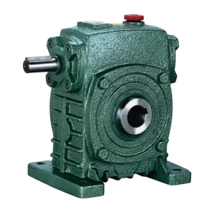
EP-WPKS — 4~365kg 단일 속도 감속기
The WPKS series spans 4 kg to 365 kg, covering a wide output torque range for shock-load applications. The hollow-bore shaft-mounted configuration eliminates the coupling assembly, reducing mechanical interfaces through which shock loads can be amplified. For agricultural and mining drives in Australia, Canada, and Brazil where the service factor calculation drives required rated torque 1.75–2.5× above steady-state, the larger WPKS frames provide the structural rigidity and vibration damping of heavy cast-iron housing mass. The 10:1 to 60:1 ratio range covers most agricultural and processing drive requirements at the 단일 속도 감속기 level.
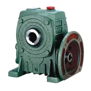
EP-WPDKA — 5 to 350 kg Single Speed Reducer
The WPDKA series covers 5 kg to 350 kg with a dual shaft input configuration allowing power from either side of the housing — used in agricultural machinery where the 단일 속도 감속기 must accept PTO engagement from either direction. For crusher and auger drives in UK and South Korean agricultural facilities where frequent reversals and impact loads are normal, the WPDKA’s larger frame mass and extended shaft length options provide the bearing span and housing rigidity needed to handle repeated shock events without progressive gear mesh deterioration over the service interval.
Common Service Factor Calculation Mistakes to Avoid
The following four mistakes account for the majority of premature 웜 기어 감속기 failures in heavy-duty applications reported in North American and European maintenance records. Each represents a specific calculation or classification error that causes a 단일 속도 감속기 to be specified with insufficient torque margin for its actual operating environment.
Using Motor Nameplate HP Instead of Load Torque
The motor nameplate power does not represent the actual load on the 단일 속도 감속기 — it represents the motor’s capacity. A 2.2 kW motor driving a lightly loaded conveyor imposes far less than 2.2 kW on the gearbox. Always calculate load torque from the actual driven machine resistance, not from the motor rating.
Applying SF to Motor Power Rather Than Output Torque
The service factor applies to the required rated output torque of the 단일 속도 감속기, not to the motor power input. Applying SF to motor power yields a different answer because the efficiency of the worm gear stage — typically 60–85% depending on ratio — is not accounted for correctly when starting from the input side.
Ignoring Thermal Rating After SF Calculation
Stepping up a frame size to meet the SF-adjusted torque requirement sometimes creates a 단일 속도 기어 감속기 whose thermal power rating is now larger than necessary, which is fine. But in some cases the larger frame is still thermally undersized for continuous operation at high input speed. Always verify thermal rating separately from mechanical torque rating after the SF calculation is complete.
Classifying Moderate Shock Applications as Uniform Load
Engineers sometimes classify screw conveyors, agitators, and food mixers as uniform load to allow a smaller gearbox frame size. These are moderate shock applications per AGMA 6034. A SF of 1.0 applied to a screw conveyor — when 1.5 is the correct minimum — reduces gearbox service life to a fraction of its designed value, particularly in US food processing facilities where continuous 16-hour shifts are typical.
호환 가능한 드라이브 시스템 구성 요소
A shock-load 단일 속도 감속기 drives most effectively as part of a correctly matched system. The motor and downstream gear components should be specified alongside the gearbox to ensure the complete drivetrain handles peak transient loads without failure at any interface — not just at the gearbox housing.
전기 모터
For shock-load applications, the 모터 paired with a 단일 속도 감속기 should itself be specified with a service factor applied — motors rated for intermittent or shock-load service carry higher insulation ratings and winding reinforcement that resist thermal and mechanical stress from frequent start-stop or high-inertia load cycles. IEC frame motors with IP55 or IP65 enclosures are standard in most US, Australian, and European shock-load applications where dust or moisture exposure accompanies the mechanical duty.

웜 기어박스
Where a single-stage ratio is insufficient or where thermal management requires splitting the reduction across two stages, a worm gearbox in a double-stage configuration allows each stage to operate at a lower, more thermally efficient ratio. For heavy shock applications in South Korean and Netherlands-based industrial facilities, a two-stage solution also allows a more generous service factor to be applied at each stage rather than demanding the full SF burden from a single-stage 웜 기어 감속기.

제조 시설에 대하여
Our production facility manufactures industrial and agricultural power transmission equipment — worm gear reducers, planetary gear drives, agricultural gearboxes, power take-off shafts, hydraulic cylinders, gears, sprockets, chains, and motors. The 단일 속도 감속기 series covers foot-mounted and shaft-mounted configurations across the WP family of frame sizes, with housing materials spanning ductile iron, grey cast iron, cast steel, precision cast steel, and cast aluminum. Gears, sprockets, worm gears, pulleys, worms, and shafts — both standard catalog and non-standard parts to customer drawings — are produced in-house under ISO 9001:2015 quality management certification. As a 단일 속도 감속기 제조업체 with export programs serving customers in the USA, UK, Australia, Canada, the Netherlands, Brazil, South Korea, Colombia, and other international markets, we offer OEM customization, private-label supply, and application sizing support for shock-load drive specifications.
작업장




자주 묻는 질문
These questions address the practical concerns that engineers in the USA, UK, Australia, Canada, and other markets raise when specifying a 단일 속도 감속기 for shock-load service factor calculations.
How do I calculate the correct service factor for a single speed reducer driving a grain crusher in a Canadian agricultural facility that operates 16 hours per day?
A grain crusher falls in the heavy shock category per AGMA 6034-B92, so the service factor at 16 hours per day is 2.25. Calculate actual output torque from the crusher’s drive shaft resistance load — not from the motor nameplate — then multiply by 2.25 to find the minimum rated output torque the 단일 속도 감속기 must carry. Also verify the thermal power rating at your input RPM after the frame is selected; the SF-driven frame step-up usually resolves thermal concerns as well, but always confirm both ratings separately before finalizing the selection.
What service factor should be applied to a single stage speed reducer on a conveyor system in an Australian mining facility that experiences frequent jam-clearance impacts?
Jam-clearance impacts elevate a conveyor from moderate shock to heavy shock, because the peak torque during a jam event — where the conveyor is stopped by an obstruction and restarted under load — can be three to four times the steady-state torque. For an Australian mining conveyor with documented jam events, a service factor of 2.0 at 8 hours/day or 2.25 at 16 hours/day is appropriate. If jam events occur more than once per shift, some engineers add 0.25 to account for cumulative fatigue effects on the 단일 속도 감속기 worm wheel material. Document the reasoning for the selected SF value so the selection can be reviewed if a failure event occurs.
Which frame size of single speed worm gear reducer should be selected when the service factor calculation doubles the required rated torque beyond the standard motor-matched size?
Step up to the next frame in the WP series until the published rated output torque at the required ratio meets or exceeds your T_rated_required. WP series frame sizes scale in discrete steps (40, 50, 60, 70, 80, 100, 120, 135, 155, 175, 200, 250), with each step increasing rated torque by roughly 30–60%. For a 단일 속도 감속기 application where the SF doubles the torque requirement, ending up two frame sizes above the motor-matched selection is the correct engineering outcome. Confirm that the larger frame’s input bore dimensions remain compatible with your motor shaft before finalizing the order.
How does a hollow-bore shaft-mounted single speed reducer affect the service factor calculation when overhung load is also present in a UK packaging line application?
Overhung load adds a radial stress component to the driven shaft’s bearings that exists independently of the shock-load torque. The standard AGMA service factor calculation addresses shock torque magnitude but does not automatically account for overhung load-induced bending stress. For a UK packaging line shaft-mounted unit where both moderate shock and significant overhung load are present, it is common practice to add 0.25 to the SF obtained from the standard table. A more precise approach involves separately calculating the overhung load-induced bearing stress and verifying the bearing L10 life under combined radial and torque load — but the +0.25 empirical adjustment is widely accepted for 단일 속도 감속기 specifications where full bearing life analysis is not performed.
Where can OEM machine builders in the Netherlands or South Korea source a customized single speed reducer with a confirmed rated torque for a specified service factor?
OEM builders in the Netherlands, South Korea, and other international markets can submit the service factor calculation output — required rated torque, ratio, daily operating hours, and shock class — directly to our export engineering team for frame selection and technical confirmation. We can confirm that the selected 단일 속도 감속기 meets both the SF-adjusted mechanical requirement and the thermal power rating at your input conditions, and supply dimensional documentation for machine integration. For OEM programs requiring volume supply, we can also provide application-specific rating documentation that supports design review and CE or similar regulatory requirements in European and Asian markets.