
Water & Wastewater Treatment · Dewatering Drive Engineering · Worm Gear Reducer Technology
Dewatering is one of the most mechanically demanding stages in any sludge management process. Centrifuges spin at high differential speeds to separate bound water from solids, while belt filter presses squeeze sludge cake between tensioned polymer belts driven by a carefully controlled roller system. Both machine types impose sustained, cyclic, and occasionally shock loads on their drive trains. The pengurang kelajuan tunggal — specifically the worm gear configuration — occupies the critical position between motor and driven shaft, converting motor rpm into the torque-dense, steady output these machines require. Selecting the right unit for dewatering duty demands attention to torque capacity, thermal performance, sealing integrity, and the mechanical geometry of the machine frame.
The Drive Challenge in Sludge Dewatering Equipment
A decanter centrifuge used in municipal biosolids processing runs two concentric shafts at different speeds — the bowl and the scroll conveyor — each driven independently. The scroll drive, which moves dewatered cake toward the discharge end against the centrifugal force of incoming sludge, operates at a differential speed of just 1–20 rpm relative to the bowl. Achieving that differential through a fixed mechanical ratio is exactly where a single stage speed reducer earns its place: the reduction ratio locks the scroll output to a specific fraction of the bowl speed with no electronics and no feedback loops required for standard throughput applications.
Belt filter presses present a different but equally demanding scenario. The belt drive rollers must turn at consistent, low circumferential speed — typically 1–5 m/min belt travel — under variable normal force as sludge moisture content fluctuates during a shift. A worm speed reducer paired with a constant-speed motor delivers this steady output without the speed variation that a lightly loaded variable frequency drive can introduce at low frequency setpoints. The inherent self-locking property of high-ratio worm mesh also prevents belt reverse-travel when the drive de-energizes, protecting the belt tensioning system from sudden slack-load events.

Struktur Pembuatan
The structural core of a WP-series single speed reducer is an integrally cast housing that encloses a right-angle worm-and-wheel gear mesh. Integral casting — where the housing is produced as a single piece rather than bolted subframes — is not incidental; it determines bearing seat concentricity, shaft parallelism, and gear mesh backlash across the full service life of the unit. In dewatering applications where the reducer is running 16–24 hours per day, often six or seven days per week, dimensional stability under sustained thermal cycling matters far more than it would in an intermittent-duty installation.
The input shaft runs in the horizontal axis and drives the worm, which meshes with a bronze wheel mounted on the perpendicular output shaft. This 90-degree shaft arrangement accommodates the typical layout of belt press and centrifuge drives, where motor and gearbox mount on a horizontal frame rail and the driven shaft connects vertically or laterally to the process machine. The WP series offers both foot-mounted and flange-mounted input options, allowing direct IEC motor coupling without external bell housings. The breather-vent-drain plug system manages thermal pressure cycling, and the seals are housed in machined bores — not clamped in covers — to maintain concentricity under axial and radial shaft loads.
Sistem Bahan
Material selection defines how a single speed gear reducer performs under the specific combination of corrosive humidity, sustained torque, and thermal cycling found in wastewater dewatering halls. The housing is cast from grey iron (HT200 or equivalent) in the standard WP line, with nodular cast iron available in the heavier WPKA and WPDKA frame variants. Grey iron provides good vibration damping and adequate compressive strength for the housing-bearing seat interface. Nodular iron is preferred where impact loads from slug flow or centrifuge bowl imbalance events are expected to transmit back through the gear train.
The worm is produced from 20CrMnTi or 40Cr alloy steel, carburized and case-hardened to a surface hardness of 56–62 HRC, then ground to a finish that controls tooth form and lead error within the gear quality grade. The opposing worm wheel uses phosphor bronze — typically ZCuSn10Pb1 — whose low sliding friction against the hardened worm flank and capacity to embed abrasive particles without scoring the mating surface make it the standard for continuous-duty worm drives. Output shafts are medium-carbon alloy steel, finish-machined and supported by deep-groove ball bearings or tapered roller bearings depending on the expected axial thrust component from the driven machine. Bearings are sourced from recognized manufacturers including C&U, NSK, and SKF-equivalent grade.
Drive Parameters for Dewatering Machine Types
WP-series single stage speed reducers span an input power range of 0.12 kW to 33 kW, with input speeds from 750 to 1,500 rpm and single-stage reduction ratios from 1:10 to 1:60. Output torque reaches approximately 9,000 N·m at the largest frame sizes. For belt filter press roll drives — where typical roll diameters of 400–900 mm running at 1–5 m/min belt speed require output shaft speeds in the 0.4–4 rpm range after accounting for circumference — a double-stage WP configuration or a 1:40–1:60 single stage unit paired with a secondary chain drive achieves the target speed economically.
For scroll conveyor drives in decanter centrifuges, output speed relative to the bowl is the governing parameter. In many municipal installations, the scroll differential falls in the 10–30 rpm range, which maps cleanly to single-stage WP unit ratios of 1:40–1:60 off a 4-pole motor. High torque worm gearbox configurations are selected when the centrifuge processes high-solids sludge — digested primary biosolids, industrial food-processing effluent, or pulp-and-paper white-water sludge — where dewatered cake compaction resistance at the discharge cone creates sustained back-torque on the scroll shaft.
Recommended Model: EP-WPKA for Heavy Dewatering Duty
For belt filter press and high-solids centrifuge applications where the drive must sustain high output torque around the clock, the EP-WPKA (5–260 kg Single Speed Reducer) covers the mid-to-heavy duty bracket. The WPKA designation indicates a vertical input with keyed hollow output, which suits roll shaft coupling in belt press drive trains without requiring an external adapter coupling or bell housing. Its weight range of 5–260 kg places it across a span of frame sizes appropriate for small pilot-scale presses through full-scale municipal installations.
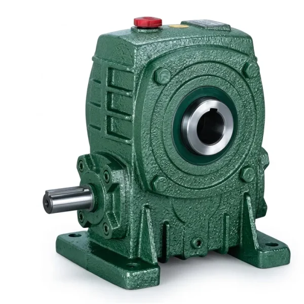
- Weight range: 5–260 kg (scales with frame size)
- Reduction ratio: 1:10 to 1:60 (single stage)
- Vertical input with hollow keyed output shaft
- Suitable for belt press roll and centrifuge scroll drives
- Oil-bath lubrication; cast iron housing
- Operating temperature: −40°C to +40°C ambient

Thermal Performance and Continuous-Duty Rating
Worm gear reducers generate more heat per unit of transmitted power than parallel-axis helical units, because the sliding contact between worm and wheel produces friction losses that manifest as heat in the housing. In belt filter press duty — which typically runs 8–16 hours per shift with brief idle periods — this heat accumulates in the oil and housing until a thermal equilibrium is reached. The gear oil viscosity at equilibrium temperature determines the lubrication film thickness at the mesh contact, which in turn governs wear rate. Running a reducer above its thermal limit — where housing surface temperature exceeds roughly 70–80°C — breaks down oil film thickness and accelerates bronze wheel wear.
For this reason, continuous-duty thermal rating is as important as static torque rating when specifying a single stage speed reducer for a dewatering application. The thermal rating is published in the manufacturer’s catalog as the maximum transmissible power at thermal equilibrium for a given reduction ratio and ambient temperature. In practice, if the calculated running power demand approaches or exceeds the thermal rating, a unit one frame size larger is selected — not because the smaller unit lacks static torque capacity, but because the additional housing surface area of the larger frame dissipates heat faster and maintains oil temperature within the correct viscosity band. For 24/7 continuous operation in enclosed warm pump rooms above 25°C, a forced cooling fan or external oil cooler may be specified alongside the reducer.
Sealing Integrity in Chemically Aggressive Dewatering Environments
Dewatering halls in municipal treatment plants and industrial effluent facilities are not benign environments for mechanical drive components. Belt presses spray polymer-conditioned sludge across a wide zone around the press frame, and centrifuge discharge areas carry aerosol from the spinning bowl. The shaft seals on a single speed reducer must prevent gear oil from migrating outward along the shaft and must prevent process moisture, polymer residue, and hydrogen sulfide from entering the housing.
WP-series reducers use lip-type oil seals pressed into machined bores, selected from CFW, CTY, or SKF-equivalent grades rated for oil-contact service. The output shaft journal at the seal contact band is finish-ground and, in corrosive applications, chrome-plated or induction-hardened to extend seal life by preserving the smooth running surface the lip depends on. The breather plug prevents pressure build-up that would otherwise force oil past the seal lip during warm-up; in corrosive headworks or digester areas, a desiccant breather can be substituted for the standard open vent to exclude humid air during the pressure equalization cycle. Housing exterior finishing — standard epoxy primer — provides the first corrosion barrier; polyurethane topcoat is available for installations near chlorination points or areas with elevated hydrogen sulfide levels.
Service Factor Application for Dewatering Drive Selection
Service factor is the multiplier applied to calculated running torque before matching to a reducer catalog rating. For belt filter press and centrifuge scroll drives, the service factor is not a conservative formality — it captures a real mechanical reality. A belt press starting under wet sludge load pulls two to three times its running current for the first few seconds of each start; a centrifuge scroll engaging against compacted cake can spike to five times running torque momentarily. The reducer output shaft, worm wheel teeth, and key-shaft interface all experience these peaks.
Standard practice for sludge dewatering equipment specifies a service factor between 1.5 and 2.5, with the higher end applied when the process fluid is industrial wastewater with variable solids loading, when the drive starts more than six times per hour, or when process upset conditions can stall the driven machine. A service factor of 2.0 applied to a calculated 300 N·m running torque requires selection of a unit rated at 600 N·m output — which in WP-series terms moves the selection to a larger center-distance frame. This is the most common sizing error in dewatering drive specification: selecting on running torque alone and discovering the unit overloads on every cold start.

Maintenance Practices for Dewatering Drive Reducers
A worm gear speed reducer in continuous belt press or centrifuge service requires a structured maintenance routine that is proportional to the severity of the duty. The oil change interval — 2,000–3,000 hours under standard conditions — shortens to 1,500 hours when operating ambient temperatures routinely exceed 35°C, which is common in enclosed centrifuge rooms with poor ventilation. Synthetic ISO VG 220 gear oil is preferred over mineral grade in these conditions: it maintains viscosity index across a wider temperature range and resists oxidation longer in high-temperature continuous operation.
Lip seal inspection is the second critical maintenance action in wastewater environments. A seal that is weeping gear oil creates a slip hazard on a belt press walk platform and attracts polymer and sludge residue that accelerates external corrosion of the housing. Seal replacement at 8,000–10,000 hours is standard under normal conditions; in H₂S-rich environments, earlier inspection at 5,000 hours is warranted. Vibration monitoring at the bearing housings — a quarterly 10-second envelope measurement — provides the earliest warning of worm wheel deterioration, typically appearing as a sideband at wheel tooth meshing frequency before any audible or thermal change is noticeable.
Komponen Sistem Pemacu yang Serasi
A complete dewatering drive system extends beyond the single speed reducer. Two product families pair directly with the WP-series units and are available from the same supply source, simplifying procurement and ensuring dimensional compatibility at every interface.


Tentang Kami
The manufacturing portfolio spans agricultural gearboxes, worm gear reducers, planetary gear drives, power take-off shafts, hydraulic cylinders, gears, chains, and motors — produced under an ISO 9001:2015 certified quality management system. Design and production capacity covers a broad range of industrial and agricultural gearboxes and assemblies manufactured from ductile iron, cast iron, cast steel, precision cast steel, and cast aluminum. Standard and non-standard mechanical parts — gears, sprockets, worm gears, pulleys, worms, and shafts — are produced in-house, supporting a genuine one-stop supply model for complex drivetrain requirements across treatment plant and process industry projects worldwide.
Kedai Kerja




Soalan Lazim
Editor: PXY