
AUTOMOTIVE & HEAVY EQUIPMENT — APPLICATION INSIGHT
Parts washing conveyors in automotive manufacturing plants operate in some of the most chemically aggressive and moisture-laden environments found in industrial production. This guide examines how a single speed reducer must be specified and constructed to survive continuous immersion-spray exposure, alkaline cleaning chemistry, and high-pressure rinse cycles — while delivering the steady, low-speed torque that washing conveyor chains require around the clock.
Wet Environment Drive
Parts Washing Conveyor
Worm Gear Reducer
Automotive Cleaning Lines
The Parts Washing Environment and What It Demands from Drive Equipment
Automotive parts washing conveyors serve a critical function in engine, transmission, and body-component manufacturing lines. Before assembly, machined castings, stampings, forged brackets, and precision-turned shafts must be cleaned of cutting fluid residue, metal fines, rust-preventive oils, and surface oxide — all of which would compromise adhesive bonding, gasket sealing, or coating adhesion if allowed to carry over into the assembly station. The cleaning is performed by conveyor systems that carry parts through spray chambers where hot alkaline aqueous detergents, high-pressure rinse water, and sometimes phosphate conversion chemistry are applied in sequence.
The drive system for these conveyors — typically a chain and sprocket arrangement running a mesh belt, a slat conveyor, or a monorail carrier system — must function in direct proximity to this chemical environment. Cleaning solution mist, steam, and occasionally direct water spray reach the conveyor drive station, even when enclosures are fitted. A single speed reducer positioned at the drive end of such a conveyor will be exposed to alkaline pH solutions (pH 9–13 for most industrial parts washers), elevated ambient temperature from wash chamber steam (often 50–70°C sustained), and periodic pressure washdown of the entire conveyor structure as part of preventive cleaning schedules.
Drive component failures in parts washing conveyors in German, US, Japanese, and Korean automotive plants are disproportionately caused by seal degradation from chemical exposure rather than mechanical fatigue from normal load. This means the selection of a single speed reducer for washing conveyor service is fundamentally different from selecting for a dry production line: sealing architecture, housing surface treatment, and lubricant compatibility with chemical exposure each carry equal weight alongside the mechanical torque and ratio calculation.

Why a Worm Gear Single Speed Reducer Is Suited to Washing Conveyor Duty
The right-angle worm gear single speed reducer offers several characteristics that align directly with the requirements of parts washing conveyor drives. The compact housing footprint allows the drive unit to be mounted close to the conveyor frame without projecting into the washing chamber or into the operator access aisle alongside it. The enclosed, sealed housing design contains the lubricant internally while keeping the washing chemistry outside — as long as the seal specification is correctly matched to the chemical environment, a point addressed in detail in the material section below.
The worm gear reduction ratio range of 1/5 through 1/60 in a single stage covers the output speed range needed for washing conveyor applications — most mesh belt and slat conveyors in automotive parts washing lines run the drive shaft at 8–30 RPM, which maps directly to standard worm gear reduction ratios from a 4-pole motor at 50 or 60 Hz. The single speed reducer transmission delivers this slow, constant-speed output without the speed ripple that would cause uneven chain tension and basket tipping on lightweight conveyor carriers.
Self-locking at ratios of 1/30 and above is a safety benefit in inclined washing conveyor sections — common in tunnel washers where the conveyor rises from a wash sump through a drain-off zone before entering the rinse chamber. At these elevated ratios, the loaded conveyor chain stays stationary when the motor de-energizes, preventing uncontrolled downhill chain movement that would dump wet, chemically coated parts onto the washer floor. This inherent self-locking behavior eliminates the need for a separate holding brake in inclined washing conveyor sections in facilities across the USA, Italy, and South Korea.
Структура виробництва
The monolithic grey cast iron housing used in the WP series provides the continuous, seam-free external surface that is essential in chemical washing environments. Split housings with parting-line joints are specifically avoided in washing conveyor drive selections because parting-line gaps allow alkaline solution to wick into the joint by capillary action, accelerating corrosion of the joint face and eventually producing internal leakage paths for gear oil outward and washing chemistry inward. The continuous-cast housing also provides a larger external surface for protective coating adhesion — critical when the coating must resist both alkaline detergent splash and the mechanical abrasion of conveyor chain spray deflectors.
In a standard dry-environment single speed reducer, a single-lip NBR oil seal at each shaft exit provides adequate containment. For washing conveyor applications, the seal specification must be upgraded to account for the combination of external chemical pressure and internal oil pressure. Double-lip seals with a grease-filled inter-lip cavity are the standard specification: the outer lip faces the washing chemistry and acts as a first barrier against ingress, while the inner lip retains the gear oil under the slight positive pressure created by thermal expansion of the oil volume during operation. The grease cavity between the lips prevents chemical migration along the shaft surface between the two seal lips — a failure mode specific to aqueous chemical environments that does not occur in dry operating conditions.
The worm shaft and worm wheel material specifications in washing conveyor reducers are identical to standard industrial service: 20CrMnTi alloy steel worm, carburized and ground to 58–62 HRC, paired with ZCuSn10Pb1 phosphor bronze worm wheel. These materials are unaffected by the occasional chemistry contamination that reaches the gear mesh if seal condition degrades during extended operation without maintenance — the bronze wheel does not corrode in the pH range of automotive parts washer chemistry, and the hardened steel worm thread is resistant to pitting from the slightly acidic condensate that forms on cool surfaces in steam-laden washing chambers.
Standard breather vents — which allow internal pressure equalization during thermal cycling — must be replaced with sintered stainless steel filter breathers in washing conveyor applications. An open breather in a parts washer environment draws alkaline mist into the housing during cool-down, contaminating the gear oil with water and detergent chemistry that degrades the oil’s viscosity and anti-wear properties. The sintered stainless filter allows air exchange for pressure equalization while blocking both liquid droplets and the fine mist from spray chambers. For reducers positioned directly above the wash chamber opening, a gooseneck breather tube with the inlet positioned above the spray envelope provides additional protection against direct mist ingestion.
Material System for Wet Chemical Service
Material selection for a single speed reducer in automotive parts washing service requires consideration of three distinct chemical interfaces: the external housing surface exposed to cleaning chemistry, the shaft seal lip exposed to both chemistry and gear oil, and the gear oil itself which may be contaminated by water intrusion over time. Each of these interfaces has a different material vulnerability, and failure at any one of them ultimately compromises the mechanical performance of the worm gear speed reducer regardless of how well the other two are specified.
The following table summarises the material and treatment specification for each component, with the notes column identifying the specific wet-environment vulnerability each choice addresses — a level of detail that is absent from standard catalogue descriptions but matters critically when specifying a single speed reducer for parts washing conveyor service in automotive facilities across Germany, the USA, Japan, South Korea, and Australia.
| Компонент | Material / Grade | Treatment / Specification | Wet-Environment Relevance |
|---|---|---|---|
| Housing (external) | HT200 Grey Cast Iron | Zinc-phosphate pretreat + epoxy primer + alkyd topcoat | Epoxy primer provides chemical barrier against alkaline pH 9–13 detergent splash that degrades standard alkyd-only coatings |
| Ущільнення валу | NBR Double-Lip, Spring-Loaded | Grease-filled inter-lip cavity; garter spring holds lip contact under low-speed conditions | Outer lip blocks aqueous chemistry ingress; inner lip retains gear oil; grease cavity stops capillary migration along shaft |
| Черв'ячний вал | Легована сталь 20CrMnTi | Carburized, 58–62 HRC surface, thread-ground post heat treatment | Hardened surface resists corrosion from acidic condensate; accurate thread geometry supports stable output speed |
| Черв'ячне колесо | ZCuSn10Pb1 Phosphor Bronze | Centrifugally cast bronze ring, finish-hobbed | Bronze does not corrode in alkaline washing chemistry pH range; tin content provides boundary lubrication if oil is briefly water-contaminated |
| Підшипники | Deep-groove ball (input), Tapered roller (output) | C3 internal clearance; ZZ shield option for input bearing | ZZ-shielded input bearing provides secondary protection if inner shaft seal degrades; C3 clearance accommodates thermal expansion from wash chamber steam |
| Gear Oil | ISO VG 220 with emulsification-resistant additive package | Water-resistant demulsifying EP gear oil; change at 200 hours (initial) and annually thereafter | Demulsifying formulation releases any water contamination to the drain plug rather than forming a stable water-in-oil emulsion that accelerates worm wheel corrosion |
| Breather | Sintered Stainless Steel Filter Element | 5-micron filter rating; gooseneck orientation above spray envelope | Blocks detergent mist ingestion during thermal cool-down cycles; maintains dry air exchange for pressure equalization |
| Mounting Hardware | Class 10.9 bolts, zinc-dichromate plated | Thread-locking compound on all external fasteners | Zinc-dichromate coating resists alkaline pH; thread-locking prevents vibration loosening in high-flow wash zones where conveyor vibration is sustained |

Selection Parameters Specific to Parts Washing Conveyor Service
Parts washing conveyor drives share the same fundamental single speed reducer selection sequence — output speed from reduction ratio and motor speed, output torque from chain pull and service factor, frame size from torque and thermal rating — but two parameters are specifically modified for wet service. The thermal rating check must use the elevated ambient temperature inside the washing machine enclosure rather than the nominal 25°C reference temperature typically used in dry-environment selection. At 60°C sustained ambient (common inside tunnel washer enclosures in German and Korean automotive plants), the single speed reducer’s thermal power rating is derated by approximately 15–25% from its 25°C catalogue value — meaning a reducer that appears adequately rated for the motor size at standard conditions may run thermally overloaded when installed inside or immediately adjacent to a wash chamber.
The service factor for wet conveyor duty is also modified upward from the standard continuous-duty value of 1.25–1.5 used for dry conveyors. Parts washing conveyors experience load variation when baskets are loaded unevenly, when drainage from wet parts creates temporary adhesion between parts and mesh belt, and when the conveyor restarts after a cleaning cycle stop with the belt loaded with wet, chemically coated parts. A service factor of 1.5–1.75 is the standard range for roller-chain-driven washing conveyors in Japanese and US automotive parts cleaning lines; 1.75–2.0 is applied for mesh belt conveyors where startup adhesion from wet parts is more pronounced.
| Selection Parameter | Standard Dry Conveyor | Parts Washing Conveyor |
|---|---|---|
| Thermal ambient reference | 25°C (standard) | 50–70°C (inside/adjacent to wash chamber) — derate thermal rating accordingly |
| Service factor | 1.25–1.50 | 1.50–1.75 (roller chain); 1.75–2.00 (mesh belt, wet startup adhesion) |
| Seal specification | Single-lip NBR | Double-lip NBR, grease-filled inter-lip cavity; confirm NBR compatibility with detergent chemistry |
| Покриття корпусу | Standard alkyd topcoat | Zinc-phosphate pretreat + epoxy primer + alkyd topcoat; recoat schedule every 3–5 years |
| Breather specification | Standard cap breather or simple filter | Sintered stainless 5-micron filter breather; gooseneck orientation above spray zone |
| Lubricant specification | ISO VG 220 standard mineral | ISO VG 220 demulsifying EP formulation; water-content oil test at every change |
| First oil change interval | 200–300 hours | 200 hours or earlier — inspect for water contamination at first change; shorten if water content exceeds 0.1% |
Recommended Products for Parts Washing Conveyor Drive Applications
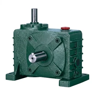
The EP-WPZ is a solid-output-shaft single speed reducer with oil capacity ranging from 0.4 litres at the smallest frame to 5.2 litres at the largest. The oil capacity specification is directly relevant in parts washing service: a larger oil reservoir dilutes any water contamination that penetrates the seal system more effectively, reducing the concentration of water-in-oil that would otherwise reach damaging levels before the scheduled oil change interval. The EP-WPZ’s monolithic housing and standard WP-series shaft sealing arrangement make it a practical base unit for upgrading to double-lip wet-service seals — the seal housings at input and output shafts accept double-lip cartridge replacement seals without requiring additional machining on the housing bore.
For parts washing conveyor applications in automotive facilities in the USA, Japan, and Italy where the conveyor chain pull is modest — light parts baskets, mesh belts running at low speed — the EP-WPZ in frame sizes 60 through 135 covers the motor input range from 0.37 kW to 4.0 kW with standard single-stage worm gear reduction ratios.
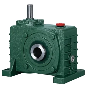
The EP-WPKZ is the hollow-bore output variant of the WPZ series, sharing the same oil capacity range of 0.4 to 5.2 litres and the same frame dimensions. The hollow output bore accepts the conveyor drive sprocket shaft directly through the reducer output hub, eliminating the projecting solid output shaft that would otherwise require a separate flexible coupling and additional exposed hardware in the washing zone. Fewer exposed shaft-seal interfaces means fewer paths for chemistry ingress — in wet environment service, the WPKZ hollow-bore arrangement reduces the total number of shaft seals in the drive assembly by one, compared to a solid-shaft reducer coupled to the sprocket shaft through a standard jaw coupling.
For parts washing conveyors in South Korean and German automotive plants where the conveyor design places the drive sprocket shaft at the same height as the wash chamber floor level — and where a projecting solid output shaft would dip into the cleaning solution splash zone — the hollow-bore WPKZ configuration keeps the reducer entirely above the spray line, with the sprocket shaft extending downward through the output bore rather than projecting outward from it.
Installation Guidance and Maintenance Schedule for Wet Environment Drives
Installing a single speed reducer for parts washing conveyor service requires several precautions beyond the standard installation checklist that applies to dry-environment drives. The mounting bracket must position the reducer above the maximum spray envelope of the wash chamber rather than adjacent to or below it — a point that is straightforward to verify during installation with the washer running at full flow, but is often overlooked in the drive design phase when the spray pattern is not yet characterised. Reducers mounted below the spray envelope accumulate washing chemistry on the housing at a rate that overwhelms even well-specified coating systems within one to two years, regardless of how well the seals are specified.
All cable and conduit entries to the motor mounted on or adjacent to the reducer must be sealed against moisture ingress using gland fittings rated IP65 or higher. The motor connection terminal box must face downward or to the side rather than upward in the washing area, so that condensate runs away from rather than into the terminal box. For motor-flange single speed reducers, verify that the motor’s IP rating matches the washing environment — IP55 minimum for splash zones, IP65 for high-pressure rinse sections.
The maintenance schedule for a single speed worm reducer in parts washing service should include an oil condition check every 500 operating hours in addition to the standard change intervals. At each check, a sample drawn from the drain plug is visually inspected for milky discolouration — the sign of stable water-in-oil emulsification — and checked with a moisture indicator strip. If water content exceeds 0.1% by volume, the oil is changed immediately regardless of the scheduled interval. Seal condition inspection during each oil change is routine: the shaft surface under the seal lip is checked for scoring, and any sign of alkaline residue on the shaft between the seal lip and the housing face indicates outer-lip deterioration requiring immediate seal replacement.
200 operating hours. Drain, inspect sample for water content and metal particles. Refill with fresh ISO VG 220 demulsifying EP gear oil. Record water content baseline for trend monitoring.
Annual or 2,500 hours, whichever comes first, for mineral gear oil. If PAO synthetic is specified, interval extends to 4,000 hours. Condition check at 500-hour intervals between changes regardless of scheduled date.
At every oil change. Inspect shaft surface for scoring or alkaline residue deposits between seal lip and housing face. Replace seals showing outer-lip wear or stiffening from prolonged chemistry exposure before oil ingestion symptoms appear.
Every 12 months. Inspect for coating blistering, flaking, or edge recession at seal housing bores. Spot-recoat with epoxy paint before bare metal areas appear — bare cast iron surfaces corrode rapidly in alkaline chemistry splash zones and produce corrosion product that contaminates parts during cleaning.

Compatible Products for Complete Washing Conveyor Drive Systems
A complete washing conveyor drive system requires the single speed reducer to be paired with compatible motor and gearbox components that share the same environmental resistance standards. Sourcing motor and reducer from the same supplier ensures dimensional compatibility at the motor-to-reducer interface and simplifies the documentation trail required by quality management systems in automotive OEM plants.
Electric motors paired with single speed reducers in washing conveyor applications must carry IP55 or IP65 ratings as a minimum — IP55 for indirect splash zones, IP65 for positions adjacent to high-pressure rinse sections. IEC B5 and B14 flange motors in the 0.12 kW to 15 kW range pair directly with WPZ and WPKZ series reducers via standard IEC pilot circle dimensions. Confirm that the motor terminal box IP rating matches the installation zone and that cable entries use IP-rated gland fittings throughout — the most common wet-zone motor failure in German and Japanese automotive washing lines is terminal box water ingress through unsealed cable entries rather than motor winding failure from ambient moisture.

Beyond the main conveyor chain drive, automotive parts washing lines include ancillary drives for tank agitators, spray pump drives, rinse tank circulation pumps, and overhead spray bar rotators — each requiring its own single speed gear reducer or compact worm gearbox. The full WP and NMRV series covers these ancillary applications: NMRV compact aluminium housing reducers in IP55-rated sealed configurations are commonly used for small agitator and circulation pump drives in Italian and Korean washing line designs, while larger WP series foot-mount reducers serve higher-torque functions such as basket transfer conveyors and parts drying conveyor drives adjacent to the washing line.

Про наше виробниче підприємство
Our production facility manufactures a comprehensive range of industrial power transmission components — worm gear reducers, agricultural gearboxes, planetary drives, power take-off shafts, hydraulic cylinders, chains, gears, and electric motors. All products are manufactured under ISO 9001:2015 certification, with more than 20 years of engineering experience across ductile iron, cast iron, cast steel, precision cast steel, and cast aluminium materials. Gearbox housings, internal gears, worm shafts, and worm wheels are all produced in-house, providing complete material traceability from raw casting through gear cutting, heat treatment, precision grinding, assembly, and outgoing inspection.
Our customers include automotive OEM facilities, tier-1 parts manufacturers, industrial machine builders, and aftermarket replacement programs across North America, Europe (Germany, Italy, Poland, Spain), South America (Brazil, Colombia), the Middle East, Southeast Asia, South Korea, Japan, and Australia. Customized single speed reducer specifications — modified sealing arrangements, non-standard ratios, alternative shaft configurations, and OEM private-label programs — are available for volume requirements with engineering support throughout the design and qualification process.
Часті запитання
Q1. What type of single speed reducer seal specification is required for a parts washing conveyor drive in a German automotive manufacturing plant using alkaline detergent at pH 12?
For a parts washing conveyor drive in Germany operating with alkaline detergent at pH 12, the shaft seal specification must be upgraded from the standard single-lip NBR seal used in dry conveyor applications to a double-lip NBR seal with a grease-filled inter-lip cavity. The outer lip acts as the primary barrier against the alkaline chemistry while the inner lip retains the gear oil; the grease cavity prevents capillary migration of the alkaline solution along the shaft surface between the two lips. Nitrile rubber (NBR) is compatible with the temperature range (40–80°C) and pH range (up to pH 13) of most automotive parts washer detergents — fluoroelastomer (FKM) seals are not necessary for this chemistry unless the detergent formulation contains aromatic solvents or petroleum-based degreaser components. The housing external surface should also carry an epoxy primer under the topcoat, since standard alkyd paint systems degrade within 12–18 months at sustained pH 12 splash exposure.
Q2. How do I calculate the correct worm gear reduction ratio for a tunnel parts washer mesh belt conveyor running at 2 metres per minute in a South Korean automotive engine plant?
For a mesh belt tunnel washer running at 2 m/min in South Korea, begin by identifying the drive sprocket pitch circle diameter — a typical 200 mm pitch circle gives an output shaft speed of 2,000 mm/min divided by (pi × 200 mm) = approximately 3.2 RPM. With a standard 4-pole 60 Hz motor at 1750 RPM input, the required single speed reduction ratio is 1750 / 3.2 = approximately 1/547 — well beyond single-stage worm gear range. This means a double-stage worm reducer or a double-stage ratio combination is required. At 50 Hz (1450 RPM motor), the ratio is 1450 / 3.2 = approximately 1/453, still requiring double stage. For a 2 m/min mesh belt with a smaller 100 mm pitch sprocket, the output speed rises to approximately 6.4 RPM, giving a ratio of 1450 / 6.4 = 1/227 at 50 Hz — still double stage. Single-stage worm reducers (up to 1/60) are appropriate when the belt speed exceeds approximately 8–12 m/min with typical sprocket sizes, or when a secondary chain reduction stage is added between the reducer output and the drive sprocket.
Q3. Which single speed reducer oil grade should be used for a parts washing conveyor drive in a Japanese automotive transmission parts plant where steam and water spray regularly reach the gearbox housing?
For a Japanese automotive plant where steam and water spray regularly reach the single speed reducer housing on a transmission parts washing line, the gear oil specification should be ISO VG 220 with a demulsifying additive package — specifically an EP (extreme pressure) formulation with rust inhibitor and water-separating demulsifiers. The demulsifying additive prevents water that penetrates through a degraded seal lip from forming a stable water-in-oil emulsion: instead, the water separates to the bottom of the oil reservoir where it can be drained at the oil check port before causing corrosion of the worm wheel bronze or the worm shaft surface. Oil condition checks should be performed every 500 hours in steam-exposed installations, with immediate change triggered by any milky appearance or water strip reading above 0.1%. For Japanese facilities operating continuous three-shift washing lines where maintenance access is limited, PAO-based ISO VG 220 with the same demulsifying package provides better water separation performance than mineral oil at the elevated temperatures inside the washer enclosure and allows extended change intervals between planned shutdowns.
Q4. Where can automotive plant maintenance engineers in the USA source a customized single speed reducer supplier who offers hollow-bore output worm drives rated for wet industrial conveyor environments?
Automotive plant maintenance engineers in the USA sourcing hollow-bore single speed reducers for wet washing conveyor service should focus on manufacturers who can confirm three specific capabilities: first, double-lip seal availability in the hollow-bore output configuration — not all hollow-bore worm reducers are offered with upgraded wet-service sealing as a standard option; second, ISO 9001:2015 quality documentation for traceability compliance with automotive OEM supplier qualification requirements (IATF 16949-aligned facilities expect documented material certificates and inspection records with each delivered unit); and third, the ability to supply dimensional drawings and STEP files that include the double-lip seal arrangement — this allows plant engineers to verify that the selected reducer’s output hub geometry clears the conveyor sprocket shaft without pressing against the seal lip at the inner bore edge during installation. Direct factory engagement typically provides faster access to wet-service specification options than sourcing through distribution channels, where wet-service seal upgrades are often non-catalogued and require factory-direct confirmation of availability and lead time.
Q5. When is a worm gear single speed reducer a better choice than an inline helical reducer for driving an inclined parts washing conveyor in an Italian automotive component plant?
A worm gear single speed reducer is the better choice over an inline helical reducer for an inclined washing conveyor in an Italian automotive parts plant when two conditions are present. First, the inclined section requires load-holding when the motor is de-energized: at worm gear reduction ratios of 1/30 and above, the self-locking worm geometry holds the loaded conveyor chain stationary on the incline without requiring a separate brake — a safety-critical function that helical reducers cannot provide at any ratio. Second, the right-angle output shaft arrangement of the worm reducer suits the typical geometry of inclined washing conveyor drive stations better than the inline (parallel shaft) arrangement of a helical reducer, which would require a secondary right-angle bevel stage or an angled motor mounting bracket to redirect the drive to the horizontal conveyor frame drive shaft. The additional drive component count in the helical-plus-bevel arrangement also increases the number of sealed interfaces exposed to the washing chemistry — each additional sealed shaft exit is a potential ingress point in a wet environment, making the simpler worm gear architecture preferable on both safety and maintenance grounds for Italian and other European automotive parts washing line installations.
Редактор: PXY