
GENERAL BUYER GUIDES & COMPARISON
Getting the gear ratio wrong is the most common — and most avoidable — single speed reducer specification error. This guide walks through the calculation sequence step by step, explains how worm gear reduction ratios behave across the 1/5 to 1/60 single-stage range, and provides worked examples for the drive applications engineers and procurement teams encounter most often in industrial production worldwide.
Gear Ratio Calculation
Output RPM Guide
Worm Gear Reducer
Drive Selection
What Is a Gear Ratio and What Does It Mean in a Single Speed Reducer?
The gear ratio of a single speed reducer is the relationship between the number of input shaft revolutions and the corresponding number of output shaft revolutions. In a worm gear single speed reducer, this ratio is set by the number of thread starts on the worm shaft relative to the number of teeth on the worm wheel. A single-start worm paired with a 40-tooth wheel produces a 1:40 ratio — one complete worm rotation advances the wheel by exactly one tooth, so the output shaft completes one full revolution after the input shaft has turned 40 times.
The convention for expressing this ratio varies by region and industry. In most industrial catalogues, a worm gear speed reducer ratio is written as 1/40 or 1:40, both meaning the same thing: the output shaft turns once for every 40 input shaft revolutions. Some catalogues write it as 40:1, expressing the input side first — this is mathematically identical and should not cause confusion as long as it is clear which shaft is input and which is output. In this guide, ratios are expressed as 1/N throughout, where N is the number of input revolutions per one output revolution.
Standard single-stage worm gear reduction ratios in the WP series run from 1/5 through 1/60 in defined steps: 1/5, 1/10, 1/15, 1/20, 1/25, 1/30, 1/40, 1/50, and 1/60. Each step roughly doubles the torque multiplication while halving the output speed relative to the previous step. When the application requires a ratio beyond 1/60, a double-stage reducer — using two sequential worm gear meshes — is required, extending the achievable range up to 1/900 or more.
How to Calculate Output RPM from a Single Speed Reducer
The output RPM calculation for a single speed reducer is straightforward once you know the motor speed and the selected gear ratio. The formula is: Output RPM = Input RPM divided by the ratio denominator. For a standard 4-pole induction motor running at 1450 RPM on a 50 Hz supply (the most common motor speed in European and Australian industrial applications) combined with a 1/20 ratio single speed reducer, the output shaft turns at 1450 / 20 = 72.5 RPM. For the same motor on a 60 Hz supply — common in the USA, Canada, Mexico, and Japan — the synchronous speed rises to approximately 1750 RPM, giving an output of 1750 / 20 = 87.5 RPM.
This 50 Hz versus 60 Hz difference is the most common source of output speed errors in international applications. An engineer in Germany selects a 1/20 reducer for 72.5 RPM output based on a 50 Hz motor; the same gearbox installed in a US facility with a 60 Hz motor produces 87.5 RPM — a 20.7% speed increase that can overload a conveyor chain, exceed a rated agitator shaft speed, or place a rotating mechanism outside its designed operating range. Always confirm the supply frequency and the motor’s actual nameplate speed before finalising ratio selection.
Motor slip is the second calculation variable that is frequently omitted. Induction motors run slightly below synchronous speed due to rotor slip — typically 2–5% below the theoretical value. A 4-pole 50 Hz motor has a synchronous speed of 1500 RPM but an actual nameplate speed of 1400–1450 RPM. The correct input value for ratio calculation is the nameplate speed, not the synchronous speed. Using synchronous speed overestimates output RPM by approximately 3–4%, which may be acceptable in some applications but is significant in speed-sensitive processes such as coating lines, dosing conveyors, and precision indexing mechanisms.
CALCULATION FORMULA
Output RPM = Motor Nameplate RPM ÷ Ratio Denominator
Example 1 — 50 Hz supply:
Motor: 1450 RPM | Ratio: 1/25 | Output: 1450 ÷ 25 = 58 RPM
Example 2 — 60 Hz supply:
Motor: 1750 RPM | Ratio: 1/25 | Output: 1750 ÷ 25 = 70 RPM

Standard Single Speed Reducer Ratio Reference Table
The table below shows calculated output speeds for all standard single-stage worm gear reduction ratios at the two most common motor supply frequencies. Use this as a quick reference during the application sizing phase — the actual nameplate speed of the specific motor should always be substituted for the typical values shown here before finalising the ratio selection.
| Коефіцієнт зменшення | Output RPM (50 Hz, 1450 RPM motor) | Output RPM (60 Hz, 1750 RPM motor) | Typical Application Match |
|---|---|---|---|
| 1/5 | 290 RPM | 350 RPM | Cooling fan drives, pump drives, light agitators at moderate speed |
| 1/10 | 145 об/хв | 175 RPM | Screw feeders, small conveyor drives, mixer paddles, material transfer |
| 1/15 | 97 об/хв | 117 RPM | Industrial conveyors, grain auger drives, general-purpose machine drives |
| 1/20 | 72.5 RPM | 87.5 RPM | Packaging conveyors, agricultural equipment, greenhouse curtain drives |
| 1/25 | 58 RPM | 70 RPM | Roller conveyors, batch mixers, dough dividers, rotary index tables |
| 1/30 | 48 об/хв | 58 RPM | Inclined conveyors (self-locking begins), slow agitators, washing conveyor drives |
| 1/40 | 36 об/хв | 44 RPM | Overhead paint shop conveyors, slat conveyors, heavy scraper drives |
| 1/50 | 29 RPM | 35 RPM | Very slow conveyors, tunnel washer belt drives with chain reduction, winding mechanisms |
| 1/60 | 24 об/хв | 29 RPM | Slow solar tracker drives, very heavy-duty lift mechanisms, precision feed screws with strong self-locking requirement |
Calculating Output Torque from the Gear Ratio
Output torque is the other half of the ratio calculation — and the more critical value for confirming that the selected single speed reducer frame size can physically handle the drive application. The theoretical relationship is: output torque equals input torque multiplied by the ratio, multiplied by the worm gear mesh efficiency. For a worm gear single speed reducer at a 1/20 ratio with approximately 80% mesh efficiency at that ratio, a 0.75 kW motor producing approximately 5 N·m of shaft torque at 1450 RPM delivers a theoretical output torque of 5 × 20 × 0.80 = 80 N·m at 72.5 RPM output.
In practice, the efficiency figure is not constant across the ratio range — it varies significantly with worm gear reduction ratio. At low ratios (1/5, 1/10), worm gear efficiency is relatively high, typically 80–92%, because the worm lead angle is steep enough for efficient power transfer. At high ratios (1/40, 1/50, 1/60), efficiency drops to 50–70% as the lead angle flattens and the proportion of sliding friction in the mesh increases. This efficiency variation is why a worm gear single speed reducer at 1/60 requires substantially more input power than the theoretical load torque divided by ratio would suggest — the gearbox itself consumes a meaningful fraction of the input power as heat. Engineers in South Korea and Japan who specify high-ratio worm reducers for very slow conveyor drives should verify both the mechanical output torque rating and the thermal power rating from the catalogue to avoid thermal overload in extended continuous-duty service.
The service factor applied to the calculated output torque accounts for load variation, startup peaks, and shock loads that the drive will experience in practice. For most conveyor applications, a service factor of 1.25 to 1.5 is appropriate. For shock-loaded applications — mixers with dense material, crushers, or conveyors with frequent emergency stops — service factors of 1.5 to 2.0 are standard. The service factor multiplies the calculated steady-state torque requirement; the result must fall below the single speed reducer’s rated output torque for the selected frame size and ratio combination.
TORQUE CALCULATION SEQUENCE
Step 1 — Motor Output Torque (N·m) = (Motor kW × 9550) ÷ Motor RPM
Example: 0.75 kW at 1450 RPM → (0.75 × 9550) ÷ 1450 = 4.94 N·m input torque
Step 2 — Theoretical Output Torque (N·m) = Input Torque × Ratio × Efficiency
Example: 4.94 × 20 × 0.80 = 79 N·m theoretical output
Step 3 — Required Rated Output Torque = Theoretical Output × Service Factor
Example: 79 × 1.5 = 118.5 N·m — confirm this is below the catalogue rated output torque for the selected frame
Worked Calculation Examples for Common Drive Applications
Requirement: Belt speed 30 m/min, drive roller diameter 200 mm. Required output RPM = 30,000 / (pi × 200) = 47.7 RPM.
Motor: 0.55 kW, 1450 RPM (4-pole, 50 Hz).
Required ratio: 1450 / 47.7 = 30.4 → select 1/30 standard ratio.
Actual output RPM at 1/30: 1450 / 30 = 48.3 RPM (1.3% over target — acceptable).
Result: Single speed reducer at 1/30 ratio, confirm output torque vs service factor 1.25 for light packaging conveyor duty.
Requirement: Auger shaft at 50 RPM, 1.5 kW motor, 60 Hz supply at 1750 RPM.
Required ratio: 1750 / 50 = 35 → no exact match; select 1/40 (conservative) giving 1750/40 = 43.75 RPM.
Actual output: 43.75 RPM — 12.5% below target. Acceptable if auger throughput at 43.75 RPM still meets capacity, or fine-tune by adjusting sprocket sizes in secondary drive.
Service factor: 1.5 for agricultural duty with shock loading from grain compaction. Confirm frame size output torque covers 1.5 × calculated value.
Requirement: Chain speed 5 m/min, drive sprocket 300 mm pitch diameter. Output RPM = 5,000 / (pi × 300) = 5.3 RPM.
Motor: 1750 RPM (60 Hz). Required ratio: 1750 / 5.3 = 330 → beyond single stage (max 1/60). Double-stage reducer required, or single stage plus secondary chain reduction.
Practical solution: 1/60 single speed reducer at 1750/60 = 29.2 RPM, then 29.2 / 5.3 = 5.5:1 secondary chain reduction. Chain drive from 29-tooth sprocket to 160-tooth sprocket achieves approximately 5.5:1, giving 29.2/5.5 ≈ 5.3 RPM at the conveyor shaft.
Key point: The 1/60 worm gear ratio provides inherent self-locking to hold the conveyor chain when the motor is off.
Requirement: Agitator shaft at 20 RPM, continuous duty, 2.2 kW motor at 1450 RPM (50 Hz).
Required ratio: 1450 / 20 = 72.5 → nearest standard is 1/60 giving 1450/60 = 24.2 RPM, or double-stage for 72.5.
Single-stage option: 1/60 at 24.2 RPM — 21% faster than target. Accept if process allows it, or add chain reduction.
Double-stage option: Select WPEDS or similar double-stage unit for exact 1/72 or 1/80 ratio, providing 20.1 or 18.1 RPM. Use double-stage for precision-speed-sensitive mixing processes in Australian chemical and food facilities.

Manufacturing Structure — How Ratio Accuracy Is Built In
The reduction ratio of a worm gear single speed reducer is set by the worm thread pitch and wheel tooth count, but the actual output RPM accuracy depends on the worm thread pitch being held precisely across its full contact length. Thread pitch errors — caused by incorrect grinding wheel dressing, thermal growth during grinding, or distortion from heat treatment — produce a cyclical output velocity variation at the output shaft. For applications where output speed consistency matters (coating lines, dosing mechanisms, precision indexing), worm shafts are ground post-heat-treatment on CNC gear grinding machines to eliminate pitch distortion. This post-grind sequence is the production step that translates a theoretical ratio into an accurate, repeatable output shaft speed in service.
The worm wheel tooth count is the other half of the ratio equation. Worm wheels are finish-hobbed to the exact tooth count for the intended ratio — a 40-tooth wheel for 1/40, a 50-tooth wheel for 1/50, and so forth. The hobbing process uses the same module and pressure angle parameters as the worm thread, ensuring that the mesh geometry is correctly matched. Tooth count errors in worm wheels are rare in production because hobbing is a deterministic counting process, but tooth profile errors from worn or incorrectly dressed hobs produce mesh contact geometry errors that reduce efficiency and increase operating temperature — both of which affect the real-world output torque available at the shaft.
The centre distance between the worm shaft axis and the output shaft axis determines the gear mesh geometry in conjunction with the worm and wheel module. If the bearing bore positions in the housing deviate from the designed centre distance, the worm and wheel mesh either tightly (causing binding and elevated temperature) or loosely (causing backlash and velocity variation). Bearing bores in production WP series housings are finish-bored on CNC machining centres to tolerances that maintain centre distance accuracy across production batches, ensuring consistent ratio behaviour from unit to unit. This is particularly important for multi-machine production lines in German and Japanese automotive facilities where multiple single speed reducers drive parallel conveyor sections at matched speeds.
Material System and Its Effect on Ratio Stability Over Time
The output RPM of a single speed reducer drifts over its service life if the gear mesh materials wear at a rate that changes the effective worm thread and wheel tooth profiles. A worm wheel that loses tooth material through abrasion or fatigue pitting produces an increasingly loose mesh, which increases backlash and introduces velocity variation at the output shaft. The material pairing of hardened alloy steel worm (20CrMnTi, 58–62 HRC) and phosphor bronze wheel (ZCuSn10Pb1) is the industry standard for worm gear speed reducers precisely because it minimises this wear rate: the harder steel worm thread beds in against the softer bronze wheel during the first operating hours, producing a conforming contact area that distributes load over a larger surface — reducing contact stress and slowing subsequent wear to a rate that keeps output RPM stable across thousands of operating hours.
Oil viscosity directly affects the film thickness between the sliding worm and wheel surfaces. Using the wrong viscosity — too thin for the operating temperature, or the wrong additive type for the worm gear sliding contact mode — increases metal-to-metal contact frequency and accelerates surface wear. ISO VG 220 is the standard specification for WP series single speed reducers, selected to provide adequate film thickness at the combination of worm thread sliding speed and operating temperature encountered in most industrial applications. In facilities in Brazil, Australia, or Southeast Asia where ambient temperatures regularly exceed 35°C, monitoring oil temperature and switching to synthetic ISO VG 220 when housing surface temperature consistently exceeds 65°C is the most effective single maintenance action for extending mesh accuracy and output speed consistency.
Product Recommendations by Ratio Range
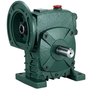
The EP-WPDS covers all nine standard worm gear reduction ratios from 1/5 through 1/60 across frame sizes 40 through 250, with input power ratings from 0.12 kW at the smallest frame to 15 kW at the largest. This breadth makes it the most versatile single-product selection tool for ratio-based application sizing: an engineer can calculate the required ratio, identify the required output torque (with service factor), and find a matching EP-WPDS frame size and ratio combination in a single catalogue consultation. The WPDS designation indicates a foot-mounted, flange-compatible unit with a solid output shaft — the standard configuration for most conveyor, mixer, and agricultural drive applications where ratio accuracy and output torque consistency across a production run are the primary selection criteria.
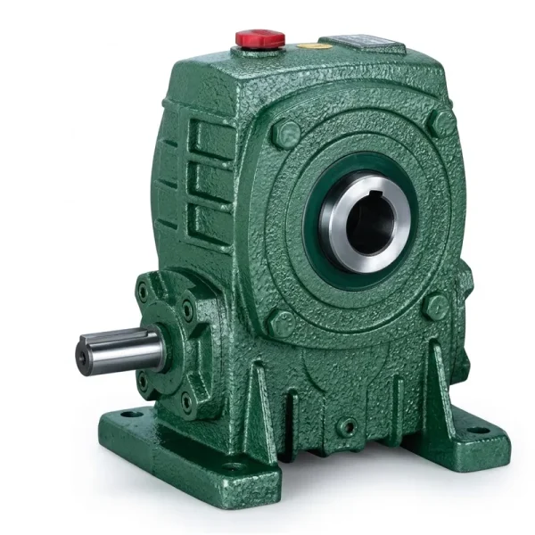
The EP-WPKA is a hollow-bore output single speed reducer covering the 5 to 260 kg unit weight range across frame sizes, with the same standard 1/5 through 1/60 ratio range as the WPDS solid-shaft series. For applications where the exact ratio is calculated and a hollow-bore shaft-mount arrangement is preferred — screw conveyors, shaft-mounted agitators, direct-mount sprocket drives — the WPKA provides ratio selection flexibility equivalent to the solid-shaft series. The hollow-bore output hub accommodates standard shaft keyway dimensions W×Y as specified in the dimensional table, allowing ratio-focused selection to proceed in parallel with the mechanical coupling design without treating the two as sequential steps.
Common Ratio Selection Mistakes and How to Avoid Them
Synchronous speed (1500 RPM at 50 Hz for 4-pole) is always slightly higher than actual nameplate speed (1400–1450 RPM) due to motor slip. Using synchronous speed overestimates output RPM by 3–7%. For most conveyor drives this is acceptable, but for speed-sensitive applications — metering pumps, coating rollers, precision feed mechanisms — always use the actual nameplate speed printed on the motor data plate.
A 1/30 ratio single speed reducer delivers 48 RPM from a 50 Hz motor but 58 RPM from a 60 Hz motor — a 21% speed difference on a shared gearbox design. For multinational OEM programs supplying equipment to both European (50 Hz) and North American or Japanese (60 Hz) markets, this difference must be designed into the conveyor speed specification and compensated by adjusting either the ratio selection or the drive sprocket diameter.
Standard worm gear reduction ratios jump in large steps — from 1/25 to 1/30 is a 20% increase, and from 1/40 to 1/50 is 25%. When the calculated required ratio falls in the middle of a step, selecting the lower ratio produces higher-than-target output RPM; selecting the higher ratio produces lower-than-target RPM. Verify that the actual output RPM from the selected ratio is within the application’s acceptable speed tolerance before finalising the selection.
A worm gear single speed reducer may be mechanically sized correctly for the output torque but thermally overloaded in continuous S1 service. High-ratio units (1/40, 1/50, 1/60) run at lower efficiency, generating more heat per kilowatt of input power. Always verify both the mechanical output torque rating and the thermal power rating from the catalogue when specifying high-ratio worm reducers for continuous-duty applications in warm climates (Southeast Asia, Brazil, Middle East) where ambient temperature further reduces thermal headroom.

Compatible Products for Complete Drive System Selection
Once the gear ratio and frame size are confirmed, the remaining drive system components — motor and any secondary transmission elements — must be selected to match the same interface dimensions and power level. Sourcing from a single supplier simplifies this process and removes the risk of flange-dimension mismatches that add cost and delay to installation.
The motor nameplate speed is the starting point of every single speed reducer ratio calculation. Pairing a motor from the same product family as the reducer ensures that the motor shaft diameter, keyway, and flange pilot circle match the reducer’s input bore specification without requiring a custom coupling or adaptor ring. IEC B5 and B14 flange motors from 0.12 kW to 15 kW pair directly with WP series reducers via standard pilot dimensions — eliminating the alignment step and shortening installation time. For applications using VFD speed control to adjust output RPM without changing the gear ratio, confirm the motor’s inverter-duty winding specification.

When ratio calculations produce a required value beyond 1/60 — as demonstrated in the worked examples for slow conveyors and precision agitators — a double-stage worm gearbox extends the achievable range up to 1/900. The WPEDS and WPEOA double-stage series share the same housing mounting footprint as the WP single-stage units, meaning a drive station designed for a single speed reducer can be retrofitted with a double-stage unit if process changes later require a lower output speed — without modifying the base frame or motor mounting.

Про наше виробниче підприємство
Our production facility designs and manufactures a complete range of industrial power transmission components — worm gear reducers, agricultural gearboxes, planetary gear drives, power take-off shafts, hydraulic cylinders, chains, gears, and electric motors — under an ISO 9001:2015 certified quality management system. With over 20 years of engineering and production experience, our team produces gearbox housings, worm shafts, worm wheels, and assembled gearboxes in ductile iron, cast iron, cast steel, precision cast steel, and cast aluminium to DIN, ISO, ANSI, JIS, and AGMA dimensional standards.
All gear cutting, heat treatment, CNC worm thread grinding, assembly, and outgoing inspection are carried out in-house, ensuring complete material traceability from raw casting to finished single speed reducer. Our customers include industrial machine builders, agricultural equipment manufacturers, conveyor system integrators, and aftermarket replacement programs across North America, Europe (Germany, Italy, Poland, Spain), South America (Brazil, Colombia, Argentina), the Middle East, Southeast Asia, Japan, South Korea, and Australia.
Custom ratio configurations, modified shaft dimensions, and OEM private-label programs are available for volume requirements. Engineering support for ratio calculation verification, thermal rating checks, and mounting arrangement review is provided as a standard part of the product supply process.
Майстерня




Часті запитання
Q1. How do I calculate the correct output RPM for a single speed reducer driving a conveyor belt at 15 metres per minute in a German packaging plant using a 50 Hz motor?
Start by determining the required output shaft speed from the conveyor belt speed and drive roller dimensions. If the drive roller has a 150 mm pitch diameter, the circumference is pi × 150 = 471 mm. For 15 m/min belt speed, the shaft must turn at 15,000 / 471 = 31.8 RPM. With a standard German 50 Hz motor at a typical nameplate speed of 1450 RPM, the required worm gear reduction ratio is 1450 / 31.8 = 45.6 — nearest standard ratio is 1/40 (giving 1450/40 = 36.25 RPM, 14% faster than target) or 1/50 (giving 1450/50 = 29 RPM, 8.8% slower). If 36.25 RPM is within the belt speed tolerance, select 1/40; if the process requires closer speed match, adjust the drive roller diameter or add a secondary chain stage to fine-tune. Always use the motor nameplate speed rather than the 1500 RPM synchronous value to avoid a 3–4% output speed overestimate.
Q2. What is the purpose of a single speed reduction gear in a worm gear reducer, and how does it differ from a multi-stage gearbox used in Australian agricultural machinery?
The purpose of the single speed reduction in a worm gear reducer is to achieve the entire speed ratio between motor and driven shaft in one gear mesh stage, using the worm thread advancing the wheel teeth sequentially. This single-stage approach limits the maximum achievable ratio to approximately 1/60 but keeps the gearbox compact, lightweight, and mechanically simple — all attributes that matter in Australian agricultural applications where equipment is field-maintained and spare parts must be carried on remote stations without specialist tools. A multi-stage gearbox — whether double-worm-stage or worm-plus-helical — achieves higher ratios (1/100 to 1/3600 and beyond) but adds shaft count, seal count, bearing count, and oil management complexity. For Australian grain augers, round baler drives, and irrigation pump drives requiring ratios in the 1/20 to 1/60 range, the single speed reducer is the standard selection because it matches the ratio requirement without the added complexity of multi-stage architecture.
Q3. Which worm gear reduction ratio provides the best combination of output torque and efficiency for a 1.5 kW conveyor motor running in a South Korean food processing facility at 60 Hz?
For a 1.5 kW motor in South Korea at 60 Hz (approximately 1750 RPM nameplate), the ratio that provides the best balance of output torque and efficiency depends on the target output speed. At 1/20 ratio (output 87.5 RPM), worm gear efficiency is approximately 82–85% — the 1.5 kW input produces roughly 1.5 × 0.83 × 9550 / 1750 × 20 = approximately 136 N·m output torque available for the conveyor. At 1/40 (output 43.75 RPM), efficiency drops to approximately 65–70%, and the available output torque is approximately 1.5 × 0.67 × 9550 / 1750 × 40 = approximately 220 N·m. So higher ratios deliver more torque at lower speed but consume more input power as heat — in a South Korean food facility running continuous shifts, thermal rating of the reducer at the actual duty cycle must be checked alongside mechanical torque when choosing between 1/30, 1/40, and 1/50 ratios for slow-speed section drives.
Q4. Where can engineering teams in the USA find a customized single speed reducer manufacturer who can supply non-standard worm gear ratios for special-purpose conveyor drives?
Engineering teams in the USA sourcing single speed reducers with non-standard ratios — required when the calculated ratio falls between standard catalogue steps (for example, 1/35 between the 1/30 and 1/40 catalogue values) — should engage directly with manufacturers who perform worm wheel hobbing and worm thread grinding in-house and have the CNC cutting capability to produce custom tooth counts. A standard 1/30 unit uses a 30-tooth worm wheel with a 1-start worm; a custom 1/35 unit requires a 35-tooth wheel, which is achievable by any facility with flexible CNC hobbing equipment. The manufacturer should provide a dimensional drawing confirming that the custom wheel fits within the same housing as the standard ratio unit — custom tooth counts sometimes affect the gear centre distance and may require a modified housing or housing bore if the pitch circle diameter grows beyond the standard clearance envelope. Request 3D STEP file data for verification before placing an order on a custom ratio unit for a new machine design.
Q5. When should I use a VFD to adjust output speed instead of selecting a different single speed reducer gear ratio for a variable-speed industrial drive in a Brazilian manufacturing plant?
Using a VFD (variable frequency drive) to adjust output speed — rather than changing the single speed reducer gear ratio — is appropriate when the application requires continuous, stepless speed adjustment during operation rather than a fixed output speed. Examples in Brazilian manufacturing include conveyor systems that adjust speed to match production rate variations across shifts, mixing drives that change speed between different product batches, and winding line drives that reduce speed as the roll diameter grows to maintain constant surface speed. The practical limit of VFD speed reduction below the motor’s base frequency is approximately 20–30 Hz (67–57% of rated speed at 60 Hz), below which motor torque delivery becomes unreliable and thermal management of the motor requires either a separately powered cooling fan or reduced load. For output speeds that require motor frequency below 20 Hz to achieve the target RPM at a given single speed reducer ratio, selecting a higher ratio reducer and running the motor closer to its base frequency is the preferable engineering approach — particularly in Brazilian facilities where VFD-sourcing and maintenance expertise may be more limited in smaller manufacturing sites outside the major industrial centres.
Редактор: PXY