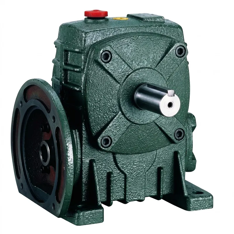
Pengurang Kelajuan Tunggal EP-WPDA 0.12–15 kW
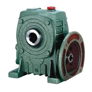
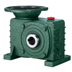
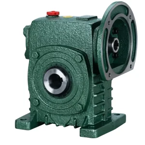
The EP-WPDA is a flange-integrated single speed reducer built around a right-angle worm-and-wheel mesh. Its defining feature relative to the standard WPS series is the machined motor-flange face cast into the input housing, which accepts IEC-standard motor flanges directly — the motor bolts onto the gearbox, the motor shaft slides into a precision-bored hollow input hole, and the assembly is ready to mount.
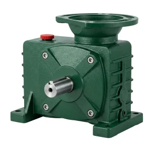
Frame sizes run from 40 through 250, covering input power from 0.12 kW on the smallest unit up to 15 kW on the largest. The motor input hole (Q bore) accepts motor shaft diameters from 11 mm on size-40 up to 42 mm on size-250, with a keyway and set-screw retention system that transmits input torque without fretting even at the duty cycles that worm gear speed reducers encounter in 24-hour processing plants. The output shaft, supported on taper roller bearings, delivers the reduced-speed torque directly to the driven equipment, with shaft dimensions scaling from 28 mm on size-40 to 155 mm on size-250.
The WPDA single speed reducer transmission is offered with five standard gear ratios — 1/5, 1/10, 1/15, 1/20, 1/25, 1/30, 1/40, 1/50, 1/60 — though not every ratio is available on every frame size. Selecting the correct ratio is a matter of dividing rated motor speed (typically 1,400–1,450 rpm for a 4-pole IEC motor) by the required output speed, then choosing the nearest standard worm gear reduction ratio.
Motor-Flange Integrated Worm Drive
EP-WPDA 0.12–15 kW
Pengurang Kelajuan Tunggal
A flange-mount single speed reducer with integrated motor connection, engineered for direct-coupled worm gear transmission across industrial and agricultural applications worldwide.
Spesifikasi Teknikal
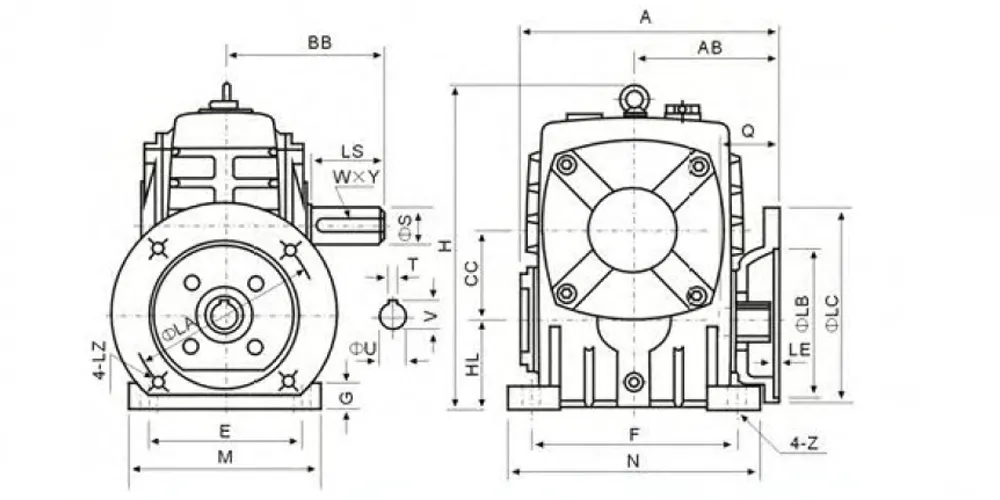
WPDA Series Single Speed Reducer — Full Dimensional & Power Data (dimensions in mm, weight in kg, power in kW)
| Saiz | Kuasa (kW) | Nisbah | A | AB | BB | CC | H | HL | M | N | E | F | G | Z | LA | LB | LC | LE | LZ | Q | U | T×V | LS | S | W×Y | Berat (kg) |
|---|---|---|---|---|---|---|---|---|---|---|---|---|---|---|---|---|---|---|---|---|---|---|---|---|---|---|
| 40 | 0.12 | — | 135 | 75 | 74 | 40 | 138 | 40 | 90 | 100 | 70 | 80 | 13 | 10 | 115 | 95 | 140 | 4 | M8 | 31 | 11 | 4×12.8 | 28 | 14 | 5×3 | 5 |
| 50 | 0.18 | — | 151 | 83 | 97 | 50 | 176 | 50 | 120 | 140 | 95 | 110 | 15 | 12 | 115 | 95 | 140 | 4 | M8 | 31 | 11 | 4×12.8 | 40 | 17 | 5×3 | 8 |
| 60 | 0.37 | — | 167 | 91 | 112 | 60 | 204 | 60 | 130 | 150 | 105 | 120 | 20 | 12 | 130 | 110 | 160 | 4 | M8 | 40 | 15 | 5×3 | 50 | 22 | 7×4 | 11 |
| 70 | 0.37 / 0.75 | — | 200 / 202 | 109 / 111 | 131 | 70 | 236 | 70 | 150 | 190 | 115 | 150 | 20 | 15 | 130 | 110 | 160 | 4 | M8 | 40 / 42 | 14 / 19 | 5×16.3 / 6×21.8 | 60 | 28 | 7×4 | 17 |
| 80 | 0.75 / 1.5 | 1/5–1/60 | 225 | 125 | 142 | 80 | 268 | 80 | 170 | 220 | 135 | 180 | 20 | 15 | 165 | 130 | 200 | 4.5 | M10 | 48 / 52 | 19 / 24 | 6×21.8 / 8×27.3 | 65 | 32 | 10×4.5 | 22 |
| 100 | 1.5 | 1/5–1/60 | 280 | 148 | 169 | 100 | 336 | 100 | 190 | 270 | 155 | 220 | 25 | 15 | 165 | 130 | 200 | 4.5 | M10 | 52 | 24 | 8×27.3 | 75 | 36 | 10×4.5 | 38 |
| 120 | 2.2 / 3.0 | 1/5–1/60 | 333 | 181 | 190 | 120 | 430 | 120 | 230 | 320 | 180 | 260 | 30 | 18 | 215 | 180 | 250 | 5 | M12 | 63 | 28 | 8×31.3 | 85 | 45 | 12×4.5 | 64 |
| 135 | 3.0 / 4.0 | 1/5–1/60 | 375 | 202 | 210 | 135 | 480 | 135 | 250 | 350 | 200 | 290 | 30 | 18 | 215 | 180 | 250 | 5 | M12 | 63 | 28 | 8×31.3 | 95 | 55 | 16×6 | 85 |
| 147 | 3.0 / 4.0 | 1/5–1/60 | 415 | 235 | 210 | 147 | 460 | 123 | 250 | 350 | 200 | 280 | 32 | 18 | 215 | 180 | 250 | 5 | M12 | 63 | 28 | 8×31.3 | 95 | 55 | 16×6 | 105 |
| 155 | 5.5 | 1/5–1/60 | 448 | 247 | 252 | 155 | 531 | 135 | 275 | 390 | 220 | 320 | 35 | 21 | 265 | 230 | 300 | 5 | M12 | 83 | 38 | 10×41.3 | 110 | 60 | 18×7 | 118 |
| 175 | 5.5 / 7.5 | 1/5–1/60 | 481 | 262 | 255 | 175 | 600 | 160 | 310 | 430 | 250 | 350 | 40 | 21 | 265 | 230 | 300 | 5 | M12 | 83 | 38 | 10×41.3 | 110 | 65 | 18×7 | 165 |
| 200 | 11.0 | 1/5–1/60 | 543 | 285 | 319 | 200 | 666 | 175 | 360 | 480 | 290 | 390 | 40 | 24 | 300 | 250 | 350 | 6 | M16 | 114 | 42 | 12×45.3 | 125 | 70 | 20×7.5 | 236 |
| 250 | 11.0 / 15.0 | 1/5–1/60 | 615 | 330 | 385 | 250 | 800 | 200 | 460 | 560 | 380 | 480 | 45 | 28 | 300 | 250 | 350 | 6 | M16 | 114 | 42 | 12×45.3 | 155 | 90 | 25×9 | 396 |
Lima Kelebihan Produk Utama
Engineering strengths that set the WPDA single speed reducer apart
① Direct Motor Flange Mounting
The WPDA series integrates a machined IEC motor-flange face directly into the gearbox housing. This eliminates the belt, chain, or coupling stage required on foot-mount designs, reducing both radial shaft loads and the additional maintenance points that come with coupling hardware. The result is a shorter, stiffer drivetrain that fits neatly into machine designs where axial depth is constrained.
② Broad Power Range: 0.12–15 kW
A unified single speed reducer product family spanning from fractional-kilowatt drives on size-40 up to 15 kW on size-250 means engineers can specify the same mounting standard across an entire machine line, whether they need a small positioning actuator or a high-torque worm gear speed reducer driving a heavy conveyor head. Inventory rationalisation and spare-part commonality across frame sizes are practical benefits that procurement teams recognise quickly.
③ Six Shaft Direction Options (A–F)
Unlike simpler designs, the WPDA single speed reducer supports six configurable output shaft orientations. Machine builders can adapt the same frame to horizontal left-hand, horizontal right-hand, vertical up, vertical down, and intermediate arrangements without altering the motor interface or the driven-machine coupling. This saves engineering time on custom installations and reduces the number of unique gearbox variants held in a maintenance workshop.
④ Ratios 1/5 to 1/60 in Single Stage
Achieving a 1/60 reduction in a single stage single speed worm gear reducer is a significant advantage over multi-stage alternatives that would require two gearboxes in series, doubling bearing count, seal surfaces, and oil volumes. The wide single stage speed reduction range also means the WPDA covers the majority of industrial applications — from brisk 1/5 mixer drives to deep 1/60 indexing table outputs — without any additional staging hardware.
⑤ ISO 9001:2015 Build Quality
Every single speed reducer is manufactured and inspected under a certified quality management system, with dimensional records, material certificates, and oil fill volumes verified at the production stage. The same process applies whether the order is a standard catalogue unit or a customised single speed reducer with modified flange dimensions. Buyers in Australia, the UK, Germany, and across North America receive consistent quality with full traceability documentation on request.
Working Principle
How the WPDA single speed reducer operates.
Power enters the WPDA through the motor input hole in the flange face. As the motor shaft rotates, it drives the hardened alloy-steel worm shaft, which is aligned along the gearbox's input axis. The worm thread engages the bronze worm wheel on the output shaft — set at exactly 90° to the worm — and each revolution of the worm advances the wheel by one tooth pitch. For a 30-tooth wheel at ratio 1/30, thirty input revolutions produce one output revolution, multiplying torque by approximately 30× (less friction losses), which is the defining characteristic of this single speed reducer operating principle.
The geometry that produces high reduction in a single speed reducer also creates sliding contact between the worm flanks and the wheel teeth, unlike the rolling contact in spur or helical pairs. Sliding contact requires both a lubricant film of sufficient thickness and a dissimilar-metal pairing — hence the use of a steel worm against a phosphor-bronze wheel. When the worm lead angle falls below the combined friction angle of the mesh, the gearbox becomes self-locking: the output shaft cannot be back-driven by load unless a separate reversing torque is applied to the input. This property makes the WPDA single speed reducer the default choice for hoist, gate, and inclined conveyor applications where a mechanical holding device is required by safety standards.
Splash lubrication is adequate for the unit in all standard mounting positions when the oil level is set correctly. The sealed housing and FKM lip seals on both shafts prevent contamination ingress and oil leakage, making the WPDA single speed reducer suitable for outdoor agricultural drives, food-adjacent machinery in Canadian and Australian processing facilities, and anywhere that scheduled re-lubrication between service intervals is impractical.
Materials & Build Standards
The single speed reducer housing is cast from grey iron (GG25 grade), a material chosen for its combination of compressive strength, machinability, and vibration-damping characteristics that a cast steel or fabricated housing cannot easily match at the same cost. The housing carries the motor-flange bore — machined to H7 tolerance — and the output shaft bore, both held to positional tolerances that ensure correct worm-to-wheel centre distance and mesh contact across the life of the unit. Four mounting feet provide a stable base, and the casting incorporates integral oil drain, vent, and fill ports positioned to suit all six shaft direction configurations.
The worm shaft is forged from 20CrMnTi alloy steel, carburised and case-hardened to 58–62 HRC on the thread flanks, then precision-ground to achieve the surface finish needed to sustain elastohydrodynamic lubrication at the sliding velocities found in this class of single speed reducer. The worm wheel is centrifugally cast from phosphor-bronze (CuSn12), a material that tolerates the adhesive and abrasive wear modes of worm mesh better than any ferrous alternative, and that provides sufficient conformability to compensate for minor misalignment without accelerated wear.
Output shaft bearings are taper roller type, selected for their combined radial and axial load capacity under the overhung and thrust loads that driven equipment imposes. Input-side bearings are deep-groove ball bearings sized for the combined radial load from mesh forces and the motor weight. All shaft seals are FKM (Viton) lip seals rated to 100 °C continuous service temperature and compatible with both mineral and synthetic worm gear lubricants. External machined surfaces receive a primer and topcoat paint system providing salt-spray resistance adequate for industrial environments across the UK, North America, and comparable markets.
Senario Aplikasi
Industries and machine types where the WPDA single speed reducer delivers proven results
Food & Beverage Processing
Filling lines, capping heads, and conveyor sorters in UK and Australian food plants commonly specify the WPDA because the sealed housing and FKM seals tolerate routine wash-down cycles. The direct motor-flange mount reduces the number of projecting shafts and coupling guards that complicate cleaning procedures on the production floor.
Material Handling & Logistics
Belt conveyors, roller-bed drives, and pallet turntables rely on this single speed reducer transmission for consistent torque at fixed output speeds. The WPDA's self-locking characteristic at ratios above 1/20 prevents loaded belt rollback on inclined sections without requiring an additional holding brake, which simplifies the conveyor drive design and reduces maintenance intervals.
Agricultural Equipment
Grain augers, spreader discs, and seed drill drives across North America and Europe use the WPDA single speed reducer because direct motor coupling eliminates belt slip under the shock loads that field equipment regularly encounters. Frame sizes 60–120 cover the power range most frequently specified on this category of equipment, with outputs from 25 to 100 rpm handling the full range of agricultural ground-speed requirements.
HVAC & Building Services
Damper actuators, cooling tower fan drives, and pump jack drives in commercial buildings across Germany, Canada, and the Middle East benefit from the compact single speed reducer assembly. The 0.12–0.75 kW small-frame units (sizes 40–70) fit inside standard HVAC cabinet enclosures while delivering the torque authority needed to actuate heavy motorised dampers reliably over years of continuous cycling.
Packaging & Printing Machinery
Register control drives, web tensioners, and label dispensers in European and North American packaging plants specify the WPDA single speed reducer for its precise, repeatable output speed and low backlash at operating temperature. The high torque reserve available in sizes 100–155 handles the inertia of large-diameter web rolls during acceleration without exceeding rated torque on the motor.
Mengenai Pengilang
Our facility has been engineering mechanical power transmission equipment for over a decade, accumulating hands-on production experience across single speed reducer lines, planetary gear drives, agricultural gearboxes, power take-off shafts, hydraulic cylinders, roller chains, and electric motors.
Housing castings are produced in ductile iron, cast iron, cast steel, precision cast steel, and cast aluminium depending on the application, all machined on CNC boring and milling centres with traceability back to the melt certificate. Gear cutting, hobbing, and worm grinding are in-house operations, eliminating sub-supplier variation from the critical mesh geometry. Heat treatment — carburising and case-hardening for worm shafts, induction hardening for output shafts — is conducted on-site with documented furnace records for every batch.
Standard catalogue items cover the full WPDA single speed reducer range from size-40 to size-250 across all power ratings and ratio steps. Our engineering team also handles customised single speed reducer projects — non-standard flange diameters, extended output shafts, special key dimensions, corrosion-resistant coatings, or sealed-for-life lubricant fills — for OEM customers in the UK, Germany, Australia, Canada, Brazil, and across Southeast Asia. One-stop supply of the complete motor-gearbox assembly, fully assembled and tested, is available on request.
Kedai Kerja



Produk Berkaitan

Motor Elektrik
The WPDA flange accepts IEC motor frames in sizes from 63 to 280, covering the full 0.12–15 kW input power range of the gearbox. Sourcing both the electric motor and the single speed reducer from one facility removes the risk of flange-diameter or shaft-diameter mismatches that arise when motors and gearboxes are sourced independently. Our motor range covers 2-pole, 4-pole, and 6-pole options to match the input speed requirement of each ratio step.

Kotak Gear Cacing Julat Penuh
The WPDA single speed reducer is one product family in a broader pengurang gear cacing catalogue that includes NMRV inline units, hollow-shaft configurations, double-shaft output designs, and heavy-duty cast-iron premium worm reducer variants. If your application needs a different mounting arrangement, a higher torque capacity, or an NMRV format for space-critical installations, the full worm gearbox range covers it within the same quality system and delivery network.
Soalan Lazim
Q1. what is the purpose of the gear reducer in a WPDA motor-gearbox assembly used on a UK packaging line?
The gear reducer converts high-speed, low-torque motor output into the lower-speed, higher-torque rotation that the driven machine element needs. On a typical UK packaging line running at 1,450 rpm motor speed with a 1/20 WPDA single speed reducer, the output shaft delivers approximately 72 rpm with roughly 18× the motor torque (after accounting for worm efficiency of approximately 80–85%). The reduction gear makes it possible to run a compact, efficient motor at its optimal operating speed while giving the machine mechanism the torque it actually requires.
Q2. Which frame size of the WPDA single speed reducer should I specify for a 2.2 kW agitator drive running at 50 rpm in a Canadian chemical processing plant?
For a 2.2 kW input at 1,450 rpm targeting 50 rpm output, the required ratio is approximately 1/29 — select the 1/30 step. The WPDA-120 is rated for 2.2–3.0 kW input in this ratio range. Verify the actual output torque required (calculate from process load, impeller diameter, and fluid viscosity) against the rated output torque at ratio 1/30. For chemical environments, confirm the shaft seal material is compatible with any vapour or liquid that might contact the output seal, and consider a synthetic EP worm gear oil rated for the ambient temperature range at the plant site.
Q3. How do I reduce single phase motor speed using a WPDA single speed reducer on a small workshop conveyor in Australia?
Mount the single-phase motor directly to the flange using the appropriate IEC adapter ring — no variable-frequency drive is needed to reduce speed of single phase motor when a fixed output speed is acceptable. A 0.75 kW, 4-pole single-phase motor at 1,430 rpm coupled to a WPDA-80 at ratio 1/30 delivers approximately 48 rpm at the conveyor drive shaft. Ensure the motor's capacitor start/run circuit is intact and that the overload relay is set to the motor's rated full-load current. The WPDA's self-locking property at this ratio prevents the loaded belt from running back when the motor is de-energised.
Q4. What are the main disadvantages of reduction gears in a single speed reducer when used on a high-cycle automated line in Germany?
The primary disadvantage of a gear drive in a worm configuration is mechanical efficiency, typically 70–88% depending on ratio and speed, compared with 95%+ for spur or helical stages. In high-cycle German automation lines running 24 hours a day, this efficiency gap appears as operating cost over the machine's service life. The sliding mesh also generates more heat than a rolling-contact stage, meaning oil temperature must be monitored on continuous-duty applications above rated thermal power. Where efficiency and heat generation are critical concerns, consider whether a helical-worm or planetary gearhead would be more appropriate for the duty cycle.
Q5. Where can I find a customised single speed reducer with a non-standard motor flange and extended output shaft for OEM agricultural machinery in the United States?
Customised single speed reducer variants based on the WPDA frame — non-standard motor-flange bore diameters, modified output shaft lengths or diameters, alternative key dimensions, painted or plated surface finishes — are available through our OEM engineering programme. Submit a DXF or STEP interface drawing showing the required motor-face geometry, output shaft envelope, and mounting arrangement, along with duty cycle, required torque, and ambient temperature. Lead times for custom variants are quoted on receipt of drawings; standard frame machining is retained where possible to minimise cost and maintain spare-part compatibility with the standard single speed reducer manufacturer catalogue.
Q6. When should I choose a WPDA flange-mount single speed reducer over an NMRV worm reducer for a mixer drive in a European food processing facility?
Choose the WPDA when the application needs above 3 kW input power, a large output shaft diameter (55 mm and above), or a heavy-duty cast-iron housing that withstands the vibration and shock loads of industrial mixing at scale. The NMRV aluminium-housing reducer is the right fit for lighter mixing duties below 3 kW where weight and compact dimensions are more important than output torque capacity. Both accept the same IEC motor flange standard, so motor selection follows the same logic regardless of which single speed reducer housing type is selected.
Editor: PXY