Industrial Power Transmission Components
Double Helical Gear
The engineering standard for zero-axial-thrust, high-torque power transmission — covering heavy machinery, precision medical devices, and aerospace actuation systems. Custom modules, multi-material options, and globally recognised accuracy certifications.

What Is a Double Helical Gear?
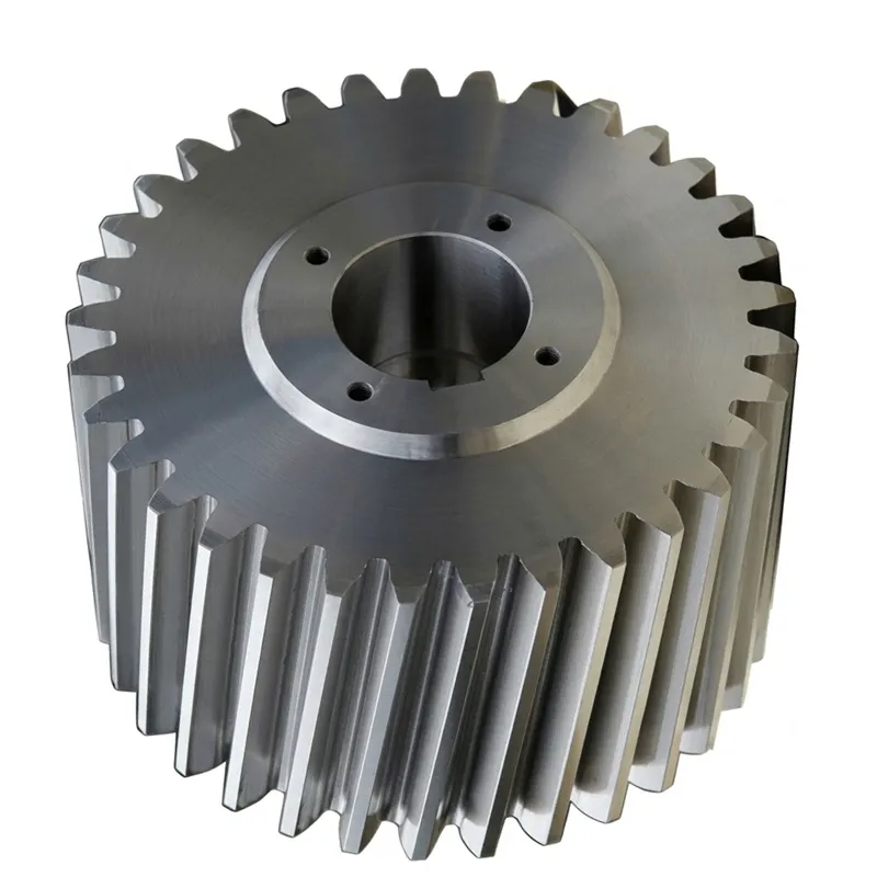
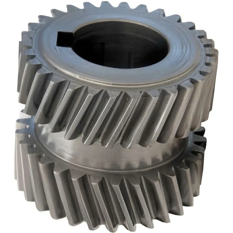
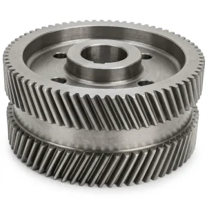
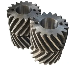
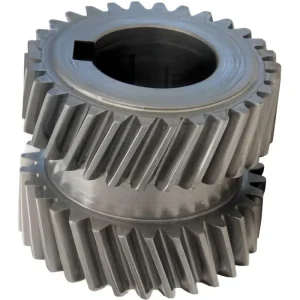
A double helical gear — sometimes called a herringbone-type gear — is a gear whose body carries two sets of helical teeth arranged in opposing directions, one left-hand helix and one right-hand helix, separated by a central groove or land. This mirror-symmetric tooth arrangement is the defining structural feature that sets double helical gears apart from every other common gear form, and it is the source of the type’s most important engineering advantage: the complete cancellation of net axial thrust at the shaft.
In a single helical gear, the angled tooth generates a force component parallel to the shaft axis as it transmits torque. This axial force must be reacted by the bearing supports, which adds to their load and complexity. In a double helical gear, the equal-and-opposite axial forces produced by the two rows of teeth cancel each other within the gear body, leaving the shaft bearings free to carry only radial loads. The result is a gear type that combines the smooth, progressive tooth engagement of helical geometry with the zero-axial-load characteristic that was previously achievable only with spur gears — while delivering substantially higher contact ratios and lower dynamic tooth forces than either.
This combination of properties explains why double helical gears are the preferred specification for the most power-intensive and precision-sensitive drive applications in the world: marine propulsion gearboxes, turbine reduction trains, rolling mill main drives, surgical robot actuators, and aerospace positioning systems all rely on double helical gearing where the engineering margins are tightest and the consequences of drive failure are most severe.
Double Helical Gear Types
Gear Type Comparison
Double Helical vs Single Helical vs Spur Gear
| Characteristic | Spur Gear | Single Helical Gear | Double Helical Gear ★ |
|---|---|---|---|
| Axial Thrust | Tiada | Significant — requires thrust bearings | None — self-cancelling |
| Contact Ratio | Low (≈1.1–1.4) | Medium (≈1.4–1.9) | High (≈2.0+) |
| Noise & Vibration | High | Sederhana | Rendah |
| Load Capacity | Piawai | Good | Highest for given diameter |
| Bearing Complexity | Simple | Requires thrust bearing | Simple — radial only |
| Manufacturing Complexity | Rendah | Sederhana | Higher — two-row hobbing |
| Terbaik Untuk | Low-speed, simple drives | Medium-power drives with space for thrust bearings | High-power, precision, and quiet drives |
Get Started
Ready to Specify Your Double Helical Gear?
Share your module, helix angle, material specification, accuracy grade, and application description. Our engineering team will respond with a detailed manufacturing proposal and — where required — a sample inspection package.
How Does a Double Helical Gear Work?
01
Progressive Tooth Engagement
Unlike spur gears that engage the full tooth width instantaneously, each helical row engages progressively from one edge across the face width. This sweeping contact distributes load gradually, reducing the dynamic force impulse at each tooth-mesh event and lowering vibration and acoustic emission across the operating speed range.
02
Self-Cancelling Axial Forces
The left-hand and right-hand helical rows generate equal axial forces in opposite directions. These forces cancel within the gear body, so the shaft and its bearings experience zero net axial load regardless of the helix angle chosen. This frees designers to select higher helix angles for improved contact ratios without any bearing penalty.
03
High Contact Ratio in Operation
With two rows of helical teeth in simultaneous engagement, the effective contact ratio is substantially higher than either spur or single helical gears of equivalent pitch. Multiple tooth pairs share the load at any instant, reducing the peak stress on each tooth flank and root, extending fatigue life, and enabling higher power densities in a given gear body size.
How to Choose the Right Double Helical Gear
DIN / AGMA / ISO / JIS Standards
OEM / ODM Custom Manufacturing
ISO 9001:2015 Certified
① Module & Tooth Dimensions
Module is the most fundamental gear parameter — it determines the tooth height, pitch, and the load a single tooth can carry. For heavy industrial drives like mill gearboxes and marine propulsion, modules of M4 to M26 or larger are typical. For precision medical and aerospace instruments, miniature modules from M0.15 to M2.0 are required. Always match the module of the double helical gear to its mating gear in the drive train — mixing modules results in incompatible tooth geometry that cannot mesh correctly.
② Helix Angle Selection
The helix angle controls the overlap ratio — the fraction of tooth face width in simultaneous contact at any instant. Higher helix angles produce smoother, quieter operation but increase the depth of the central groove required for machining clearance. For general heavy-duty drives, helix angles of 15°–30° are common. For precision instruments and low-noise requirements, 30°–45° angles may be specified. In the double helical configuration, there is no axial thrust penalty for using a higher helix angle, removing one of the key constraints in single helical gear design.
③ Material & Heat Treatment
Material choice is driven by load intensity, operating environment, and regulatory requirements. Cast steel suits large, moderately loaded gear bodies where weldability and machinability are priorities. Alloy steels (40Cr, 42CrMo, 20CrNiMo) are used where higher strength and hardenability are needed. Stainless steel is specified for corrosive, food-grade, or biocompatible environments. Heat treatment — whether carburizing, induction hardening, or quench-and-temper — determines the surface hardness and case depth that govern contact fatigue life. Never specify a surface hardness without also confirming that the core toughness is adequate for the bending stress and shock loads in the application.
④ Accuracy Grade & Certification
Accuracy grade defines the permissible deviations in tooth profile, lead, pitch, and runout — the parameters that directly affect noise, load distribution across the face width, and fatigue life. Industrial drives typically require ISO Grade 8–9 or AGMA 10–11. Precision instruments, medical devices, and aerospace actuators specify ISO Grade 5–6, DIN Grade 5–6, or AGMA Grade 12–13. Always reference the accuracy standard relevant to your market — ISO, DIN, AGMA, or JIS — and confirm that the manufacturer can provide an inspection report with actual measured values, not just a pass/fail certificate.
Where They Are Used
Double Helical Gear Application Sectors
Marine Propulsion
Ship reduction gearboxes and offshore crane drives — continuous high-power duty with zero tolerance for unplanned downtime.
Perlombongan & Industri Berat
Conveyor drives, crusher gearboxes, and mill main drives that run under extreme torque and shock loading 24 hours a day.
Power Generation
Gas turbine reduction gearboxes, wind turbine main gearboxes, and generator drive trains where bearing reliability is critical.
Medical Devices
Surgical robot actuators, infusion pump drives, and dental handpieces requiring micron-level accuracy and biocompatible materials.
Aerospace & Defence
Flight control actuators, UAV positioning systems, and military optronics with full material traceability and AS9100 documentation.
Automotive & EV
Electric vehicle powertrain gears, power steering systems, and precision subassemblies meeting IATF 16949 / TS 16949 quality requirements.