
Water & Wastewater · Drive Systems
A technical reference for process engineers, utilities procurement managers, and equipment specifiers in the United States, Australia, United Kingdom, India, and other markets designing or upgrading clarifier and thickener drive systems in municipal water and wastewater treatment facilities.
Drive System Requirements in Clarifier and Thickener Equipment
Clarifiers and thickeners are among the most continuously loaded rotating equipment in a municipal water treatment facility. A circular clarifier rotates its rake arm assembly at a speed that is slow enough to avoid disturbing the settled solids at the bottom of the tank, yet fast enough to move accumulated sludge toward the central drawoff point without allowing it to consolidate into a mass that the rake cannot penetrate. Typical rake arm rotation speeds range from 0.02 to 0.1 rpm — some of the lowest output speeds found in any industrial drive application — placing exceptional demands on the reduction ratio and on the mechanical integrity of the drive that must maintain this rotation continuously, 24 hours a day, under the variable torque loading created by changes in feed solids concentration.
The single speed reducer — specifically a worm gear speed reducer in single stage or multi-stage configuration — is the established technology for the first stage of gear reduction in clarifier and thickener center drives. Its right-angle output geometry, high gear reduction ratio per stage, and self-locking characteristic at higher ratios make it a natural fit for the slow-speed, high-torque, continuous-duty requirements of these rotating basin equipment types. Selection involves matching the required output torque, the available motor power, the structural limitations of the clarifier bridge or center column, and the maintenance access constraints of an outdoor, corrosive environment.

Struktur Pembuatan
The WP series single speed reducer uses an integral one-piece cast-iron housing that is bored and finished in a single CNC machining setup. This manufacturing approach fixes the center distance between the input worm shaft and the output wheel shaft to a dimensional tolerance that governs the gear mesh contact pattern — critical in clarifier and thickener drives that must transfer torque continuously without developing tooth contact irregularities that generate vibration in the relatively flexible drive bridge structure above an open basin.
The worm shaft and output shaft are each supported at both ends by precision rolling element bearings seated in machined bores within the housing. This dual-support arrangement manages the combined radial load from the drive chain or coupling between the reducer output and the clarifier center gear, and the axial thrust generated by the helical worm-and-wheel contact geometry. In thickener drives with heavy rake torque peaks — caused by density surges in the feed slurry — the bearing preload and housing rigidity prevent shaft deflection events that would cause momentary changes in backlash, which the clarifier torque monitoring system may interpret as a mechanical fault signal and initiate an unnecessary trip.
The WP series flange-input configurations (WPKA, WPDKA) allow a motor to be mounted directly on the reducer input face without an intermediate coupling. In clarifier drive installations on bridge structures above open basins in regions such as Australia and the United States, this compact motor-reducer package reduces the number of exposed shaft joints that require weather sealing and periodic alignment checks under outdoor operating conditions. The housing exterior carries cast ribbing that increases surface area for natural convection cooling — relevant for clarifier reducers that run continuously in direct sunlight in tropical and subtropical climates.
Sistem Bahan
Gray cast iron is the standard housing material in the WP series. In water treatment environments, cast iron provides several advantages over fabricated steel alternatives: it machines cleanly to the dimensional tolerances required for bearing bores and gear center distances, it has inherent vibration damping that attenuates the torsional pulses transferred from the drive mechanism into the clarifier bridge, and it is dimensionally stable under the temperature cycling experienced by outdoor equipment through seasonal variation — from winter sub-zero conditions in northern Europe and Canada to summer ambient temperatures above 40°C in arid regions of the Middle East and North Africa.
The worm shaft is produced from case-hardened alloy steel with a ground tooth profile. Ground worm geometry reduces sliding contact friction losses at the mesh, which is particularly relevant for clarifier drives operating at very low output speeds (below 0.5 rpm) where the sliding velocity at the worm-wheel contact is low and lubricant film thickness is more dependent on oil viscosity than on hydrodynamic wedge action. Maintaining adequate film thickness at these conditions requires a careful lubricant specification that takes into account the operating temperature range and the specific reduction ratio.
Worm wheels are cast from tin bronze or phosphor bronze. In water treatment facilities where the reducer housing is exposed to the humid, hydrogen sulfide-bearing atmosphere that can form above sludge treatment zones, bronze has a practical advantage over sintered or plastic alternatives: its corrosion resistance in moist air ensures that the wheel remains dimensionally stable even if condensation enters the housing through a degraded shaft seal. Output and input shafts are machined from medium-carbon steel with corrosion protection applied to exposed surfaces at installation — a practical consideration given the outdoor, humid-air exposure typical of water treatment plant locations in tropical regions of Southeast Asia and South America.
Recommended Model for Clarifier and Thickener Primary Drive Stage
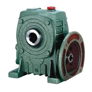
EP-WPDKA — 5 to 350 kg Single Speed Reducer
The EP-WPDKA is a double-output-shaft, flange-input single stage speed reducer suited to clarifier center drive configurations where the single reduction stage output must connect to a secondary bull gear or drive pinion on both sides of the center drive assembly. The double output shaft allows symmetric loading of the reducer body — balancing the radial forces on the output bearings — which is an advantage in clarifier drives where the output shaft connects to a center drive turntable ring gear that applies load across two diametrically opposite drive points simultaneously. The unit weight range of 5 to 350 kg spans from small thickener drives to large-diameter clarifier primary reduction stages.
| Parameter | Nilai |
|---|---|
| Unit Weight Range | 5 – 350 kg |
| Konfigurasi Output | Double output shaft |
| Input Connection | IEC motor flange (direct mount) |
| Reduction Ratio (Single Stage) | 1:10 – 1:60 |
| Frame Sizes (center distance) | 40 – 250 mm |
| Input Speed | ≤ 1500 rpm |
| Ambient Temp. Range | -40°C to +40°C |
How the Drive Chain Works in Circular Clarifiers and Thickeners
A typical circular clarifier drive consists of a motor, one or more stages of gear reduction, and a final output stage — commonly a large-diameter ring gear or a roller chain drive — that rotates the rake arm assembly. The single speed reducer occupies the first or second gear reduction stage, converting the motor’s synchronous speed (typically 1450 or 1740 rpm) to an intermediate shaft speed that feeds the final slow-speed stage. The total gear reduction from motor to rake arm may range from 1:1,000 to 1:20,000 depending on the clarifier diameter and the required rake arm rotation speed, so the worm speed reducer’s single-stage ratio of 1:10 to 1:60 represents one stage within a compound reduction arrangement rather than the complete drive in most applications.
Thickener drives follow a similar arrangement but typically operate under higher sustained torque than clarifiers of equivalent diameter, because the settled solids in a thickener are denser and more cohesive than primary clarifier sludge. The design torque for a thickener drive must account for the peak torque that occurs when a density surge arrives from the feed well and the rake arm encounters a bed of consolidated solids — a brief but high-magnitude loading event that the reducer’s bronze worm wheel and shaft bearings must absorb without fatigue damage. A service factor of 1.5 to 2.0 applied to the calculated steady-state torque is standard practice for thickener drive specifications in the mining and water treatment sectors across Australia, Canada, and South Africa.
In addition to the primary rotational drive, some clarifier designs incorporate a sludge collector drive that operates a separate sump scraper or plough mechanism at the tank floor, independent of the main rake arm rotation. These auxiliary drives operate at similarly low speeds and sustained torque but are physically smaller units located at the bottom of the center column rather than on the drive bridge above the water surface. The smallest WP series frame sizes (40–80 mm center distance) with their compact housing dimensions are applicable to these auxiliary positions without imposing structural loads on the center column that the column was not designed to carry.

Gear Reduction Reference for Water Treatment Drive Stages
The table maps the primary reducer stage parameters typical of clarifier and thickener drive applications across different equipment scales. These are representative values for the single reduction worm reducer stage only; the complete drive train includes one or more additional reduction stages to reach final rake arm speed.
| Application Type | Reducer Stage Output (rpm) | Motor Input (rpm) | Single Stage Ratio | Typical Motor Power |
|---|---|---|---|---|
| Small clarifier (up to 15 m diameter) | 20 – 50 | 1450 | 1:30 – 1:60 | 0.37 – 1.5 kW |
| Medium clarifier (15–40 m diameter) | 10 – 30 | 1450 | 1:50 – 1:60 | 1.1 – 5.5 kW |
| Large clarifier (over 40 m diameter) | 5 – 15 | 1450 | 1:60 (+ secondary stage) | 3 – 15 kW |
| Gravity thickener | 15 – 40 | 1450 | 1:40 – 1:60 | 0.75 – 7.5 kW |
| High-rate thickener / paste thickener | 10 – 25 | 1450 | 1:50 – 1:60 | 3 – 22 kW |
| Sludge scraper (auxiliary drive) | 20 – 60 | 1450 | 1:25 – 1:60 | 0.12 – 0.75 kW |
Foot-Mounted Configuration for Thickener Bridge Drive Installations
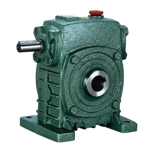
EP-WPKS — 4 to 365 kg Single Speed Reducer
The EP-WPKS is a flange-mounted, foot-base single stage speed reducer with a keyway output shaft. In thickener drive installations on bridge structures — where the reducer sits on a fabricated steel platform above the tank and connects to a secondary reduction stage via a chain and sprocket — the foot base provides positive mounting on the platform with adjustable bolt positions that accommodate minor alignment corrections without needing to shift the motor position. The large weight range of 4 to 365 kg reflects the span from small-diameter thickener primary stages through the heaviest direct-mounted configurations on large gravity thickeners in water utilities and mining operations in South Africa and Western Australia.
| Parameter | Nilai |
|---|---|
| Unit Weight Range | 4 – 365 kg |
| Input Connection | IEC motor flange or solid input shaft |
| Konfigurasi Output | Solid shaft, single or double |
| Nisbah Pengurangan | 1:10 – 1:60 |
| Bahan Perumahan | Cast iron (integral box) |

Lubrication, Sealing, and Corrosion Management
Clarifier and thickener reducers present a demanding lubrication challenge: the unit runs continuously for months or years between planned maintenance shutdowns, the output speed is so slow that hydrodynamic lubricant film formation at the worm tooth contact is minimal, and the outdoor or semi-outdoor installation often exposes the housing to temperature swings, moisture ingress, and the corrosive atmosphere present above sludge treatment basins. ISO VG 220 or VG 320 gear oil is the typical specification for the WP series in clarifier applications, with the heavier grade preferred where the ambient temperature is consistently above 25°C or where the reduction ratio places the worm sliding velocity at the low end of the hydrodynamic film-forming range.
Seal integrity is more critical in clarifier and thickener drives than in most other applications because lubricant leakage onto the drive bridge can create a slip hazard for maintenance personnel and, in wastewater treatment facilities, constitute an environmental release that triggers regulatory reporting obligations in jurisdictions such as the European Union, the United States, and Australia. The WP series standard lip seal arrangement on both the input and output shafts is appropriate for the slow shaft rotation speeds of this application. Periodic inspection of seal condition should be incorporated into the annual maintenance schedule for clarifier drives, as lip seal life under the UV exposure and temperature cycling of an outdoor installation can be shorter than under sheltered industrial conditions.
Selection Criteria for Water Treatment Drive Engineers
Design Torque and Service Factor
Clarifier torque is calculated from the rake arm geometry, solids loading, and basin diameter. Apply a service factor of 1.5–2.0 for thickeners handling variable feed density, and 1.25–1.5 for primary clarifiers with stable feed conditions. The service factor is applied at the reducer stage, not at the final output, so it must account for efficiency losses in the downstream reduction stages.
Intermediate Shaft Speed
The single speed reducer output speed feeds into the next reduction stage. Select the ratio to produce an intermediate shaft speed that the secondary stage (chain drive, helical gear, or final ring gear) can accept within its rated input speed range. Overspeeding the secondary stage input causes premature fatigue in chain links or gear teeth regardless of how correctly the worm reducer itself is sized.
Outdoor Corrosion Protection
Clarifier drives in coastal regions of the United Kingdom, the Gulf states, and tropical Asia are exposed to salt-laden or humid corrosive air. Specify surface coating or painting on exposed housing exterior surfaces at installation, protect all machined shaft surfaces with appropriate grease or coating, and ensure that the vent plug is positioned at the highest housing point and fitted with a moisture-excluding desiccant breather where the atmosphere is particularly aggressive.
Torque Overload Protection
Clarifier and thickener drives should incorporate a torque-limiting device — a shear pin coupling, a slip clutch, or an electronic torque monitoring system — upstream of the reducer. When the rake arm encounters an unexpected obstruction or a consolidated sludge bed, the overload protection activates before the torque peak can damage the bronze worm wheel or the output shaft bearings of the single speed reducer.
Maintenance Access
Clarifier bridges in municipal facilities may be narrow and exposed to weather. The selected reducer model should allow oil changes and seal inspection to be performed by two technicians using standard tools without requiring partial drive disassembly. The drain plug, fill plug, and vent plug positions must all be accessible in the installed orientation without removing the motor or uncoupling the output drive.
Weight Loading on Structure
The total weight of the motor, reducer, and associated hardware must be within the structural capacity of the clarifier bridge or center column mounting point. For large-frame reducers in the 200–365 kg range, the bridge structural assessment should be performed or reviewed by a structural engineer before specifying the drive package size, particularly for older infrastructure in developing water utilities in India and Southeast Asia where original design records may be incomplete.
Komponen Sistem Pemacu yang Serasi
The single speed reducer in a clarifier or thickener drive is one stage within a complete drivetrain. The following components are manufactured to compatible dimensional standards and are available from the same source:

Motor Elektrik
IEC-frame AC motors with B5 and B14 flange configurations mount directly onto the WP series flange-input reducer faces without an intermediate coupling. For outdoor clarifier installations in coastal or tropical regions, IP55 or IP65 rated motor enclosures provide adequate ingress protection against rain, condensation, and airborne contaminants from the treatment process. Motors are available in standard 4-pole and 6-pole configurations, and ATEX-rated versions are available for drives installed above sludge digester covers where explosive gas concentrations may be present.

Kotak Gear Cacing
Large-diameter clarifiers requiring total gear reduction ratios beyond 1:60 from a single worm stage are served by the full worm gearbox series, which includes universal and double-stage configurations providing ratios up to 1:3,600 in two worm stages. The shared housing casting standards between the single stage and multi-stage series mean that bearing and seal kits are consistent across both product families, simplifying the spare parts stock held by municipal water utilities that operate multiple clarifier units of different sizes within the same treatment facility.
Mengenai Pengilang
The production facility operates under ISO 9001:2015 certification and runs a vertically integrated manufacturing chain: raw casting, precision CNC machining, gear grinding, heat treatment, assembly, and load testing all take place under one roof. The product portfolio extends across worm gear reducers, planetary gear drives, agricultural gearboxes, power take-off shafts, hydraulic cylinders, gears, sprockets, chains, and motors — a scope that allows water utilities and equipment OEMs to source multiple drivetrain components from a single qualified supplier rather than managing separate vendor relationships for each component type.
Castings are produced in gray cast iron, ductile iron, cast steel, precision cast steel, and cast aluminum, with the material matched to the structural and environmental demands of each application. Non-standard configurations — modified shaft lengths, special bore diameters, custom mounting flanges, non-catalogue reduction ratios — are engineered alongside the standard product range to support water treatment equipment builders who need configurations outside the published catalogue.
Kedai Kerja




Soalan Lazim
Editor: PXY