
Mining & Quarrying
A technical overview of how single-speed worm gear reducers are specified, installed, and maintained across coal handling plant conveyors, stacker-reclaimer slew and travel drives, and coal preparation equipment in surface and underground coal mining operations worldwide.
Coal handling plants and stacker-reclaimer systems represent some of the most demanding continuous-duty environments for industrial drive equipment. The combination of fine coal dust — which penetrates every unsealed joint and contaminates lubricant — sustained high-torque operating profiles on conveyors running at near-full capacity for shifts on end, and the large, slow-moving drive positions on stacker-reclaimer slew rings and travelling bogies makes drivetrain specification a critical engineering decision at every plant design and refurbishment stage. Within this environment, the single speed reducer — and specifically the worm gear architecture that dominates in right-angle, high-ratio, low-to-moderate-speed drive positions — has proven its reliability across coal handling facilities in Australia, India, South Africa, and North America over decades of operational experience.
This article examines the specific drive positions within coal processing and stacker-reclaimer systems where single speed reducers are applied, the engineering rationale for their selection at each position, and the construction, material, and lubrication choices that sustain reliable performance across the extended service periods that coal handling plant operators require before scheduled overhaul. Product examples from the EP WP series single speed reducer range illustrate the performance parameters applicable to each drive category.
Drive Positions in Coal Handling Plants
A typical coal handling plant encompasses a cascade of conveyor systems, screens, crushers, sampling units, and stockpile management equipment, each with distinct drivetrain requirements. The single speed reducer appears in several of these positions as the preferred torque conversion and right-angle drive element, selected because no alternative offers the same combination of compact geometry, high reduction ratio in a single stage, inherent back-driving resistance, and simplicity of maintenance in coal-contaminated environments.
Transfer tower conveyors connecting the receiving hopper to the primary crusher typically run at moderate speed under high sustained load — the ribbon feeder below the hopper that controls coal feed rate into the crusher is almost universally fitted with a worm speed reducer because the self-locking characteristic of high-ratio worm drives prevents the loaded feeder from reversing when power is lost, removing the need for a mechanical brake on the feeder tail shaft. On the conveyor trunk lines between crusher and stock area, belt feeders and tripper car drives also employ single speed worm gear reducers for the same combination of right-angle geometry and controlled, self-locking output.
Screens in coal preparation plants — both primary sizing screens handling run-of-mine coal and product screens separating cleaned coal by size fraction — require eccentric shaft drives at 750 to 1,000 rpm from a motor typically running at 1,450 rpm on a 50 Hz supply. The single stage speed reducer at ratios of 1.5:1 to 2:1 (belt-transmitted to the screen) or a worm gear speed reducer at 10:1 to 15:1 (direct-coupled to the eccentric) serves this function. In coal preparation where water, magnetite slurry, and fine coal particles are all present in the atmosphere, the sealed housing and simple oil-bath lubrication of a single speed reducer is an operational advantage over more complex multi-stage reducers with additional sealing requirements.

Stacker-Reclaimer Drive System Architecture
Stacker-reclaimer machines at coal stockpile yards are among the most mechanically complex applications for single speed reducers because the machine contains multiple independent drive systems — the slew drive, the luffing drive, the reclaimer bucket wheel drive, the boom conveyor drive, and the travel bogies — each with different torque, speed, and duty cycle requirements, and each operating in the same fine-coal-dust and moisture-laden environment that the machine sits in permanently.
The travel bogie drive is a particularly well-suited application for a single speed worm gear reducer. The bogie drive must move the entire mass of the stacker-reclaimer along the rail track — typically at speeds of 10 to 30 metres per minute — which requires high output torque at low output speed from a compact drivetrain that fits within the bogie frame dimensions. A single stage right-angle worm-gear speed reducer paired with a standard foot-mounted induction motor satisfies all these requirements in a package that is straightforward to install and replace during scheduled maintenance outages. The self-locking property of the worm drive at high reduction ratios also provides a passive hold on an inclined rail section when the machine is parked and unpowered — a safety feature of direct practical value in coal stockpile yards where rail gradients may vary and wind load on the machine structure creates a continuous rolling force on the bogie wheels.
The luffing drive — which raises and lowers the stacker boom to adjust pile height — operates at very low speed and very high torque, making it one of the more demanding single speed reducer positions on the machine. The output speed may be as low as 0.5 to 2 rpm at the drive drum, requiring gear ratios of 60:1 or more in the single speed reducer stage, often combined with an additional reduction through the rope drum or rack-and-pinion mechanism. At these extreme ratios, the single reduction worm reducer is well within its inherent self-locking territory, meaning the boom will hold its position under gravity load when the motor is de-energised — an important safety characteristic that avoids the need for a separate mechanical arresting device on the luffing mechanism.
Manufacturing Construction
The manufacturing construction of a single speed reducer intended for coal handling and stacker-reclaimer service shares the core worm-and-wheel architecture common to all WP series products, but the selection of frame size, bearing arrangement, and sealing specification must address the specific operating conditions of a coal plant environment. Fine coal dust with particle sizes below 10 microns penetrates standard industrial seals if operating for extended periods in high-dust-concentration atmospheres, so lip seal condition and housing joint face integrity become reliability-critical maintenance items in these applications.
The worm shaft of the EP WP series single speed reducer is produced from alloy steel — typically a carburizing-grade such as 20CrMnTi — and processed through a full heat treatment sequence ending in profile grinding to achieve HRC 58–62 surface hardness at the worm thread. The profile grinding stage removes heat treatment distortion and establishes the precise involute geometry that controls the contact pattern between the worm thread and the worm wheel tooth — a parameter that directly determines the load-carrying capacity and wear rate of the reducer over its service life. For heavy-duty coal plant positions, the profile accuracy of the worm thread is as important as the material hardness; a geometrically correct contact pattern distributes load evenly across the full thread length, while a misformed contact concentrates load on a small area and produces premature wear regardless of the material quality.
The worm wheel is produced from phosphor bronze, centrifugally cast or die-cast to achieve a sound, void-free casting that minimises the risk of subsurface porosity acting as a fatigue crack initiation site under the cyclic bending load at the tooth root. The worm wheel rim is typically assembled onto a cast iron or steel hub using a shrink fit or keyed connection, separating the bronze tooth-contact material from the ferrous load-carrying hub structure. This composite construction allows the bronze rim to be replaced independently during overhaul without scrapping the entire worm wheel assembly — a maintenance cost reduction that becomes significant on the larger frame size reducers used in stacker-reclaimer travel and luffing drives.
Material System
The material system of a single speed reducer for coal processing applications must address corrosion as well as mechanical wear — a combination that is not always present in drier industrial environments but is normal in coal preparation plants where wash water, magnetite slurry, and humid mine ventilation air create conditions that attack unprotected ferrous surfaces. The standard WP series housing in close-grained cast iron (HT200) provides adequate corrosion resistance for most coal handling plant positions, but the external surface protection — whether paint system, galvanising, or epoxy coating — should be specified for the specific environment of the installation location rather than accepting a bare paint finish that may be inadequate for a coal preparation plant with high moisture levels.
Worm Shaft Steel
Case-hardening alloy steel (20CrMnTi or equivalent) provides the combination of surface hardness and core toughness required for sustained heavy-load worm shaft service. After carburizing, quenching, and grinding, the thread surface reaches HRC 58–62. The core retains ductility to absorb the shock loading from coal lump impacts transmitted back through the conveyor or feeder drive shaft into the reducer output gear. This grade is standard across all WP series single speed reducer frame sizes in coal handling service.
Applied in: WPDS, WPKA, WPKS, WPZ, WPKZ, WPDKA series
Worm Wheel Bronze
Phosphor bronze (CuSn10P) or tin bronze is the standard worm wheel material for coal handling duty. The lower hardness relative to the steel worm ensures the bronze sacrificially wears in preference to the more expensive hardened worm shaft — a deliberate design choice that concentrates wear on the more easily replaced component. The bronze’s good thermal conductivity assists heat extraction from the tooth contact zone, which is important in the high ambient temperatures of outdoor coal stockpile yard stacker-reclaimer service in Australian, Indian, and South African operations.
Applied in: All WP series models for coal plant feeder and conveyor positions
Cast Iron Housing
Close-grained grey cast iron (HT200) provides inherent vibration damping — reducing the high-frequency excitation transmitted from conveyor belt splice impacts and coal lump drop impacts into the reducer housing — while its casting capability allows complex integrated geometries including oil circulation passages, strengthened bearing boss sections, and drain/fill/breather port locations that are essential for correct lubrication management in confined plant installations where access for maintenance is restricted.
Applied in: WPKS 4–365 kg, WPDKA 5–350 kg, WPKA 5–260 kg series
Recommended Product for Coal Plant Conveyor and Feeder Drives
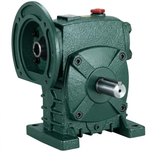
Redutor de velocidade única EP-WPDS com potência de entrada de 0,12 a 15 kW
The EP-WPDS covers an input power range from 0.12 to 15 kW, matching the motor size range found across the majority of in-plant coal handling conveyor tail drives, belt feeder drives, and auxiliary equipment positions at coal processing facilities. Its worm-and-wheel architecture provides right-angle output geometry suitable for the typical mounting arrangement of feeder and conveyor drives in coal plant transfer towers, and the sealed cast iron housing resists the coal dust ingress that would rapidly contaminate an open gear drive in the same installation position.
- Input power range: 0.12 to 15 kW
- Gear ratio range: 10:1 to 60:1 (single stage)
- Worm shaft: Case-hardened alloy steel, ground thread
- Worm wheel: Phosphor bronze or tin bronze
- Housing: Close-grained cast iron
- Lubrication: Splash lubrication, sealed oil bath
- Self-locking: Yes at high reduction ratios (above approx. 40:1)

Single Speed Reducer Positions in Stacker-Reclaimer and Coal Plant Systems
The following table maps the principal drive positions in a coal handling plant and stacker-reclaimer system to the single speed reducer specifications that typically serve them. These values are indicative ranges based on the WP series product range and standard coal handling plant engineering practice; specific applications require detailed torque and thermal calculations using the actual motor rating, required output speed, duty cycle, and ambient temperature.
| Drive Position | Typical Ratio | Input Power Range | Self-Locking Required | Duty |
|---|---|---|---|---|
| Belt feeder below hopper | 40:1 – 60:1 | 0.75 – 7.5 kW | Yes | Continuous |
| Transfer conveyor tail drive | 15:1 – 30:1 | 2.2 – 15 kW | No | Continuous |
| Coal preparation screen drive | 10:1 – 20:1 | 1.1 – 11 kW | No | Continuous |
| Stacker-reclaimer bogie travel | 40:1 – 60:1 | 1.5 – 11 kW | Yes (incline hold) | Intermittent |
| Stacker-reclaimer luffing | 50:1 – 60:1 | 3 – 15 kW | Yes (gravity hold) | Intermittent |
| Tripper car drive | 20:1 – 40:1 | 0.75 – 5.5 kW | Partial | Intermittent |
Lubrication Strategies in Coal Plant Environments
Lubrication management is more critical in coal handling and preparation plant single speed reducer installations than in most other industrial environments, for two reasons: first, the fine coal dust and moisture that permanently contaminate the atmosphere around the reducer act as lubricant contaminants whenever the oil system is opened for service; second, the continuous duty cycle of conveyors and feeders means the reducer operates at sustained load for extended periods without the recovery time that intermittent-duty applications provide, so lubricant degradation from thermal oxidation accumulates faster than in machines with significant off-load periods.
The WPZ and WPKZ single speed reducers, which span oil capacities from 0.4 to 5.2 litres, rely on splash lubrication where the worm wheel dips into the oil sump and carries oil to the worm thread on each revolution. The oil level in these units must be maintained between the minimum and maximum marks specified for the mounting orientation — which is confirmed at installation and rechecked after the first 100 hours of operation, because some initial oil absorption by the bronze worm wheel and new bearing surfaces temporarily reduces the measured sump level in the first operating period. For coal plant installations, the oil change interval should be set conservatively — no longer than 2,000 hours for mineral gear oil and up to 4,000 hours for synthetic PAO gear oil — with an intermediate oil sample taken at half the interval for particle count and viscosity measurement to detect early wear or contamination before it reaches levels that damage the tooth surfaces.
In stacker-reclaimer bogie and luffing drive positions where the reducer may be idle for periods during production halts, the lubrication system must be capable of providing adequate film to the worm-wheel mesh immediately at startup — before the oil temperature has risen to its operating level and before the oil film has been fully re-established after idle draining. Synthetic PAG gear oils have a better low-temperature viscosity characteristic than mineral oils of equivalent ISO VG grade, which means the film is thicker at cold startup — a particularly relevant property for outdoor stacker-reclaimer drives at coal ports and stockpile yards in northern Canada, northern Europe, and high-altitude South African operations where winter morning startup temperatures can be below minus 10°C.

Installation Practice and Condition Monitoring
Single speed reducer installation in coal plant positions shares the fundamental requirements of any industrial gear drive — shaft alignment to within specified tolerances, correct mounting orientation matching the oil level configuration, and accurate coupling assembly — but the coal plant environment adds specific practices that are not always observed in cleaner industrial settings. The most important of these is confirming that all housing joint faces, cover plates, shaft seal lips, and oil fill and drain plug threads are properly sealed before the reducer enters a coal-dust environment, because remedying seal failures on a reducer that has been in service in a coal plant requires cleaning the housing interior of contaminated oil and fine coal before reassembly can be effective.
For stacker-reclaimer drive positions where the reducer is mounted on a moving structure, foundation bolts should be checked for tightness at every scheduled maintenance interval — vibration from the machine travel and from the slew mechanism can gradually loosen bolted connections, and a loose mounting allows relative movement between the reducer and its base plate that disrupts shaft alignment and introduces fretting corrosion at the mounting faces. This is a more significant risk on stacker-reclaimers than on fixed conveyor drives because the machine orientation and dynamic loading direction change continuously during operation.
Oil analysis is the most cost-effective condition monitoring technique for single speed reducers in coal plant service because it provides direct evidence of worm wheel bronze wear (elevated copper in the oil), contamination (silica or coal particle count increase), and oil degradation (viscosity drop or acid number rise) — each of which can be detected and acted upon while the reducer is still in service, avoiding the unplanned downtime that a sudden tooth failure would cause on a critical coal handling conveyor. For Australian, Indian, and South African coal plants operating under continuous production pressure, planned oil sampling every 1,000 hours and a proactive replacement trigger based on copper content thresholds has demonstrably extended reducer service intervals on belt feeder and conveyor drives compared to fixed-interval replacement programmes that do not use oil analysis data.
WP Series Single Speed Reducer — Coal Plant Key Parameters
Related Drive System Components
Single speed reducers in coal handling plants are paired with electric motors on the input shaft and with driven shaft couplings, sprockets, or rope drums on the output side. Sourcing the motor and reducer together from a single supply chain reduces dimensional interface risk and simplifies the procurement process for conveyor and feeder drive assemblies at coal processing facilities.
Motores elétricos
We manufacture a full range of motores elétricos including standard TEFC induction motors, high-torque configurations, and variable-speed options that are dimensioned for direct coupling or belt drive to WP series single speed reducer input flanges across the full 0.12 to 15 kW range.

Caixa de engrenagens sem-fim
For stacker-reclaimer slew drives and other coal plant positions requiring gear ratios beyond 60:1 or double-stage reduction, our worm gearbox range provides compound reduction options up to 3,600:1 in housings designed for the dust and moisture exposure of outdoor coal stockpile yard environments.

Sobre nós
Our manufacturing range covers agricultural gearboxes, worm gear reducers, planetary drive units, PTO shafts, hydraulic cylinders, precision gears, roller chains, sprockets, pulleys, and motors — all produced under an ISO 9001:2015 certified quality management system. We design and manufacture both standard catalogue products and custom-engineered assemblies in materials including ductile iron, cast iron, cast steel, precision investment-cast steel, and cast aluminium, serving industrial and mining customers across North America, Europe, Australia, and Asia. Single speed reducer product lines span the full WP series frame range from compact 4 kg units through to 365 kg heavy-industry frames.
Our engineering team supports customers at the specification stage, reviewing application requirements including torque, speed, duty cycle, mounting orientation, ambient temperature, and environmental exposure to recommend the correct reducer frame size, gear ratio, lubrication grade, and sealing specification for each drive position in a coal handling or stacker-reclaimer system. This pre-order engagement reduces the risk of thermal underrating and mounting orientation errors that are the most frequently encountered causes of premature single speed reducer failure in coal plant service.
Oficina




Perguntas frequentes
Which single speed reducer ratio is correct for a belt feeder below a coal receiving hopper at an Australian coal terminal?▼
For a belt feeder below a coal receiving hopper at an Australian coal terminal, gear ratios in the 40:1 to 60:1 range are standard, as the feeder belt must move slowly enough to regulate the coal feed rate into the primary crusher — typically 0.05 to 0.3 metres per second at the belt surface — from a motor running at 1,450 rpm on a 50 Hz supply. At ratios above 40:1, the single speed worm gear reducer is inherently self-locking, which prevents the loaded feeder belt from reversing when power is cut, removing the requirement for a separate holding brake. When requesting a quote, provide the motor rating (kW), the required belt speed (m/s), the belt drive pulley diameter, and the peak coal load per metre of belt to allow correct thermal derating for the continuous duty profile typical of high-throughput Australian coal port operations.
How do I find a reliable single speed reducer supplier for a stacker-reclaimer bogie drive upgrade at a South African coal mine?▼
When sourcing a single speed reducer for a stacker-reclaimer bogie drive in a South African coal mine, the key qualification criteria are: ISO 9001:2015 certification covering the manufacturing process; availability of full dimensional drawings, torque capacity tables, and thermal rating data for the specific ratio and motor power needed; and application engineering support to confirm the thermal rating is adequate for the ambient temperature at the specific site. South African coal stockpile yards in the Witbank and Waterberg regions experience ambient temperatures that regularly exceed 35°C in summer, which significantly reduces the thermal headroom of the reducer relative to its nominal rated capacity — this derating must be explicitly confirmed before finalising the frame size selection.
What is the correct gear oil specification for a single stage right-angle worm-gear speed reducer on a coal preparation screen drive in India?▼
For a single stage right-angle worm-gear speed reducer on a coal preparation screen drive in India — where ambient temperatures at many preparation plants exceed 40°C during summer — ISO VG 460 gear oil is the standard specification for gear ratios in the 10:1 to 20:1 range. The higher viscosity maintains adequate film thickness at elevated sump temperatures that would reduce an ISO VG 220 oil below the minimum viscosity required for hydrodynamic film formation at the worm-wheel mesh. For continuous screen drive duty at high ambient temperature, switching to a synthetic PAO ISO VG 460 oil provides more consistent viscosity across the day’s temperature range and typically extends the oil change interval from 2,000 hours with mineral oil to 4,000–6,000 hours — a maintenance cost reduction that is particularly valuable in coal preparation plants operating multi-shift continuous production schedules.
When should a single reduction worm reducer be replaced on a coal conveyor drive in a Canadian underground mining operation?▼
For a coal conveyor single reduction worm reducer in a Canadian underground mine, planned replacement should be scheduled when oil analysis shows copper content from worm wheel bronze wear rising above the established trend baseline — typically when copper reaches 200 to 400 ppm depending on the sump volume — or when vibration monitoring detects increasing noise at the mesh frequency, or when a planned inspection at an oil change confirms visible pitting on the worm wheel tooth faces covering more than approximately 4% of the active tooth area. Running to visible tooth failure on a critical coal conveyor drive in underground service is a significantly more costly and disruptive outcome than a planned replacement at a scheduled maintenance window, where the machine can be isolated, the reducer changed, and the drive realigned without impacting the production shift schedule.
Editor: PXY