
Mining & Quarrying
A technical reference examining how single-speed reducers are specified and integrated within the auxiliary and ancillary drive circuits of SAG mill and ball mill systems in gold and copper concentrators — covering drive architecture, material requirements, lubrication strategy, and maintenance practice.
Semi-autogenous grinding (SAG) mills and ball mills are the primary ore size reduction equipment in most large-scale gold and copper concentrators worldwide. Their main drive systems — typically ring motors, synchronous motors with pinion and ring gear arrangements, or wound-rotor induction motors with liquid rheostat starting — are large engineering systems designed specifically for continuous operation at hundreds to thousands of kilowatts. However, surrounding every SAG mill or ball mill is a constellation of auxiliary and ancillary drive positions where single speed reducers perform essential functions that directly affect mill availability and grinding circuit performance: lubrication pump drives, trunnion bearing jacking oil supply, liner bolt tensioning tool drives, creep drives for liner change positioning, and feed chute actuation systems.
These auxiliary positions are frequently undersized in maintenance planning relative to their operational importance. A trunnion bearing lubrication pump failure at a large SAG mill in a Chilean copper concentrator can force a mill shutdown within minutes if the high-pressure jacking oil system cannot be re-established. A creep drive failure during a planned liner change can extend the outage by hours while the mill shell is manually positioned. Understanding which single speed reducer configurations are appropriate for each of these positions — including gear ratio, frame size, lubrication requirements, and the specific shock and thermal loading that each duty imposes — supports more reliable mill operation and better-informed procurement decisions.
Where Single Speed Reducers Appear in SAG Mill and Ball Mill Systems
Within the wider mill drive system, the single speed reducer does not typically appear in the main drive train of large SAG or ball mills — those positions are served by purpose-built girth gear drives, ring motors, or large helical reducers designed specifically for the millions of Newton-metres of output torque involved. The single speed reducer’s role is in the supporting systems: the drives that prepare the mill for operation, maintain it during operation, and enable it to be safely inspected, lined, and restarted.
The creep drive — which rotates the mill shell at very low speed (typically 0.1 to 0.5 rpm) to allow liner inspection, bolt checking, and liner plate removal and replacement — is a major application. A standard 4-pole induction motor running at 1,450 rpm must be reduced to 0.1 rpm to achieve a typical creep speed, requiring a total reduction of approximately 14,500:1. In practice, this is achieved through a combination of a worm gear speed reducer at 60:1, a secondary reduction stage, and a chain or belt final drive to the mill pinion or creep drive coupling. The single speed reducer provides the primary high-ratio reduction stage in this cascade, and the self-locking characteristic of the worm at 60:1 prevents the mill from rolling under its own mass imbalance when the creep drive is disengaged — an important safety feature during liner change operations.
Lubrication system drives are a second major application category. The high-pressure jacking oil system that lifts the trunnion bearing shell at startup uses a hydraulic power unit driven by an electric motor through a single speed worm gear reducer. The trommel screen discharge drive on a ball mill — a rotating cylindrical screen that separates ball charge from oversize material in the discharge slurry — runs at 1 to 5 rpm and is typically powered through a worm speed reducer at high ratio. Each of these positions imposes specific duty conditions on the reducer: the jacking oil unit operates intermittently and at high starting load; the trommel drive operates continuously at very low speed under a sustained load from the wet slurry weight in the rotating screen body.

Manufacturing Construction
The manufacturing construction of a single speed reducer used in SAG mill and ball mill auxiliary service must account for several operating conditions that are more demanding than typical light industrial applications. Mill auxiliary drive positions experience high vibration levels transmitted from the mill shell through the foundation structure — particularly on SAG mills where the charge impact frequency generates significant low-frequency vibration that propagates into every piece of equipment mounted on the mill platform. The reducer housing must be rigid enough to maintain bearing bore alignment under this vibration without loosening the fastening between the reducer base and its mounting platform.
The worm shaft is produced from case-hardening alloy steel — typically 20CrMnTi or an equivalent carburizing-grade steel — processed through carburizing, quenching, and profile grinding to achieve HRC 58–62 surface hardness at the worm thread flanks. Profile grinding is particularly important for mill auxiliary service because the very low output speeds typical of creep drive and trommel screen positions mean that the sliding velocity at the worm-wheel mesh is low, reducing the tendency for hydrodynamic oil film formation and making the surface finish of the worm thread a primary determinant of contact quality at the tooth mesh. A thread with 0.4 micron Ra finish distributes load more evenly across the contact area at low sliding speed than a thread finished to 0.8 micron Ra, which is why precision-ground worm shafts are specified for the high-ratio reducers used in creep drive applications rather than milled-and-hardened alternatives.
The worm wheel is cast from phosphor bronze (CuSn10P) and assembled onto a cast iron or steel hub. For the very large frame sizes used in SAG mill main ancillary positions, centrifugal casting of the bronze rim produces a more uniform microstructure — with fewer casting porosity defects — than static casting, which is important because subsurface porosity in the bronze can become the origin of fatigue cracking under the sustained cyclic load of continuous creep drive or trommel screen operation. The hub-to-rim fit must maintain adequate contact pressure under the thermal cycling that occurs between cold-startup and warm equilibrium conditions in outdoor concentrator environments in the Atacama desert in Chile or the Pilbara in Western Australia, where diurnal temperature swings exceed 30°C.
Material System
The material system for single speed reducers in gold and copper concentrator mill auxiliary service spans the same worm shaft steel, worm wheel bronze, and cast iron housing materials as other heavy mining applications, but the specific duty conditions of mill service — very high ratio operation, outdoor high-ambient-temperature exposure, and long unattended running intervals — each introduce particular requirements that influence how the standard material system is specified.
Worm Shaft: Case-Hardened Alloy Steel
After carburizing and profile grinding to HRC 58–62, the worm thread provides contact fatigue resistance under the high Hertzian pressures generated at the mesh even at the low sliding velocities typical of high-ratio creep drive operation. The precision-ground thread profile is more critical in mill auxiliary applications than in standard conveyor drives because the low sliding speed reduces the oil film parameter, making surface finish the primary factor controlling whether asperity contact — and the associated adhesive wear — occurs at the worm-wheel tooth face.
Applied across all WP series frames in mill auxiliary service
Worm Wheel: Phosphor Bronze (CuSn10P)
Centrifugally cast phosphor bronze is standard for the larger frame sizes used in SAG mill creep drives and trommel screen positions. Its lower hardness than the steel worm concentrates wear on the replaceable bronze component, and its good corrosion resistance suits outdoor concentrator environments where the reducer housing may be exposed to the cyanide-containing slurry mist and wash water present around gold mill discharge areas. Phosphor bronze tooth surfaces also have a lower coefficient of friction against hardened steel than most alternative materials, reducing the friction-generated heat at the mesh that would otherwise accumulate during extended low-speed operation.
Centrifugally cast for WPKS 4–365 kg and WPDKA 5–350 kg large frames
Housing: Grey Cast Iron with Surface Protection
The standard HT200 grey cast iron housing provides adequate structural rigidity for the bearing bore alignment required in high-ratio mill auxiliary drives and inherent vibration damping that is genuinely useful on a mill platform where foundation vibration is continuous during operation. For outdoor concentrator installations exposed to the sodium cyanide mist and acidic process water of gold concentrators — particularly in West African and Australian gold processing operations — an epoxy or polyurethane external coating over the standard primer provides a longer interval before surface corrosion compromises the housing joint face integrity and creates oil leakage paths.
Sealed for splash lubrication in multiple mounting orientations
Gear Ratio Requirements Across Mill Auxiliary Drive Positions
The gear ratio requirements for different SAG mill and ball mill auxiliary drive positions span a wider range than most other mining applications, and the selection of the correct single stage speed reducer ratio at each position is more consequential than in applications where the driven equipment is tolerant of modest speed variations. The following table provides guidance on the reducer ratio ranges applicable to the principal mill auxiliary drive positions in gold and copper concentrator mill systems.
| Drive Position | Target Output Speed | Single Reducer Ratio | Self-Locking Needed | Duty |
|---|---|---|---|---|
| Creep drive (liner change) | 0.1 – 0.5 rpm at mill shell | 60:1 (cascade stage 1) | Yes — mill position hold | Intermittent |
| Trommel screen drive | 1 – 5 rpm | 20:1 – 60:1 | No | Continuous |
| Lubrication pump drive | 750 – 1,450 rpm | 1:1 or low reduction belt | No | Intermittent (startup) |
| Feed chute actuator | 5 – 20 rpm at actuator | 30:1 – 60:1 | Yes — position hold | Intermittent |
| Discharge conveyor (short) | Drive pulley as required | 15:1 – 40:1 | No | Continuous |
Recommended Product for Mill Auxiliary Drive Applications
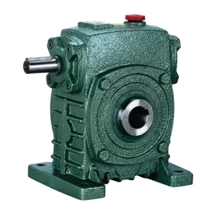
EP-WPKS 4–365 kg Single Speed Reducer
The EP-WPKS series spans a frame weight range of 4 to 365 kg — the widest weight range in the WP product line — which corresponds to the torque and frame size range needed across the diverse single speed reducer positions in a large SAG mill or ball mill ancillary drive system. At the lower frame sizes it serves trommel screen and feed chute actuator positions; at the larger frames it accommodates the high-ratio, high-torque output requirements of cascade creep drive stage reducers. The cast iron sealed housing, profile-ground worm shaft, and phosphor-bronze worm wheel meet the combined demands of precision ratio, self-locking at high ratios, and resistance to the gold and copper concentrator plant environment.
- Frame weight range: 4 to 365 kg
- Gear ratio range: 10:1 to 60:1 (single stage)
- Worm shaft: Case-hardened alloy steel, profile ground
- Worm wheel: Centrifugally cast phosphor bronze
- Housing: Grey cast iron, sealed, multi-orientation
- Self-locking: Yes at ratios above approx. 40:1
- Suitable for creep drive primary stage and trommel screen service

Lubrication at Very Low Output Speeds
The most challenging lubrication condition for a single speed reducer in a mill auxiliary drive system occurs in very high-ratio positions — creep drive primary stages and trommel screen drives — where the output speed is below 5 rpm. At these speeds, the sliding velocity at the worm-wheel mesh is very low, which reduces the tendency for the oil film to be drawn into the contact zone hydrodynamically. In the absence of a full hydrodynamic film, the tooth surfaces operate in a mixed or boundary lubrication regime where the oil viscosity, the extreme-pressure (EP) additive activity, and the surface roughness of the worm thread and wheel tooth face all determine whether metal-to-metal contact — and the adhesive wear it causes — occurs at the mesh.
For very high-ratio, very-low-speed single speed reducer positions in SAG mill and ball mill ancillary service, ISO VG 680 gear oil with an active sulphur-phosphorus EP additive package is the standard specification. The high viscosity maintains adequate oil body at the contact even without hydrodynamic entrainment, and the EP additives form sacrificial reaction layers on the tooth surfaces at the asperity contact points that prevent metallic adhesion even when the film is locally insufficient. For outdoor mill installations in high-ambient-temperature concentrator environments — copper mines in northern Chile, gold operations in the Atacama and Pilbara regions — synthetic PAG ISO VG 680 provides significantly better viscosity at the elevated sump temperatures these environments generate than a mineral oil of the same ISO VG grade, and is increasingly the default specification for new-build SAG and ball mill auxiliary drive systems in these regions.
Oil level management in mill auxiliary reducers is more critical than in standard industrial applications because the very low output speeds mean that the worm wheel’s dip into the oil sump — the mechanism that carries oil to the worm thread in splash lubrication systems — happens very infrequently. In a trommel drive reducer with a 5 rpm output, the worm wheel completes only 5 revolutions per minute, meaning each point on the worm wheel rim contacts the oil sump only once every 12 seconds. If the oil level is low, the wheel may not contact the sump at all on each revolution, leaving the worm thread unlubricated for extended periods. Regular oil level checks — at least monthly for outdoor mill service positions — are essential for this reason.
Thermal Rating and Shock Load Considerations
The thermal rating of a single speed worm gear reducer — the continuous power it can dissipate as heat through the housing surface and the oil into the surrounding air — is a frequently overlooked specification dimension in mill auxiliary drive procurement. Because mill auxiliary reducers are selected based on the peak torque of the connected load, engineers sometimes select the smallest frame that meets the mechanical torque requirement without checking whether that frame’s thermal capacity is adequate for the duty cycle of the application. In intermittent-duty positions — creep drive, feed chute actuator — thermal rating is rarely the binding constraint because the off-load cooling period is long relative to the operating period. In continuous-duty positions — trommel screen drives at gold mill discharge — the thermal rating may be the binding constraint, particularly at high ambient temperatures.
The shock load characteristic of SAG mill and ball mill auxiliary drive systems is generally moderate compared to primary crusher or vibrating screen drives, but two positions present higher shock: the creep drive engages the mill pinion or creep coupling under a load condition where the mill charge has settled asymmetrically during shutdown, creating a torque spike at engagement that the reducer must absorb without tooth damage; and the trommel screen drive may see periodic load spikes when large rocks or ball fragments lodged in the trommel apertures are suddenly dislodged, releasing a brief overload to the drive shaft. Selecting a single speed reducer with a service factor margin of at least 1.5 over the calculated steady-state torque provides adequate shock absorption capacity for both of these conditions.
In SAG mill and ball mill concentrator environments in Canada, Australia, and southern Africa, the ambient temperature at the outdoor mill platform varies significantly between seasons and between night and day. A reducer that operates satisfactorily at 25°C ambient during a temperate-season day may be near its thermal limit at 45°C on a summer afternoon at an Australian gold mine. Confirming the thermal rating at the maximum expected ambient temperature — not the average — and selecting one frame size larger than the calculated minimum if the thermal margin is less than 20% at maximum ambient is a practical engineering safeguard for concentrator mill auxiliary drive positions.

WP Series Single Speed Reducer — Mill Auxiliary Drive Parameters
Compatible Drive System Components
SAG mill and ball mill auxiliary drive systems integrate the single speed reducer with electric motors, chain drives, and flexible couplings. Sourcing the reducer and motor from the same supply chain eliminates dimensional interface uncertainty and simplifies spare parts inventory for mill site maintenance teams, where the breadth of equipment types on a large concentrator plant already creates significant parts management complexity.
Motores elétricos
We manufacture motores elétricos in TEFC and other enclosure types rated for the outdoor concentrator mill platform environment, dimensioned for direct coupling or V-belt drive to WP series single speed reducer input shafts across the power range applicable to mill auxiliary drives. Flameproof and increased-safety rated motors are available for applications where underground or explosive atmosphere ratings are required.

Caixa de engrenagens sem-fim
For creep drive cascade arrangements requiring reduction ratios beyond 60:1 from a single stage, our caixa de engrenagens sem-fim range provides double-stage and compound configurations that extend the available reduction to 3,600:1, covering the full range of creep speeds required for different SAG mill shell diameters and liner change procedural requirements at gold and copper concentrators worldwide.

Sobre nós
With more than a decade of mechanical engineering and manufacturing experience, our ISO 9001:2015 certified facility produces worm gear reducers, agricultural gearboxes, planetary drives, PTO shafts, hydraulic cylinders, precision gears, roller chains, sprockets, and motors for industrial, mining, and agricultural customers across North America, Europe, Australia, and Asia. Standard catalogue products and custom-specification assemblies are both produced in-house, using materials including cast iron, ductile iron, cast steel, precision investment-cast steel, and cast aluminium, to the dimensional and performance specifications required by each application.
Our engineering team supports concentrator mill customers at the specification stage — reviewing creep drive ratio cascades, thermal ratings for high-ambient-temperature outdoor mill platforms, and lubrication grade selection for very-low-speed trommel and feed chute actuator positions — so that the single speed reducer specified for each mill auxiliary drive position is correctly matched to its actual duty conditions rather than simply to its nominal load torque.
Oficina



Perguntas frequentes
What single speed reducer configuration is correct for the creep drive primary stage of a SAG mill at a Chilean copper concentrator, and how do I get a quote?▼
For the primary stage of a SAG mill creep drive at a Chilean copper concentrator, a single speed worm reducer at 60:1 is the standard first stage in a cascade reduction from motor to mill shell. To specify this correctly and request a quotation, provide the motor frame and shaft dimensions, the required output torque at the 60:1 stage output, the ambient temperature at the mill platform level (relevant for thermal rating confirmation at Atacama and Andean altitude sites), and the mounting orientation of the reducer within the creep drive assembly. The supplier should confirm both the mechanical torque capacity and the self-locking rating — the self-locking characteristic at 60:1 is essential for mill shell position holding during liner change, and should be explicitly specified rather than assumed from the ratio alone.
How often should the gear oil be changed in a single stage speed reducer driving a trommel screen at an Australian gold concentrator?▼
For a trommel screen single stage reducer at an Australian gold concentrator — particularly at outdoor mill sites in the Pilbara or Kalgoorlie regions where ambient temperatures at the mill platform can reach 45–50°C in summer — gear oil condition monitoring rather than fixed-interval replacement is the recommended approach. With mineral ISO VG 680 oil, an initial change at 500 hours followed by changes at 2,000-hour intervals, with quarterly oil samples for viscosity, particle count, and copper content analysis, provides a reliable maintenance framework. Switching to a synthetic PAG ISO VG 680 extends the interval to 4,000–6,000 hours while maintaining better viscosity at elevated sump temperatures. The low output speed of the trommel reducer (1–5 rpm) means the oil temperature does not rise as dramatically as in higher-speed drives, but the outdoor ambient temperature exposure is the dominant thermal factor for these surface-mounted mill auxiliary units.
Which worm gear reducer frame size is appropriate for a ball mill trommel screen drive at a South African gold mine?▼
Frame size selection for a ball mill trommel screen drive at a South African gold mine requires calculating the output torque from the trommel screen’s mass and diameter, the friction coefficient at the drive rim, and the required drive speed, then applying a service factor of at least 1.5 for the shock loading from material lodged in screen apertures. The thermal rating of the selected frame must then be confirmed for continuous duty at the maximum ambient temperature at the outdoor mill platform — in the Witwatersrand and Limpopo gold mining regions, ambient temperatures of 35–40°C are common during the summer production season, which requires a thermal derating of approximately 10–15% from the rated thermal capacity stated at 20°C ambient. Request from the supplier both the mechanical torque table and the thermal rating derating curves at actual ambient temperature as part of the technical data package for the quotation.
Editor: PXY