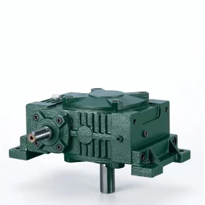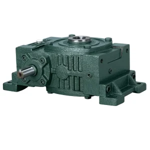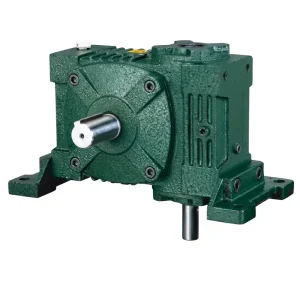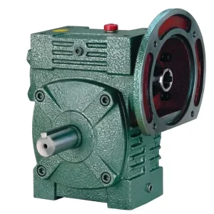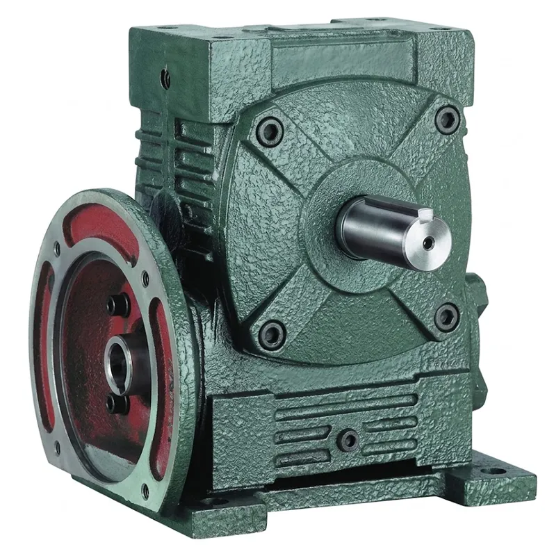
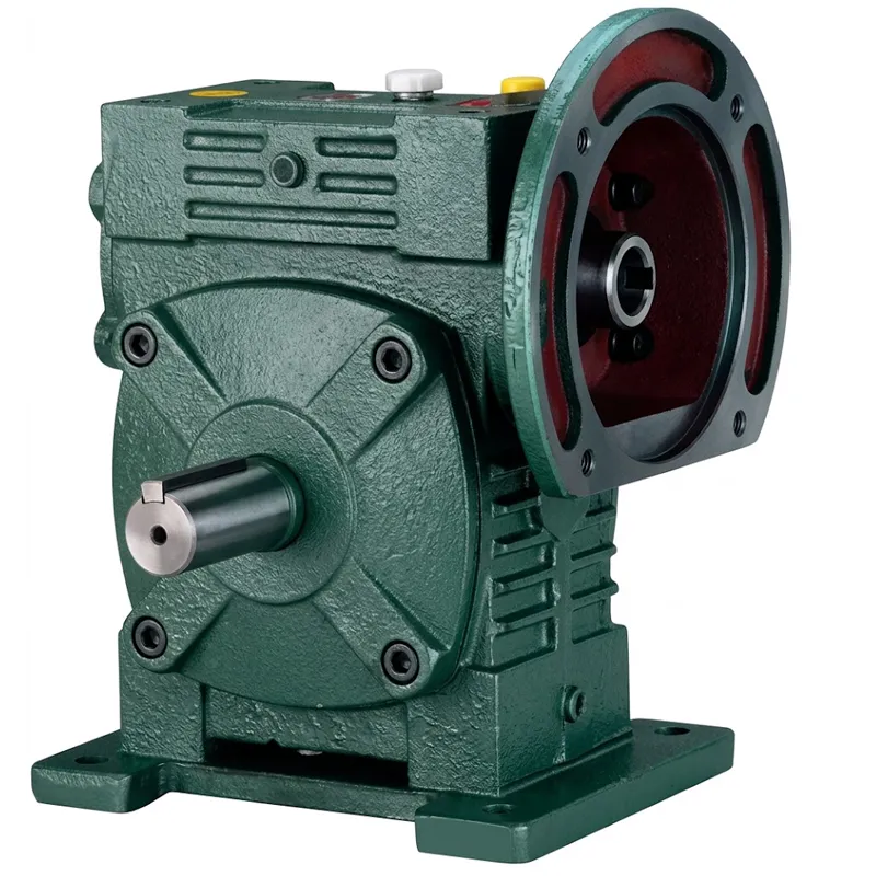
EP-4 to 376 kg WPWDS-A Universal Speed Reducer
The EP-WPWDS-A series comprises universal worm gear reducers available in WPWDS and WPWDA configurations, designed for direct motor integration. Covering sizes 40 to 250, these units support power inputs from 0.12 kW to 15.0 kW with reduction ratios ranging from 1/5 to 1/60. Weighing between 5 kg and 395 kg, they feature robust cast iron housings and versatile shaft direction options (A-F) to accommodate complex layouts. Key specifications include motor flange compatibility up to M16 and output shafts up to 25×9 mm. This series ensures reliable torque transmission and compact design, making it ideal for industrial machinery requiring precise speed control and efficient direct-drive capabilities in space-constrained environments.
EP-WPWDS-A Universal Speed Reducer — 4 to 376 kg Series
O EP-WPWDS-A universal speed reducer is a heavy-duty, flange-mounted worm gear speed reducer engineered for consistent torque transmission across a wide spectrum of industrial applications. Available in frame sizes from 40 to 250, with weight ratings spanning 4 kg to 395 kg, this universal speed reducer delivers the kind of reliable, low-noise performance that continuous-duty operations demand. Whether you are outfitting a conveyor system in a warehouse, driving a mixing unit in a processing plant, or powering hoisting equipment on a construction site, the WPWDS-A series offers the mechanical precision and long service life your equipment deserves.
Built around proven worm-and-wheel geometry, the EP-WPWDS-A universal speed worm reducer achieves reduction ratios from 1/5 through 1/60, making it one of the most versatile worm drive speed reducers available for both OEM integration and field replacement. Every unit ships fully assembled, oil-filled, and ready to mount — keeping your commissioning time short and your uptime high.
Technical Specifications — WPWDS-A Series Universal Speed Reducer
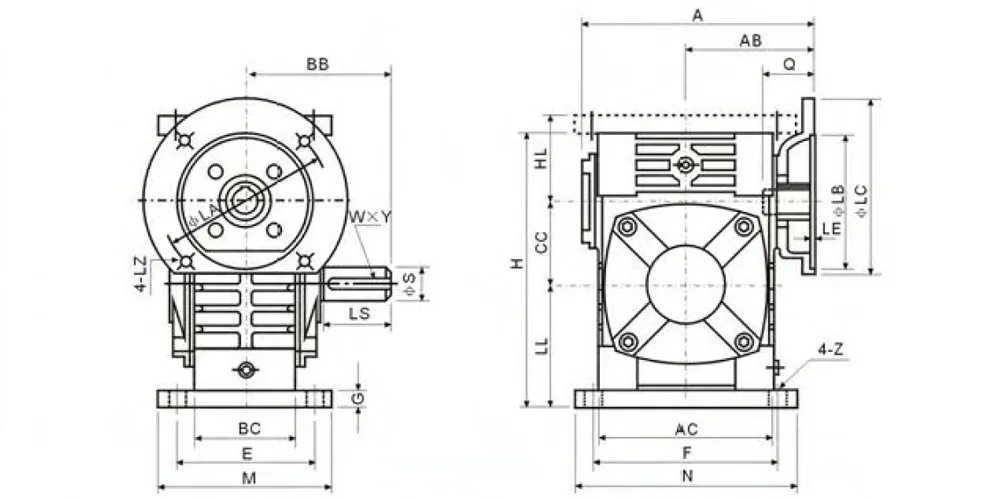
The table below covers the complete dimensional and rating data for each frame size in the EP-WPWDS-A universal speed reducer family. All linear dimensions are given in millimetres (mm); weight in kilograms (kg). Input power ratings apply at the specified reduction ratio at 1400 rpm input speed with a service factor of 1.0. For applications with shock loading or duty cycles exceeding 10 hours per day, please apply the appropriate service factor and select the next larger frame size accordingly.
| Tamanho | Input (kW) | Razão | UM | AB | BB | AC | BC | H | HL | LL | Output
Shaft W×Y |
Input
Hole T×V |
Flange
Bolt |
LS | S | Weight
(kg) |
|---|---|---|---|---|---|---|---|---|---|---|---|---|---|---|---|---|
| 40 | 0.12 | 1/5–1/60 | 135 | 75 | 74 | 95 | 61 | 60 | 45 | 135 | 28×14 | 4×12.8 | M8 | 31 | 11 | 5 |
| 50 | 0.18 | 1/5–1/60 | 151 | 83 | 97 | 111 | 68 | 80 | 50 | 165 | 40×17 | 4×12.8 | M8 | 31 | 11 | 8 |
| 60 | 0.37 | 1/5 | 167 | 91 | 112 | 127 | 76 | 93 | 60 | 195 | 50×22 | 5×16.3 | M8 | 33 | 14 | 12.5 |
| 70 | 0.37 / 0.75 | 1/10 | 200 | 109 | 131 | 152 | 86 | 108 | 73 | 233 | 60×28 | 5×16.3 | M8 | 40 | 14 | 17 |
| 80 | 0.75 / 1.5 | 1/15–1/20 | 225 | 125 | 142 | 169 | 102 | 123 | 83 | 268 | 65×32 | 6×21.8 | M10 | 48 | 19 | 26 |
| 100 | 1.5 | 1/25 | 280 | 148 | 169 | 216 | 117 | 150 | 100 | 330 | 75×38 | 8×27.3 | M10 | 52 | 24 | 41.5 |
| 120 | 2.2 / 3.0 | 1/30 | 333 | 181 | 190 | 256 | 124 | 180 | 120 | 395 | 85×45 | 8×31.3 | M12 | 63 | 28 | 60 |
| 135 | 3.0 / 4.0 | 1/40 | 375 | 202 | 210 | 296 | 147 | 215 | 135 | 455 | 95×55 | 8×31.3 | M12 | 63 | 28 | 90 |
| 155 | 5.5 | 1/50 | 448 | 247 | 252 | 345 | 185 | 235 | 155 | 493 | 110×60 | 10×41.3 | M12 | 83 | 38 | 118 |
| 175 | 5.5 / 7.5 | 1/60 | 481 | 262 | 255 | 374 | 192 | 260 | 175 | 558 | 110×65 | 10×41.3 | M12 | 83 | 38 | 167 |
| 200 | 11.0 | 1/40–1/60 | 543 | 285 | 319 | 412 | 230 | 290 | 200 | 620 | 125×70 | 12×45.3 | M16 | 114 | 42 | 237 |
| 250 | 11.0 / 15.0 | 1/50–1/60 | 615 | 330 | 385 | 500 | 285 | 350 | 250 | 750 | 155×90 | 12×45.3 | M16 | 114 | 42 | 395 |
All dimensions in mm. Weight in kg. Scroll horizontally on mobile to view all columns.
Five Key Advantages of the EP-WPWDS-A Universal Speed Reducer
Reduction ratios of 1/5, 1/10, 1/15, 1/20, 1/25, 1/30, 1/40, 1/50, and 1/60 are available within a single product family. That range means you can select the exact output speed your process requires without resorting to external chain stages or supplementary gearboxes — a genuine advantage when space is at a premium or when system complexity must be minimized.
At higher reduction ratios the worm-and-wheel geometry becomes inherently self-locking, preventing back-drive under load. This characteristic eliminates the need for separate mechanical braking devices on vertical lifts, inclined conveyors, and positioning tables — reducing component count, purchase cost, and routine maintenance intervals without sacrificing safety or holding precision.
The WPWDS-A universal speed reducer configuration integrates a motor-mounting flange directly onto the gearbox housing. Pairing the reducer with a matching electric motor creates a clean, co-axial drive module that bolts straight onto your machine frame. The foot-and-flange combination accommodates multiple mounting orientations, enabling flexible installation even in retrofit scenarios where access is restricted.
Frame sizes 40 through 250 cover an output weight capacity from 4 kg to 395 kg, making the EP-WPWDS-A series universal speed reducer genuinely useful across both light packaging lines and large heavy-duty worm drive gearbox applications. The cast iron housing resists vibration-induced cracking, damps operational noise effectively, and provides the dimensional stability required to maintain precise gear mesh geometry throughout years of continuous service.
Six shaft direction configurations — designated A through F — are available as standard options. Whether your driven machine requires an input and output on the same axis, a right-angle arrangement, or a double-output layout, the EP-WPWDS-A universal speed worm gear reducer can be specified to match without custom engineering work. This flexibility reduces lead times and simplifies inventory management for multi-machine production facilities.
How Does a Worm Gear Reducer Work?
At its core, a worm gear speed reducer translates high-speed rotational input into low-speed, high-torque output through the meshing of a helical worm shaft against a bronze or brass worm wheel. The worm — driven by the motor — wraps around the wheel at a precise lead angle. Because each revolution of the worm advances the wheel by only one or a few teeth, large speed reductions are achieved in a physically compact stage. The worm gear reduction ratio is determined by dividing the number of teeth on the wheel by the number of starts (thread leads) on the worm.
Do worm gears reduce speed? Absolutely — and that is their primary purpose. The 90-degree shaft angle between worm and wheel also means the assembly fits neatly into corner-drive arrangements that would otherwise require bevel gearing. In the EP-WPWDS-A universal speed reducer design, input enters through the hardened worm shaft, energy transfers via the sliding-contact mesh, and the output shaft delivers smooth, vibration-dampened torque to your driven equipment.
The purpose of the gear reducer in any drive train is straightforward: match the high-speed, low-torque output of a standard motor to the low-speed, high-torque requirement of the actual process load. A correctly sized worm drive reducer eliminates the need for oversized motors, reduces mechanical stress on downstream components, and extends the service life of the entire drivetrain.

Universal Speed Reducer Materials & Build Quality
The EP-WPWDS-A universal speed reducer is constructed from carefully selected materials chosen to maximise both strength and longevity under industrial operating conditions. The main housing is cast from high-grade cast iron (HT200 or equivalent), which combines excellent compressive strength with inherent vibration absorption — critical for maintaining quiet, stable operation across shift-long duty cycles.
The worm shaft is precision-machined from 20CrMnTi alloy steel, carburized and quenched to surface hardness of HRC 58–62. This treatment creates a hard, wear-resistant contact surface while preserving a tough, impact-absorbing core — preventing sudden brittle fracture even under momentary overload. The worm wheel is cast from high-phosphorus bronze (ZCuSn10Pb1 or similar), a material known for its excellent compatibility with steel in sliding contact, resulting in lower friction coefficients, reduced heat generation, and a much longer mesh service life than ferrous wheel materials.
Input and output shafts are supported on double-row or paired angular-contact rolling bearings, pre-loaded and sealed to keep lubricant in and contaminants out. Oil seals at every shaft penetration meet IP55 ingress protection as standard, with IP65 available on request for washdown or outdoor environments. Synthetic gear oil (ISO VG 220 or 460) is supplied pre-filled; the sealed-for-life option eliminates scheduled oil changes entirely.

Universal Speed Reducer Application Scenarios
The EP-WPWDS-A universal speed reducer is a genuinely adaptable solution. Its combination of wide ratio selection, compact envelope, and robust build makes it suitable for a remarkable variety of industrial sectors globally — from food and beverage processing lines in Europe and North America to agricultural equipment manufacturing across Southeast Asia and South America. Below are the primary application categories where this large universal speed reducer or replacement universal speed reducer consistently delivers measurable value.
Conveyor & Material Handling
Belt conveyors, slat conveyors, roller tables, and chain-driven transfer systems all benefit from the smooth, regulated output speed this worm speed reducer gear box provides. The self-braking property at higher ratios eliminates runback on inclined sections, reducing the need for ancillary holding brakes and lowering overall system cost.
Packaging Machinery
Filling machines, capping heads, label applicators, and cartoning lines demand precise, repeatable speed control. The new universal speed reducer WPWDS-A series delivers consistent output shaft speed regardless of minor load fluctuations, making it a preferred worm reducer gear box choice for OEMs supplying the global packaging sector.
Agricultural Equipment
Grain augers, seed drills, feed mixers, and irrigation drive heads often operate in dusty, vibration-intensive environments. The sealed, powder-coated housing of the EP-WPWDS-A withstands these conditions reliably. This makes it a well-regarded electrical motors universal speed worm reducer pairing option for agricultural OEMs targeting markets across Australia, Brazil, and the Netherlands.
Hoisting & Lifting
Small and medium hoists, winches, and scissor lifts frequently specify high torque worm gearbox configurations at 1/40 to 1/60 ratios. The inherent load-holding characteristic means the load stays in position without power — a fundamental safety requirement that architects and compliance engineers across the UK and Canada specify as standard.
Mixing & Agitation
Paddle mixers, ribbon blenders, and tank agitators in chemical, food, and pharmaceutical plants need steady, low-speed torque over extended duty cycles. The EP-WPWDS-A worm gear reducer motor pairing sustains continuous full-load output without thermal shutdown, provided the operating environment remains within the unit's rated ambient temperature range.
Gate & Valve Actuation
Water treatment plants, irrigation infrastructure, and pipeline control stations use worm drive reducer assemblies to operate large gate valves and sluice gates manually or via motor drive. The compact size universal speed reducer configuration fits neatly within existing valve actuator housings, simplifying retrofit and replacement universal speed worm reducer projects globally.
Worm Gear Reducer Installation Guidelines
Correct worm gear reducer installation is critical to achieving rated service life and maintaining the manufacturer's performance guarantees. The following steps reflect standard mechanical best practice and apply to all frame sizes in the WPWDS-A series.
- Verify that the mounting base is flat and rigid — any twist or flex will misalign the output shaft and accelerate bearing wear prematurely.
- Use a flexible coupling or direct-drive bell-housing connection between the motor and the reducer input flange; avoid rigid couplings unless perfect coaxial alignment can be confirmed with a dial indicator.
- Check the oil level via the inspection plug before first start-up; the unit ships with oil but transit handling may affect the level.
- Ensure adequate ventilation around the housing — particularly at the top breathing plug — to prevent pressure build-up and oil leakage at seals during extended duty cycles.
- For the first 100 hours of operation, inspect for unusual vibration or temperature rise at each maintenance interval; adjust output shaft radial load if necessary to keep it within the catalogue limit.
For detailed worm gear reducer installation drawings and clearance requirements, consult the dimensional table above and the shaft direction diagram (configurations A through F). Our technical support team can assist with selection and worm reducer motor pairing calculations for any specific duty point.
Produtos relacionados e compatibilidade do sistema
The EP-WPWDS-A universal speed reducer is designed as part of a complete drive system. Pairing it with the correct motor and the right companion gearbox series ensures optimal efficiency, simplified sourcing, and one-stop supply chain convenience for OEMs and end-users worldwide.

IEC-frame Motores elétricos mount directly to the WPWDS-A universal speed reducer input flange, eliminating shaft couplings and reducing the overall drive unit length. Our range covers outputs from 0.12 kW through 15 kW, matching every frame size in this universal speed reducer series for a fully integrated, single-source supply.

If the WPWDS-A universal speed reducer does not match your exact mounting requirement, explore our complete Caixa de engrenagens sem-fim range — including NMRV, WP, and RV series units. Every model is built to the same quality standards and is compatible with the same motor flange interfaces, making cross-series design-in straightforward for engineers specifying multi-speed production lines.
About Us — 10+ Years of Mechanical Transmission Expertise
With over a decade dedicated to mechanical power transmission engineering, our production team has built a reputation for consistent quality across agricultural gearboxes, worm gear reducers, planetary gear drives, PTO shafts, hydraulic cylinders, gears, chains, and motors. Our facility holds ISO 9001:2015 certification — a commitment to systematic quality management that governs every stage of the manufacturing process, from raw material inspection through final dimensional check and test run.
We design and manufacture an extensive range of industrial and agricultural gearboxes and drive assemblies in ductile iron, cast iron, cast steel, precision cast steel, and cast aluminium. Our in-house machining capabilities extend to gears, sprockets, worm gears, pulleys, worms, shafts, and both standard and bespoke mechanical components — enabling us to supply complete drive solutions from a single source rather than requiring customers to coordinate across multiple vendors. For engineers searching for a premium worm reducer or a white universal speed worm reducer for specific ambient conditions, our engineering team can advise on material and surface finish options without extended lead times.
Oficina




Perguntas frequentes
Editor: PXY