
Wastewater Treatment · Drive Technology
A technical reference for drive engineers and plant operators covering worm gear reducer construction, corrosion resistance, torque characteristics, and product selection for municipal and industrial wastewater treatment installations worldwide.
Wastewater treatment plants demand drive components that perform without interruption across applications characterised by slow output speeds, high torque at low rotational velocity, and continuous exposure to wet, corrosive, and biologically active environments. Sludge scrapers in primary and secondary clarifiers rotate the collector bridge and rake arms at speeds as low as 0.5 to 5 RPM over basins that may span 40 metres or more in diameter. Surface aerators and submerged aerator drives work against the drag forces of mixed liquor in aeration tanks, often running 24 hours a day throughout the year. Both applications place their drive components under sustained mechanical and environmental stress that generic industrial gearboxes are not designed to manage reliably.
The single speed reducer based on worm gear technology is the established drive solution for sludge scraper and aerator duties in treatment plants ranging from small municipal facilities to large-scale industrial effluent treatment installations. The single stage right-angle worm-gear speed reducer achieves the very high reduction ratios needed to bring standard motor speeds down to the creeping output speeds that scraper bridges and aerator impellers require, within a compact housing that fits the constrained drive bays on clarifier bridge structures and aerator float frames.
This article covers the mechanical design and material selection of WP-series single speed reducers in the context of wastewater treatment, traces specific performance requirements through sludge scraper and aerator applications, and provides selection guidance supported by a product specification table. Geographic references to North American, European, and Asian treatment plant practice are included where environmental conditions influence product selection.

Manufacturing Structure of the WP-Series Single Speed Reducer
The WP-series single speed reducer is constructed around a single-piece integrally cast housing that encloses the worm shaft and worm wheel in a right-angle arrangement. Casting the housing as one component rather than assembling it from bolted halves ensures that the bearing bores for both the input worm shaft and the output shaft are machined in a single fixturing operation. The dimensional accuracy achieved this way — bore-to-bore perpendicularity, concentricity, and surface finish — is more consistent than any split-housing design where the parting plane introduces an alignment variable that depends on assembly quality at every rebuild. In wastewater treatment environments where the reducer on a scraper bridge may remain in position for years between planned maintenance shutdowns, the stability of an integral casting maintains gear mesh and bearing alignment throughout the service interval without adjustment.
The worm shaft is supported at both ends in a straddle-mounted bearing arrangement, distributing the radial and axial loads symmetrically across two bearing positions. This is significant for scraper bridge drives, where the long arm moments generated by the rotating bridge and rake structure impose steady radial loads on the output shaft that are transmitted through the output shaft bearings into the housing. The straddle support on the worm shaft absorbs the reaction without concentrating stress at a single bearing, maintaining gear mesh geometry and avoiding premature bearing failure during the slow continuous rotation that scraper drives demand.
Standard frame sizes span center distances of 40, 50, 60, 70, 80, 100, 120, 135, 155, 175, 200, and 250 mm. Each center distance corresponds to a specific rated output torque and shaft diameter, giving the drive engineer a selection range that covers everything from a small package plant scraper operating a bridge of a few metres diameter through to a large primary clarifier with a 30 to 40 metre basin and corresponding high rake arm torque requirement. The external surface of the housing provides machined flat mounting faces at multiple positions, allowing foot-mount, flange-mount, and shaft-mount configurations to be selected from the same casting family.
Material System: Corrosion Resistance and Mechanical Durability in Wastewater Environments
The housing is cast in grey cast iron, a material that combines adequate structural strength with the vibration damping properties that reduce fatigue loading on the mounting structure — an important characteristic for clarifier bridge drives subject to low-frequency oscillation from wind loading and water surface movement. External surface protection is critical in wastewater treatment environments where the air above primary and secondary clarifiers carries hydrogen sulfide, ammonia, and moisture, all of which accelerate corrosion of unprotected ferrous surfaces. The standard enamel finish provides baseline protection for covered or indoor installations; epoxy powder coating over a zinc phosphate primer is the specification for open-air clarifier installations in municipal plants across humid regions of Southeast Asia, coastal European facilities, and treatment plants in tropical North Queensland or the Gulf Coast of the United States.
The worm shaft is manufactured from alloy steel and case-hardened to 45–55 HRC at the tooth flanks. Post-hardening precision grinding removes thermal distortion from the case-hardening cycle and produces a controlled tooth profile geometry. Ground worm flanks generate less friction heat at the mesh contact than hobbed-only surfaces, which matters in continuously running aerator drives where even a modest reduction in mesh efficiency compounds over thousands of hours of operation into meaningful heat accumulation in the sump.
The worm wheel is produced from phosphor bronze or tin bronze. For wastewater treatment drives specifically, the bronze wheel material’s compatibility with the gear lubricant is an important specification detail. Gear oils containing extreme-pressure additives based on active sulfur compounds can corrode bronze under high-temperature conditions — a caution that applies equally to scraper drives (rarely a problem due to their low running temperatures) and aerator drives at higher speeds. The lubricant should be specified as compatible with bronze gear materials, using anti-wear rather than extreme-pressure additive chemistry. Input and output shafts are alloy or medium-carbon steel with keyways and spline forms matching standard coupling bore dimensions for integration with bridge drive couplings, torque arm brackets, and motor flexible elements.
Featured Product: EP-WPKS Single Speed Reducer — 4 to 365 kg Shaft Load Rating with Shrink Disc
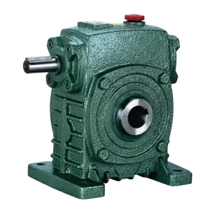
The EP-WPKS is a hollow-bore shaft-mount single speed reducer incorporating a shrink disc clamping system rather than a conventional keyed bore. The shrink disc arrangement creates a pure friction grip on the driven shaft — eliminating the keyway stress concentration that is a common fatigue initiation point on keyed hollow bore reducers subject to the cyclic torsional loading of a scraper bridge drive starting and stopping repeatedly over years of operation. For aerator drives where the shaft transmits bidirectional torque surges from impeller imbalance or entrained debris, the shrink disc also provides overload slip protection: at sufficient overload, the disc releases before the gearbox reaches its structural limit, preventing catastrophic gear or shaft failure.
The shaft load rating of 4 to 365 kg accommodates the structural weight of aerator float assemblies and the moment loads from rake arm structures on clarifier bridges of small to medium diameter. The reduction ratio range of 10:1 to 60:1 within the single stage covers the fan speeds and scraper speeds encountered across municipal and industrial wastewater treatment plant practice.
| Parameter | Spesifikasi |
|---|---|
| Shaft Load Rating | 4 – 365 kg |
| Output Configuration | Hollow bore with shrink disc, shaft-mount |
| Reduction Ratios Available | 10:1 / 15:1 / 20:1 / 25:1 / 30:1 / 40:1 / 50:1 / 60:1 |
| Bahan Perumahan | Grey cast iron (epoxy coating for corrosive environments) |
| Worm Wheel Material | Phosphor bronze / tin bronze |
| Worm Shaft Material | Case-hardened alloy steel, ground tooth flanks (45–55 HRC) |
| Clamping System | Shrink disc (keyless, torque-controlled friction grip) |
| Frame Center Distances | 40 – 250 mm (standard series) |
| Gear Step | Single stage (single reduction) |
| Primary Application | Sludge scraper bridge drive, surface aerator, submerged aerator |
Single Speed Reducer in Sludge Scraper Bridge Drives
Primary and secondary clarifiers in municipal wastewater treatment plants use rotating sludge scraper bridges to move settled solids to the central collection sump for withdrawal. The scraper bridge rotates continuously — typically completing one revolution every 15 to 45 minutes, which corresponds to output shaft speeds of 0.02 to 0.07 RPM for large basins and up to 2–5 RPM for smaller package plant clarifiers. Achieving these very low output speeds from a standard 4-pole motor running at 1450 RPM requires reduction ratios of 300:1 or more when a single gear stage is combined with a secondary chain or belt reduction. In smaller plants, a single stage right-angle worm-gear speed reducer at 60:1 combined with a secondary chain reduction of 5:1 to 10:1 provides the necessary total reduction without the complexity of a multi-stage gear unit.
The torque profile of a scraper drive is unusual among industrial applications: the required torque is low during normal rotation but can spike dramatically when the rake encounters dense sludge accumulation, debris, or — in cold climates — partially frozen sludge layers. The single speed reducer must be selected to handle not just the continuous running torque but the overload peaks that occur without warning. For this reason, a service factor of 1.5 to 2.0 is appropriate for scraper drive specifications, particularly in regions with seasonal temperature variation such as northern European municipal plants or Canadian treatment facilities where winter operating conditions materially alter sludge viscosity and rake resistance.
The EP-WPKS shrink disc configuration offers a practical advantage for scraper bridge drives over keyed hollow bore designs: the shrink disc can be set to release at a calibrated overload torque, acting as a mechanical slip clutch that protects the reducer and bridge structure during severe blockage events. This slip-on-overload behaviour must be verified against the bridge manufacturer’s structural load limits to confirm that the release torque is below the critical threshold for structural damage to the bridge arm or rake assembly.

Aerator Drive Applications: Surface and Submerged Aerator Systems
Aeration is one of the most energy-intensive processes in biological wastewater treatment, and the drive system for surface aerators and slow-speed submerged aerators directly affects both oxygen transfer efficiency and energy consumption. Surface aerators — brush rotors, paddle wheel aerators, and low-speed vertical shaft splash aerators — typically operate at 10 to 100 RPM and are driven through a single stage worm gear speed reducer positioned between the motor and the aerator shaft. The worm speed reducer reduces the motor speed to the aerator’s operating range while providing the torque multiplication needed to overcome the drag resistance of the mixed liquor, which increases significantly when the aeration tank concentration rises during heavy organic loading events.
Submerged slow-speed aerators — disc aerators and cage rotors used in oxidation ditches — operate at similarly low speeds, often 1 to 15 RPM, and are driven by motors through single speed gear reducers mounted on the channel wall structure or on floating pontoon frames. The reducer’s external surface in this installation type may be permanently exposed to the spray zone of the aerator, making the housing surface protection specification critical. Plants in tropical climates — common across Southeast Asia, sub-Saharan Africa, and Central America — combine high ambient temperature with high humidity and biologically active atmospheric conditions that accelerate corrosion of inadequately protected cast iron surfaces. Epoxy-coated housings with stainless steel external fasteners address this exposure without requiring exotic housing materials.
For aerator drives using variable frequency drives (VFDs) to modulate aeration intensity, the thermal behaviour of the single speed reducer at reduced speed requires attention. At operating speeds below approximately 30% of rated input speed, the oil splash within the sump becomes less effective at lubricating the worm-wheel contact and the adjacent shaft bearings. For continuous low-speed operation under VFD control, specifying a synthetic gear oil — rather than mineral oil — provides a more reliable lubricant film at reduced speeds, extending the service life of the bronze worm wheel under low-speed boundary lubrication conditions. A transmission single speed reducer selected with this in mind will maintain consistent performance across the full speed range that VFD control enables.
WP Series Single Speed Reducer Variants: Wastewater Treatment Application Fit
The table below maps four WP-series configurations against the principal drive requirements of sludge scraper and aerator applications to support specification decisions.
| Seri | Output Type | Load Rating | Ratios | Wastewater Application Fit |
|---|---|---|---|---|
| EP-WPKS | Hollow bore + shrink disc | 4 – 365 kg | 10:1 – 60:1 | Scraper bridge drive, oxidation ditch aerator, overload slip protection |
| EP-WPKA | Hollow bore, keyed | 5 – 260 kg | 10:1 – 60:1 | Small clarifier scraper, paddle wheel aerator, package plant drive |
| EP-WPDKA | Hollow bore + motor flange | 5 – 350 kg | 10:1 – 60:1 | Compact motor-reducer unit for surface aerator pontoon frame |
| EP-WPDS | Solid shaft + motor flange (top) | 0.12 – 15 kW input | 10:1 – 60:1 | Secondary drive stage input, ancillary dosing and screen drives |
Lubrication and Planned Maintenance for Wastewater Service Reducers
The gear lubricant in a worm speed reducer used for scraper or aerator duty must remain serviceable across the extremes of wastewater plant operating conditions. Municipal plants in temperate European or North American climates see sump temperatures ranging from near 5°C in winter to 50°C or above in summer — a 45-degree span that challenges a single mineral oil viscosity grade. ISO VG220 mineral gear oil, bronze-compatible and anti-wear additive chemistry, covers this range in most temperate climates. For tropical plants operating year-round at ambient temperatures above 30°C, ISO VG320 provides better film thickness retention at elevated sump temperatures. Synthetic polyalphaolefin gear oil at either ISO VG grade is the preferred choice for facilities in extreme climates or where extended oil change intervals are operationally important.
The initial oil change at 200–500 operating hours removes run-in wear particles from the new worm wheel and shaft surfaces. For scraper drives running continuously at very low output speeds, 500 hours corresponds to several weeks of plant operation, making the initial service interval easy to schedule within a routine plant inspection round. After the break-in change, the oil change interval for mineral oil is 2,000–4,000 hours, or annually — whichever is shorter. Aerator drives that run continuously at moderate speeds with higher thermal loads should trend toward the shorter 2,000-hour interval.
Oil contamination by water is a persistent risk in wastewater treatment environments. Shaft seals on aerator drives exposed to spray and splash require inspection at each oil change. The appearance of milky or discoloured oil is the primary indicator of water ingress; at the first sign, the oil should be changed, the seal inspected, and the seal replaced if any wear or cracking is apparent. Carrying a set of replacement lip seals for the installed reducer models as a site spare reduces the time between identifying a seal issue and completing the repair, minimising the period during which a contaminated oil charge continues to run.

Selection Guide for Sludge Scraper and Aerator Drive Applications
The following four steps provide a structured approach to selecting the appropriate single speed reducer for a new installation or drive replacement in wastewater treatment service.
Step 1 — Define Output Speed and Torque
Confirm the required output shaft speed in RPM from the process design documentation or existing equipment data. For scraper drives, this is typically stated as revolutions per minute at the bridge drive or as peripheral velocity of the rake tip. Calculate or confirm the running torque at the output shaft, then apply a service factor of 1.5–2.0 for scraper duty or 1.25–1.5 for aerator duty.
Step 2 — Calculate Reduction Ratio
Divide the motor synchronous speed by the required output shaft speed to identify the total reduction needed. If the result exceeds 60:1, a secondary reduction stage — chain, belt, or additional gear step — is required alongside the worm reducer at 60:1. Standard ratios of 10:1 through 60:1 are available as catalogue items without lead time for custom gear sets.
Step 3 — Environment and Protection
Specify the external surface protection based on the ambient chemical exposure: standard enamel for indoor or low-humidity installations; epoxy system for open-air clarifiers, spray-zone aerator mounts, or tropical climates. Confirm the shaft seal type and specify stainless steel fasteners for installations with persistent moisture exposure.
Step 4 — Mounting Configuration
Select EP-WPKS for scraper bridge or pontoon aerator drives where overload slip protection and keyless mounting are priorities. Select EP-WPKA for smaller package plants or secondary aerator positions. Select EP-WPDKA where a compact motor-integrated unit is required for a confined pontoon frame. Confirm the output shaft bore diameter, keyway, and shrink disc sizing against the driven shaft dimensions before finalising the order.
For plants evaluating multiple clarifier or aeration lane replacements, standardising on one or two frame sizes across all cells reduces spare-parts inventory and simplifies technician training. The single speed reducer catalogue provides the full range of frame sizes, ratios, and configurations available for selection against your plant survey data.
Komponen Sistem yang Kompatibel
Scraper and aerator drive packages require matched motor and gearhead components for reliable long-term performance. Both of the following product lines are available from the same supply source, enabling unified procurement that simplifies documentation, interchangeability management, and after-sales service at wastewater treatment facilities.

Three-phase motors in IEC and NEMA frames rated for continuous duty with IP55 or IP65 enclosure protection suitable for the wet and humid clarifier environment. Sourcing motor and single speed reducer together ensures that the motor shaft and flange dimensions are compatible with the WPDS and WPDKA motor-flange interface without custom adapter components, reducing installation complexity on scraper bridge and aerator float structures where access for mechanical modifications is limited.

Gearbox Cacing Jangkauan Penuh
Where large clarifier basin diameters require total reduction ratios beyond 60:1 that a single stage cannot achieve — or where output torques exceed the WP single-stage range — the extended worm gearbox programme includes two-stage compound units and NMRV compact series gearboxes. All share the same bronze wheel and hardened steel worm material standards as the WP single speed series, enabling uniform maintenance procedures and lubricant specifications across all drive sizes in the same treatment plant.
Tentang Produsen
The production facility behind these products operates under ISO 9001:2015 certification and maintains a comprehensive manufacturing programme covering worm gear reducers, planetary gear drives, agricultural gearboxes, power take-off shafts, hydraulic cylinders, electric motors, gears, and drive chains. Engineering and fabrication capabilities span ductile iron, cast iron, cast steel, precision cast steel, and cast aluminum housings and assemblies, with in-house production of gears, sprockets, worm gears, pulleys, worms, and shafts in both standard catalogue configurations and application-specific non-standard designs. OEM programmes for wastewater equipment builders, clarifier manufacturers, and aerator system integrators are supported through direct technical collaboration from the engineering team.
Bengkel



Pertanyaan yang Sering Diajukan
Editor: PXY