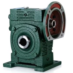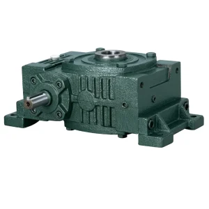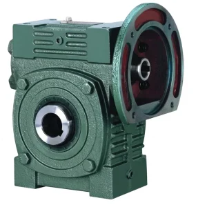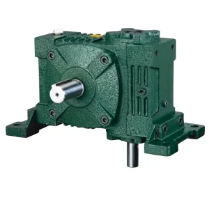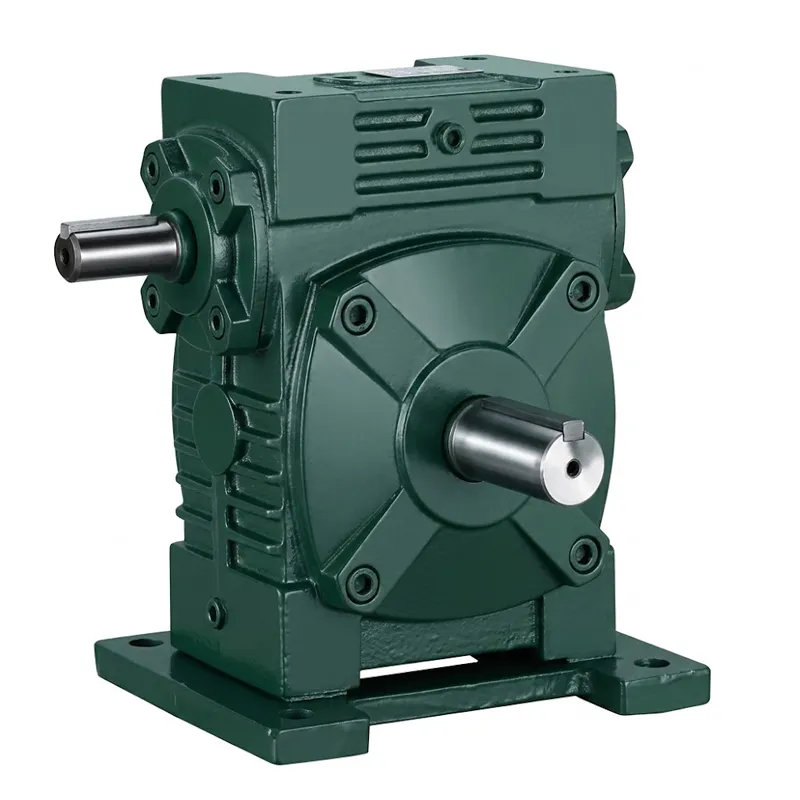
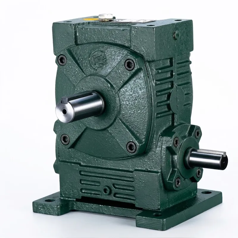
Pengurang Kecepatan Universal EP-WPWA-S
EP-WPWA-S adalah perangkat yang ringkas dan tahan lama. peredam kecepatan universal Dibangun di atas arsitektur roda gigi cacing WPW yang sudah mapan. Tersedia dalam dua konfigurasi rumah utama — WPWA (input horizontal, dudukan dasar padat) dan WPWS (varian input flensa) — seri ini mencakup ukuran rangka dari 40 hingga 250, rentang torsi keluaran hingga kelas beban 350 kg, dan rasio reduksi dari 1/5 hingga 1/60. Hasilnya adalah satu keluarga produk yang menangani sebagian besar kebutuhan penggerak kecepatan rendah dan torsi tinggi di industri dan pertanian tanpa memerlukan rekayasa khusus untuk setiap aplikasi.
Ciri mekanis utama dari reduktor kecepatan roda gigi cacing di kelas ini adalah sudut poros 90 derajat antara input dan output. Geometri ini memungkinkan EP-WPWA-S untuk masuk ke dalam tata letak penggerak di mana reduktor sebaris atau paralel tidak praktis — antara motor dan penggerak konveyor pada sudut siku-siku, atau sebagai titik balik dalam jalur pengemasan multi-sumbu. Rasio reduksi roda gigi cacing juga memberikan resistensi penggerak balik yang melekat, yang dalam banyak aplikasi menghilangkan kebutuhan akan mekanisme rem terpisah dan mengurangi jumlah komponen serta biaya perawatan.
Fleksibilitas arah poros merupakan salah satu keunggulan praktis utama dari seri WPW. Lima konfigurasi arah poros standar — berlabel A hingga E — mencakup kombinasi input kiri/output kanan, input atas, output ganda, dan susunan poros yang diperpanjang. Ini berarti housing yang sama dapat digunakan untuk berbagai orientasi instalasi di berbagai tata letak pabrik, mengurangi jumlah nomor suku cadang unik yang perlu disimpan oleh tim teknik atau pemeliharaan. EP-WPWA-S dipasok sebagai unit mandiri. reduktor roda gigi cacing unit atau dikombinasikan dengan motor listrik yang sesuai sebagai paket penggerak reduktor cacing bermotor, tergantung pada persyaratan integrasi sistem pelanggan.
Pengurang Kecepatan Universal EP-WPWA-S
Reducer Kecepatan Roda Gigi Cacing Seri WPW — Ukuran 40–250 | Rasio 1/5–1/60 | Kapasitas Beban Hingga 350 kg
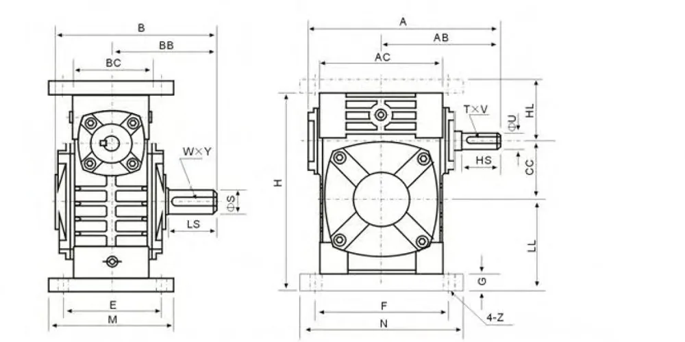
Spesifikasi Teknis EP-WPWA-S — Data Dimensi
| Ukuran | Perbandingan | A | AB | B | BB | AC | BC | CC | HL | II | H | M | N | E | F | G | Z | SMA | U | T×V | Berat (kg) |
|---|---|---|---|---|---|---|---|---|---|---|---|---|---|---|---|---|---|---|---|---|---|
| 40 | 1/5 | 143 | 87 | 114 | 74 | 95 | 61 | 40 | 45 | 60 | 135 | 100 | 130 | 80 | 110 | 10 | 10 | 25 | 12 | 4×2,5 | 4.5 |
| 50 | 1/10 | 175 | 108 | 150 | 97 | 111 | 68 | 50 | 50 | 80 | 165 | 120 | 140 | 95 | 110 | 12 | 12 | 30 | 12 | 5×3 | 7.5 |
| 60 | 1/15 | 198 | 120 | 168 | 112 | 127 | 76 | 60 | 60 | 93 | 195 | 130 | 150 | 105 | 120 | 18 | 12 | 40 | 15 | 5×3 | 11.5 |
| 70 | 1/20 | 231 | 140 | 194 | 131 | 152 | 86 | 70 | 73 | 108 | 233 | 150 | 190 | 115 | 150 | 18 | 15 | 40 | 18 | 5×3 | 15.5 |
| 80 | 1/25 | 261 | 160 | 214 | 142 | 169 | 102 | 80 | 83 | 123 | 268 | 170 | 220 | 135 | 180 | 18 | 15 | 50 | 22 | 7×4 | 24 |
| 100 | 1/30 | 322 | 190 | 254 | 169 | 216 | 117 | 100 | 100 | 150 | 330 | 200 | 270 | 155 | 220 | 20 | 15 | 50 | 28 | 10×4,5 | 39 |
| 120 | 1/40 | 371 | 219 | 282 | 190 | 256 | 124 | 120 | 120 | 180 | 305 | 230 | 320 | 180 | 260 | 25 | 18 | 65 | 30 | 7×4 | 57 |
| 135 | 1/50 | 422 | 249 | 317 | 210 | 296 | 147 | 135 | 135 | 215 | 455 | 250 | 350 | 200 | 290 | 30 | 18 | 75 | 35 | 10×4,5 | 85 |
| 155 | 1/60 | 497 | 295 | 382 | 252 | 345 | 185 | 155 | 155 | 235 | 493 | 280 | 380 | 220 | 320 | 32 | 20 | 85 | 40 | 18×7 | 110 |
| 175 | 1/60 | 534 | 314 | 373 | 255 | 374 | 192 | 175 | 160 | 260 | 558 | 310 | 410 | 250 | 350 | 37 | 21 | 85 | 45 | 14×5,5 | 152 |
| 200 | 1/60 | 580 | 342 | 426 | 319 | 412 | 230 | 200 | 175 | 290 | 620 | 355 | 445 | 290 | 390 | 45 | 24 | 95 | 50 | 20×7,5 | 216 |
| 250 | 1/60 | 705 | 420 | 552 | 385 | 500 | 285 | 250 | 200 | 350 | 750 | 460 | 560 | 380 | 480 | 50 | 28 | 110 | 60 | 25×9 | 350 |
Lima Keunggulan Utama Reducer Cacing Kecepatan Universal EP-WPWA-S
① Rentang Ukuran Bingkai yang Luas
Sebelas ukuran rangka dari 40 hingga 250 memungkinkan para insinyur untuk mencocokkan ukuran fisik dan torsi keluaran secara tepat dengan mesin yang digerakkan — tanpa spesifikasi berlebihan yang meningkatkan biaya dan berat. Unit ukuran 40 memiliki berat 4,5 kg; ukuran 250 memiliki berat 350 kg. Rentang ukuran tersebut mencakup semuanya, mulai dari penggerak konveyor kecil di pabrik pengolahan makanan hingga pengaduk tugas berat di dalam bejana reaktor kimia.
② Konfigurasi Arah Poros Fleksibel
Lima pilihan arah poros (A–E) terintegrasi dalam satu keluarga housing yang sama. Baik instalasi memerlukan tata letak standar kiri-masuk/kanan-keluar, pengaturan input atas, atau ekstensi output ganda, peredam kecepatan universal EP-WPWA-S dapat mengakomodasinya tanpa memerlukan peralatan khusus. Ini merupakan keuntungan signifikan bagi OEM yang merancang mesin untuk diekspor ke berbagai pasar di mana kendala ruang instalasi bervariasi.
③ Pemilihan Rasio Pengurangan Luas
Enam rasio reduksi standar — 1/5, 1/10, 1/15, 1/20, 1/25, 1/30, 1/40, 1/50, 1/60 — memungkinkan penyetelan kecepatan keluaran yang presisi tanpa tahapan roda gigi perantara. Dalam aplikasi di mana rasio reduksi roda gigi cacing 1/60 dipilih, kecenderungan penguncian otomatis yang melekat pada geometri ulir cacing juga memberikan resistensi penggerak balik yang fungsional, menghilangkan kebutuhan akan rem penahan terpisah dalam banyak aplikasi konveyor beban vertikal atau yang dibantu gravitasi.
④ Casing Besi Cor untuk Kekakuan dan Pembuangan Panas
Rumah besi cor berusuk ini melakukan dua fungsi sekaligus: memberikan kekakuan struktural di bawah momen lentur yang ditimbulkan oleh beban poros yang menjorok, dan geometri sirip eksternal meningkatkan luas permukaan untuk pembuangan panas pasif selama operasi tugas berkelanjutan. Pada suhu lingkungan hingga 40°C — standar di banyak lingkungan industri di Asia Tenggara, Timur Tengah, dan Afrika khatulistiwa — rumah WPW mempertahankan suhu bak penampung yang dapat diterima tanpa pendinginan paksa.
⑤ Pemasangan Flensa Motor Langsung
Varian WPWS dirancang dengan flensa input standar IEC yang menerima pemasangan motor langsung tanpa kopling atau braket perantara. Konfigurasi reduktor cacing bermotor yang ringkas ini mengurangi panjang aksial, menghilangkan persyaratan penyelarasan poros, dan memangkas waktu pemasangan secara signifikan — sebuah keuntungan praktis bagi pembuat mesin di Eropa, Australia, dan Amerika Utara di mana tenaga kerja perakitan merupakan bagian signifikan dari biaya mesin.
Bagaimana Cara Kerja Reducer Gigi Cacing — Prinsip Kerja EP-WPWA-S
Prinsip kerja dari sebuah peredam kecepatan universal Dalam keluarga WPW, semuanya dimulai dengan poros cacing — elemen input. Cacing adalah ulir heliks yang dikerjakan pada poros baja yang dikeraskan, dan ia berpasangan pada sudut 90 derajat dengan roda gigi cacing: roda gigi perunggu atau besi cor dengan bentuk gigi melengkung yang melilit profil ulir cacing. Saat cacing berputar, setiap ulir menggerakkan roda gigi cacing sejauh satu jarak antar gigi per putaran — menciptakan pengurangan kecepatan dan perkalian torsi yang sesuai yang mendefinisikan perilaku penggerak roda gigi cacing.
Rasio reduksi roda gigi cacing ditentukan oleh jumlah gigi roda cacing dibagi dengan jumlah ulir cacing awal. Cacing satu ulir yang berpasangan dengan roda 60 gigi menghasilkan rasio 1/60 — enam puluh putaran motor untuk setiap satu putaran keluaran, dengan peningkatan torsi 60 kali lipat (dikurangi kerugian efisiensi). Peredam kecepatan universal EP-WPWA-S dirancang di seluruh rentang rasionya dengan sudut ulir dan sudut tekanan yang dipilih untuk menyeimbangkan efisiensi mekanis terhadap perilaku penguncian otomatis, karena kedua karakteristik tersebut saling bertentangan seiring peningkatan rasio.
Pada rasio reduksi yang lebih tinggi, sudut ulir menjadi lebih dangkal, gesekan meningkat, dan rangkaian roda gigi mendekati kondisi penguncian otomatis di mana torsi balik dari beban tidak dapat memutar poros input. Hal ini berguna dalam aplikasi pengangkatan atau pengindeksan tetapi menghasilkan efisiensi maju yang lebih rendah. Pada rasio yang lebih rendah — 1/5, 1/10 — efisiensi lebih tinggi dan rangkaian dapat diputar balik. Memahami pertimbangan ini adalah yang membedakan spesifikasi yang tepat. peredam kecepatan cacing dari yang mudah panas berlebih saat beroperasi atau membutuhkan rem penahan yang tidak perlu. Lembar data peredam kecepatan universal EP-WPWA-S menyediakan kurva efisiensi di seluruh rentang rasio karena alasan ini.

Standar Material & Manufaktur
Rumah peredam kecepatan universal EP-WPWA-S dicetak dari besi cor abu-abu sesuai spesifikasi GB/T 9439 HT200 — jenis yang sama yang digunakan pada rangka mesin perkakas tugas berat, dipilih di sini karena sifat peredaman getaran dan kemudahan pengerjaannya yang sangat baik. Setelah dicetak, rumah tersebut menjalani pengeboran presisi pada pusat permesinan dengan toleransi posisi yang dijaga hingga ±0,02 mm pada pusat lubang bantalan, yang memastikan paralelisme poros yang benar dan geometri kontak cacing-ke-roda di seluruh masa pakai rumah terlepas dari orientasi pemasangannya.
Poros ulir cacing dibuat dari baja pengerasan permukaan 20CrMnTi, dikarburisasi dan dikeraskan hingga kedalaman lapisan 0,8–1,2 mm dan kekerasan permukaan 58–62 HRC. Tingkat kekerasan ini, dikombinasikan dengan tegangan sisa tekan dari lapisan karburisasi, memberikan ketahanan tinggi pada sisi ulir cacing terhadap keausan abrasif bahkan dalam kondisi pelumasan batas yang terjadi selama siklus start-stop. Material pelek roda cacing adalah perunggu fosfor (ZCuSn10Pb1) yang dicetak secara sentrifugal ke hub besi cor ulet — perunggu memberikan gesekan rendah dan kesesuaian yang baik dengan sisi ulir cacing yang dikeraskan, sementara hub besi cor ulet menangani transfer beban torsi ke poros keluaran tanpa risiko patah getas.
Bantalan poros input dan output berupa bantalan bola alur dalam pada poros cacing dan bantalan rol tirus pada poros roda gigi cacing untuk ukuran 100 ke atas, di mana kapasitas beban aksial menjadi faktor penentu dalam kondisi poros yang menjorok. Semua bantalan dipasok dengan jarak bebas internal C3 yang sesuai untuk pengoperasian pada suhu tinggi, dan rumah bantalan mencakup segel oli integral yang sesuai untuk oli roda gigi mineral yang digunakan dalam bak penampung reduktor kecepatan universal EP-WPWA-S. Flensa input standar IEC pada varian WPWS dikerjakan dengan toleransi pemasangan yang menerima motor pemasangan langsung tanpa shim.

Skenario Aplikasi — Di mana Peredam Kecepatan Universal EP-WPWA-S Digunakan
Penggerak Konveyor Makanan & Minuman — Eropa & Australia
Jalur konveyor higienis di fasilitas pengolahan makanan di Jerman, Prancis, dan Australia menggunakan peredam kecepatan universal EP-WPWA-S pada rasio 1/20–1/40 untuk menggerakkan konveyor sabuk dan bilah pada kecepatan terkontrol. Rumah berbahan besi cor dapat dibersihkan dengan air tanpa khawatir akan masuknya cairan pada titik penyegelan poros, dan geometri 90 derajat menjaga motor tetap terpisah dari zona produk — sebuah keuntungan tata letak dalam ruang yang sempit di aula pembotolan dan pengemasan.
Sistem Penggerak Mesin Pertanian — AS & Brasil
Penggerak auger biji-bijian, sistem pengukur benih, dan penyebar pupuk di seluruh sektor peralatan pertanian AS dan Brasil bergantung pada mesin kompak. peredam kecepatan cacing Untuk menurunkan kecepatan PTO atau motor listrik ke putaran rendah (RPM) dan torsi tinggi yang dibutuhkan oleh mekanisme pengolahan tanah atau penanganan biji-bijian. Peredam kecepatan universal EP-WPWA-S dengan ukuran 70–120 mencakup rentang torsi yang dibutuhkan untuk sebagian besar aplikasi alat pertanian skala menengah.
Peralatan Penanganan dan Pengangkatan Material — Asia Tenggara
Di fasilitas manufaktur dan pergudangan di seluruh Malaysia, Vietnam, dan Thailand, EP-WPWA-S dengan rasio 1/50–1/60 dan kemampuan penguncian otomatis menggantikan rem mekanis pada penggerak pengangkatan sumbu vertikal dan penggerak pintu gerbang. Hambatan penggerak balik yang melekat pada gearbox penggerak cacing rasio tinggi mempertahankan posisi beban tanpa pengereman bertenaga — mengurangi konsumsi listrik dan menghilangkan perawatan rem pada operasi multi-shift.
Proyek Pembangunan Pabrik Kimia & Pengolahan Air — Timur Tengah & Korea Selatan
Penggerak pengaduk lumpur, aktuator katup, dan penggerak pompa dosis kimia di instalasi pengolahan air dan air limbah di seluruh Korea Selatan dan negara-negara Teluk menggunakan gearbox penggerak cacing tugas berat pada ukuran rangka yang lebih besar. Rentang EP-WPWA-S ukuran 175–250 menangani beban torsi tugas kontinu dari aplikasi pencampuran kecepatan rendah, di mana RPM keluaran rendah dan perkalian torsi tinggi dari rasio 1/60 menghilangkan kebutuhan akan tahap pengurangan kecepatan tambahan.
Produsen Reducer Roda Gigi Cacing
Fasilitas produksi kami telah beroperasi selama lebih dari sepuluh tahun, memproduksi peralatan transmisi daya mekanik di berbagai macam produk: gearbox pertanian, reduktor roda gigi cacing, penggerak roda gigi planet, poros penggerak daya, silinder hidrolik, roda gigi, sproket, dan rakitan khusus. Fasilitas ini memegang sertifikasi ISO 9001:2015, dan kontrol kualitas terintegrasi di seluruh proses — mulai dari inspeksi material yang masuk berupa bahan baku cor hingga pengujian torsi keluaran akhir dan uji celah pada unit gearbox yang sudah jadi.
Kami mendesain dan memproduksi dari besi cor ulet, besi cor, baja cor, baja cor presisi, dan aluminium cor, menghasilkan produk katalog standar dan komponen mekanik non-standar sesuai gambar pelanggan. Infrastruktur permesinan yang sama yang memproduksi rumah roda gigi cacing dengan toleransi lubang ±0,02 mm juga memproduksi roda gigi, sproket, roda gigi cacing, puli, poros cacing, dan komponen penggerak lainnya — semuanya di bawah satu atap. Integrasi vertikal ini berarti konsistensi dimensi di seluruh bagian yang saling berpasangan dan satu titik akuntabilitas teknis untuk seluruh sistem penggerak.
Bengkel




Produk yang Kompatibel — Sistem Penggerak Lengkap dari Satu Sumber
EP-WPWA-S dirancang untuk berinteraksi langsung dengan rangka motor IEC standar dan seluruh rangkaian aksesori penggerak kami — tanpa memerlukan adaptor khusus.
Dengan memasangkan EP-WPWA-S dengan motor listrik yang sesuai, tercipta unit penggerak reduktor cacing bermotor yang siap untuk dipasang langsung. Rangkaian motor listrik kami mencakup motor satu fasa dan tiga fasa berbingkai IEC dari 0,18 kW hingga 22 kW — dirancang untuk memberikan kecepatan dan daya input terukur untuk setiap ukuran bingkai WPW dan rasio reduksi.

Di luar seri WPW, rangkaian gearbox cacing lengkap kami mencakup tipe housing NMRV, RV, WD, dan CW — meliputi rasio reduksi dari 1:5 hingga 1:100 baik dalam housing aluminium kompak maupun housing besi cor tugas berat. Untuk aplikasi di mana rasio operasi atau konfigurasi pemasangan EP-WPWA-S tidak sesuai, tim teknis kami dapat mengidentifikasi alternatif dari katalog gearbox reduktor cacing yang lebih luas tanpa perlu mengganti pemasok.

Pertanyaan yang Sering Diajukan
Q1. Bagaimana cara kerja reduktor roda gigi cacing, dan apa yang membuat EP-WPWA-S cocok untuk penggerak industri tugas kontinu di Asia Tenggara?
Reducer roda gigi cacing mengubah putaran motor berkecepatan tinggi dan torsi rendah menjadi output berkecepatan rendah dan torsi tinggi melalui persambungan poros cacing yang dikeraskan terhadap roda gigi cacing perunggu pada sudut 90 derajat. Setiap putaran cacing memajukan roda gigi sejauh satu jarak antar gigi — menghasilkan pengurangan kecepatan dan perkalian torsi yang mendefinisikan penggerak tersebut. Reducer kecepatan universal EP-WPWA-S cocok untuk aplikasi tugas kontinu di lingkungan industri yang hangat seperti di Malaysia, Vietnam, dan Thailand karena rumah besi cor berusuk secara pasif menghilangkan panas selama pengoperasian yang lama, material roda gigi perunggu fosfor mempertahankan kemampuan adaptasi yang baik di bawah beban berkelanjutan, dan bantalan rol tirus yang digunakan pada ukuran rangka yang lebih besar menangani beban aksial berkelanjutan dari penggerak konveyor dan pengaduk tanpa memerlukan penyesuaian yang sering.
Q2. Apa tujuan dari peredam kecepatan universal dalam sistem penggerak mesin pertanian di pertanian AS atau Brasil?
Pada peralatan pertanian, tujuan peredam kecepatan universal adalah untuk mengubah output kecepatan tinggi dari motor listrik atau poros PTO menjadi RPM yang jauh lebih rendah dan torsi yang lebih tinggi yang dibutuhkan oleh mekanisme pengolahan tanah atau penanganan biji-bijian agar dapat beroperasi dengan benar. Roda pengukur benih yang berputar pada 1500 rpm akan menyebabkan kesalahan pemasukan; sedangkan yang berputar pada 25 rpm — output dari peredam kecepatan penggerak cacing rasio 1/60 — akan menempatkan benih dengan akurat. Peredam kecepatan universal EP-WPWA-S digunakan pada penggerak auger biji-bijian, sistem distribusi pupuk, dan titik transfer konveyor di seluruh wilayah pertanian Midwest AS dan cerrado Brasil karena geometri 90 derajatnya yang ringkas sesuai dengan rangka implement yang sempit pada peralatan yang dipasang pada traktor dan yang ditarik.
Q3. Rasio reduksi roda gigi cacing mana yang sebaiknya dipilih oleh seorang insinyur pabrik pengolahan makanan Eropa untuk konveyor sabuk yang beroperasi dengan kecepatan 15 meter per menit?
Rasio yang tepat bergantung pada kecepatan motor input dan diameter sproket atau puli penggerak pada poros output — insinyur menghitung RPM output yang dibutuhkan terlebih dahulu, kemudian membagi kecepatan input dengan angka tersebut untuk menemukan rasionya. Untuk motor 1400 rpm yang menggerakkan puli berdiameter 200 mm pada kecepatan 15 m/menit, RPM output yang dibutuhkan kira-kira 24 rpm, memberikan rasio target sekitar 1/58 — pilihan standar terdekat dalam rangkaian peredam kecepatan universal EP-WPWA-S adalah 1/60.
Q4. Di mana seorang insinyur pabrik Australia dapat menemukan pengganti peredam kecepatan universal yang sesuai dengan dimensi poros seri WPW dan pola baut pemasangannya?
Seri WPW adalah keluarga housing standar yang diproduksi dengan spesifikasi dimensi yang konsisten di berbagai produsen — jarak pusat, diameter poros, dimensi alur pasak, dan pola baut didefinisikan dalam standar dan tidak bervariasi menurut merek. Sebagai contoh, reduktor kecepatan universal pengganti dalam ukuran WPW 100 akan memiliki dimensi A sebesar 322 mm, diameter poros keluaran 50 mm, dan alur pasak T×V sebesar 10×4,5 mm terlepas dari pabrik mana yang memproduksi unit aslinya. Bagi para insinyur pabrik di Australia yang mencari pengganti langsung, mengkonfirmasi nomor ukuran dan rasio dari pelat nama unit yang ada sudah cukup untuk menentukan reduktor kecepatan universal EP-WPWA-S yang kompatibel tanpa memerlukan pengukuran setiap dimensi di lokasi.
Q5. Apakah roda gigi cacing mengurangi kecepatan secara efektif untuk aplikasi pencampuran dan pengadukan kecepatan rendah di pabrik kimia Korea Selatan?
Ya — roda gigi cacing termasuk di antara mekanisme pengurangan kecepatan satu tahap yang paling efektif untuk mencapai RPM keluaran yang sangat rendah dari input motor kecepatan standar. Pada rasio 1/60, motor 1400 rpm menghasilkan sekitar 23 rpm pada poros keluaran dalam satu tahap pengurangan, tanpa roda gigi perantara. Untuk penggerak pencampuran dan pengadukan pabrik kimia di Korea Selatan — di mana proses pengentalan lumpur dan pemberian dosis bahan kimia membutuhkan torsi kecepatan rendah yang berkelanjutan — peredam kecepatan universal EP-WPWA-S pada ukuran 175 atau 200 memberikan kombinasi kecepatan keluaran rendah, perkalian torsi tinggi, dan resistensi pengereman sendiri yang menjadikannya pilihan praktis yang lebih disukai daripada peredam poros paralel yang membutuhkan dua tahap pengurangan untuk mencapai kecepatan keluaran yang setara.
Q6. Kapan pemasangan reduktor roda gigi cacing paling baik dilakukan, dan prosedur pengisian oli apa yang harus diikuti oleh tim perawatan di Timur Tengah untuk kondisi lingkungan yang panas?
Pemasangan reduktor roda gigi cacing sebaiknya diselesaikan sebelum mesin penggerak dirakit di sekitarnya — sehingga memberikan akses ke baut pemasangan dan kopling poros dari semua sisi tanpa halangan. Dalam kondisi lingkungan panas yang khas di pabrik-pabrik industri negara-negara Teluk (40–50°C), bak reduktor kecepatan universal EP-WPWA-S harus diisi dengan oli roda gigi mineral ISO VG 220 atau VG 320, bukan rekomendasi standar VG 150, karena viskositas yang lebih tinggi mengimbangi penurunan viskositas yang terjadi pada suhu bak yang tinggi.
Tentukan Reducer Kecepatan Universal EP-WPWA-S Anda
Sebutkan kecepatan input Anda, torsi output yang dibutuhkan, rasio, dan arah poros — kami akan memastikan ukuran dan konfigurasi yang tepat untuk aplikasi Anda.
Editor: PXY