

Super Gear
Precision parallel-shaft spur gears for automotive, industrial, agricultural, and precision instrument applications — ISO 9001:2015 & TS16949 certified, OEM/ODM supported.
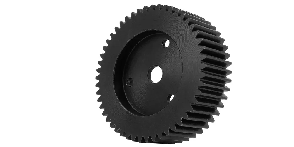

Module M0.15 – M8
OD Φ3 mm – Φ600 mm
AGMA / DIN / ISO / JIS
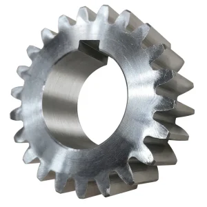
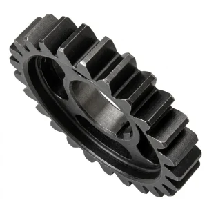
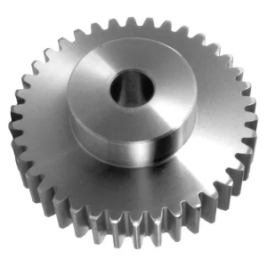
What Is a Spur Gear?
Structure & Working Principle
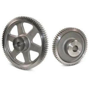
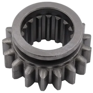
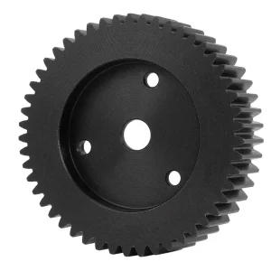
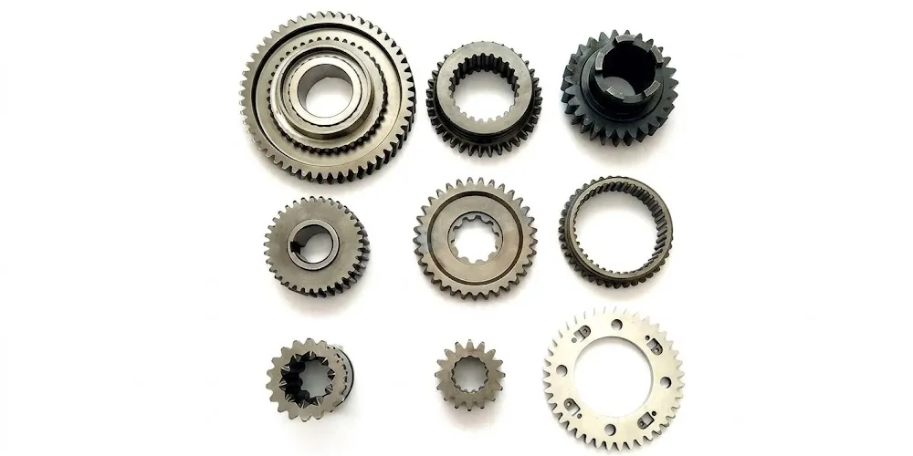
A spur gear is a cylindrical gear with straight teeth cut parallel to the rotation axis. When two spur gears mesh, their involute tooth profiles maintain a constant velocity ratio throughout engagement — known as conjugate action — ensuring smooth, predictable power transmission without speed fluctuations.
Unlike helical gears, spur gears generate only radial loads on shaft bearings, eliminating axial thrust forces. This simplifies bearing selection, reduces housing complexity, and lowers system cost — advantages that make spur gears the default choice for compact, moderate-speed parallel-shaft drives from micro-instruments to heavy industrial equipment.
Key Technical Parameters
- Module (m) — tooth size; must match between meshing gears
- Sudut Tekanan — standard 20°; affects tooth strength and smoothness
- Number of Teeth (z) — determines gear ratio with paired gear
- Pitch Diameter — m × z; the reference circle for meshing
- Face Width — wider = more torque capacity, less misalignment tolerance
- Accuracy Grade — DIN / ISO / AGMA grade governs noise and life
- Material & Heat Treatment — sets surface hardness and core toughness
Carbon Steel (C45 / S45C)
Cost-effective general-purpose grade. Induction hardened to HRC 45–55. Ideal for medium-load industrial gearboxes and conveyor drives.
Stainless Steel (304 / 316)
Corrosion-resistant for wet, chemical, or marine environments. Also chosen for applications where rust contamination is a hygiene concern. Moderate strength.
Aluminum Alloy
Lightweight — reduces inertia in high-speed, low-torque drives. Common in motorsport, robotics, and aerospace sub-systems where mass is a critical specification parameter.
Cast Iron (HT250 / QT450)
Vibration damping, good machinability, cost-effective for large low-speed gears. Suitable for industrial gearboxes operating in dirty, abrasive environments.
Spur Gear Material Selection Guide
Alloy Steel (42CrMo / 20CrMnTi)
Highest strength and fatigue life. Case-hardened to HRC 58–62. Best for structural drives with shock loads: tractors, mining, construction equipment.
POM (Acetal / Delrin)
Self-lubricating, low noise, corrosion-free. Friction coefficient 0.10–0.15 against steel. Best for automotive actuators, instrument drives, and food-contact applications.
Brass (CuZn)
Non-magnetic, non-sparking, EMI-neutral. Selected for sensor-adjacent positions in automotive electronics and precision instruments. Good machinability for micro-module gears.
Bronze
Excellent emergency running properties and low friction against steel shafts. Preferred where occasional loss of lubrication is possible without immediate catastrophic failure.

Standards Compliance

Get a Free Spur Gear Quote
Tell us your module, ratio, material, and application — we’ll respond with specifications, pricing, and lead time within 24 hours.

How to Select the Right Spur Gear

Define Module & Pitch
Module is the fundamental size parameter — both gears in a meshing pair must share the same module and pressure angle. Calculate required module from torque, shaft spacing, and desired tooth count. Standard modules: 0.5, 0.8, 1, 1.5, 2, 2.5, 3, 4, 5, 6, 8, 10.
Determine Gear Ratio
Gear ratio = driven teeth ÷ driving teeth. Spur gear single-stage ratios typically range from 1:1 to 1:7. For higher ratios, use two stages or combine with a worm reducer upstream. Avoid ratios below 1:1.2 or above 1:8 in a single mesh for best efficiency.
Select Material Grade
Match material to load and environment: alloy steel (42CrMo) for high-torque structural drives; POM for quiet, lubrication-free precision drives; stainless for wet or corrosive environments; brass for EMI-sensitive positions. Harder surface = longer life but higher cost and longer lead time.
Specify Accuracy Grade
Higher accuracy grade = lower noise, better load distribution, longer life — but higher cost. Match grade to application: DIN 8–10 for general machinery; DIN 6–7 for moderate precision conveyors and gearboxes; DIN 4–6 (ISO 4–5) for instrumentation, robots, and automotive NVH requirements.
Check Bore & Hub Geometry
Specify bore diameter, keyway dimensions (width × depth per DIN 6885 or ANSI B17.1), and set-screw positions before ordering. OEM bore configurations including spline bores, D-flat bores, and press-fit hubs are all available within our ODM programme.
Calculate Face Width & Safety Factor
Face width is typically 8–12× module for standard drives. Apply a service factor (AGMA KA / DIN KAp) of 1.25–2.5 depending on shock load class before finalising face width. For tractor and mining applications, minimum safety factor of 1.5 on tooth root bending stress is recommended.