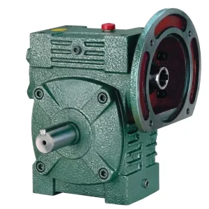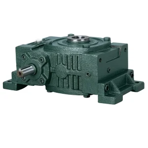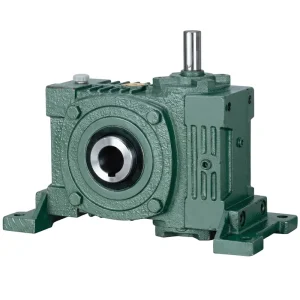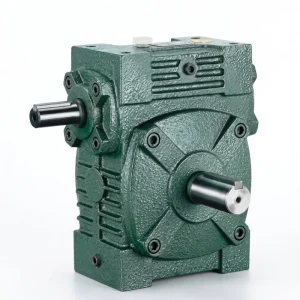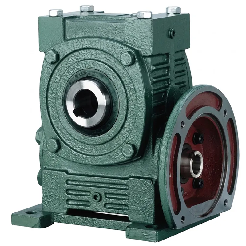
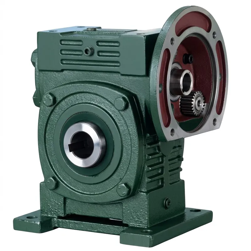
EP-WPWDKA-S 0.12 to 15 kW Universal Speed Reducer
The EP-WPWDKA-S series comprises universal worm gear reducers available in WPWDKA and WPWDKS configurations, engineered for direct motor integration. Covering sizes 40 to 250, these units support power inputs from 0.12 kW to 15.0 kW with reduction ratios ranging from 1/5 to 1/60. Weighing between 5 kg and 395 kg, they feature robust cast iron housings and versatile shaft direction options (A-B) to accommodate complex layouts. Key specifications include motor flange compatibility up to M16 and output shafts up to 28×116.4 mm. This series ensures reliable torque transmission and compact design, making it ideal for industrial machinery requiring precise speed control and efficient direct-drive capabilities in space-constrained environments.
EP-WPWDKA-S Universal Speed Reducer — 0.12 to 15 kW Series
The EP-WPWDKA-S universal speed reducer combines a motor-mounting flange with a dual hollow-bore output in a single, compact worm gear gearbox housing. Designed for engineers who need a pre-integrated drive module without the complexity of a separate coupling stage, this universal speed reducer accepts an IEC-frame motor on one face and delivers high-torque, low-speed output through hollow bores on both sides — making symmetrical or single-side machine drive arrangements equally straightforward to implement. Input power coverage spans 0.12 kW through 15 kW, with frame sizes 40 through 250 and reduction ratios from 1/5 to 1/60.
Whether you are specifying a new universal speed worm reducer for a processing line in Canada, finding a replacement universal speed reducer for an existing agitator shaft in the Netherlands, or sourcing a large universal speed reducer for a heavy conveyor installation in Australia, the WPWDKA-S series delivers the dimensional consistency and build quality your operation requires. Every unit is pre-filled with gear oil and run-tested before leaving the production facility, so installation begins the moment the package arrives on your workshop floor.
Technical Specifications — WPWDKA-S Series Universal Speed Reducer
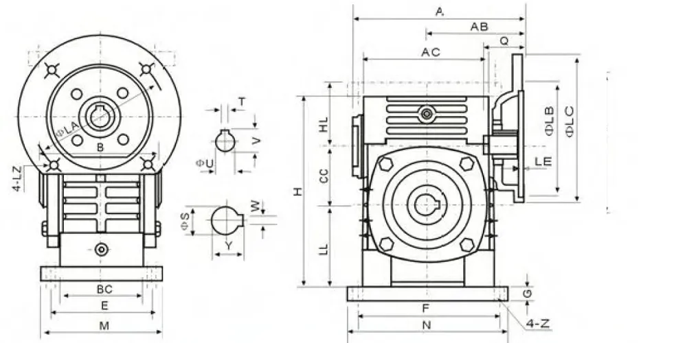
The table below provides complete dimensional and rating data for the WPWDKA-S series from frame size 40 to 250. All linear dimensions are in millimetres (mm); unit weight in kilograms (kg). Input power values reflect rating at the stated reduction ratio at 1400 rpm, service factor 1.0. For applications with shock loading, intermittent reversing, or duty cycles exceeding 10 hours/day, apply the appropriate service factor and select the next larger frame size. Output shaft dimensions are expressed as W×Y (output shaft diameter mm × keyway width mm). Input hole is expressed as T×V (diameter mm × depth mm). Motor flange dimensions LA, LB, LC, LE, LZ indicate the IEC flange register and bolt pattern.
| Size | Input (kW) | الف | AB | B | AC | BC | CC | HL | LL | H | M | N | E | F | G | Z | Flange LZ/Bolt | Input T×V | S | Output W×Y | Weight (kg) |
|---|---|---|---|---|---|---|---|---|---|---|---|---|---|---|---|---|---|---|---|---|---|
| 40 | 0.12 | 135 | 75 | 85 | 95 | 61 | 40 | 45 | 60 | 135 | 130 | 130 | 80 | 110 | 10 | 10 | 4 / M8 | 4×12.8 | 16 | 6×18.8 | 5 |
| 50 | 0.18 | 151 | 83 | 105 | 111 | 68 | 50 | 50 | 80 | 165 | 120 | 140 | 95 | 110 | 15 | 12 | 4 / M8 | 4×12.8 | 20 | 6×22.8 | 8 |
| 60 | 0.37 | 167 | 91 | 110 | 127 | 76 | 60 | 60 | 93 | 195 | 130 | 150 | 105 | 120 | 18 | 12 | 4 / M8 | 5×16.3 | 25 | 8×28.3 | 12.5 |
| 70 | 0.37 / 0.75 | 200 / 202 | 109 / 111 | 130 | 152 | 86 | 70 | 73 | 108 | 233 | 150 | 190 | 115 | 150 | 18 | 15 | 4 / M8–M10 | 5×16.3 / 6×21.8 | 30 | 8×33.3 | 17 |
| 80 | 0.75 / 1.5 | 225 | 125 | 150 | 169 | 102 | 80 | 83 | 123 | 268 | 170 | 220 | 135 | 180 | 18 | 15 | 4.5 / M10 | 6×21.8 / 8×27.3 | 35 | 10×38.3 | 26 |
| 100 | 1.5 | 280 | 148 | 160 | 216 | 117 | 100 | 100 | 150 | 330 | 190 | 270 | 155 | 220 | 20 | 15 | 4.5 / M10 | 8×27.3 | 40 | 12×43.3 | 41.5 |
| 120 | 2.2 / 3.0 | 333 | 181 | 175 | 256 | 124 | 120 | 120 | 180 | 395 | 230 | 320 | 180 | 260 | 25 | 18 | 5 / M12 | 8×31.3 | 45 | 14×48.8 | 60 |
| 135 | 3.0 / 4.0 | 375 | 202 | 210 | 296 | 147 | 135 | 135 | 215 | 455 | 250 | 350 | 200 | 290 | 30 | 18 | 5 / M12 | 8×31.3 | 60 | 18×64.4 | 90 |
| 155 | 5.5 | 448 | 247 | 256 | 345 | 185 | 155 | 135 | 235 | 493 | 290 | 380 | 220 | 320 | 32 | 21 | 5 / M12 | 10×41.3 | 70 | 20×74.9 | 118 |
| 175 | 5.5 / 7.5 | 481 | 262 | 282 | 374 | 192 | 175 | 160 | 260 | 558 | 310 | 410 | 250 | 350 | 37 | 21 | 5 / M12 | 10×41.3 | 80 | 22×85.4 | 167 |
| 200 | 11.0 | 543 | 285 | 320 | 412 | 230 | 200 | 175 | 290 | 620 | 355 | 445 | 290 | 390 | 45 | 24 | 6 / M16 | 12×45.3 | 85 | 22×90.4 | 237 |
| 250 | 11.0 / 15.0 | 615 | 330 | 400 | 500 | 285 | 250 | 200 | 350 | 750 | 450 | 560 | 380 | 480 | 50 | 28 | 6 / M16 | 12×45.3 | 110 | 28×116.4 | 395 |
All dimensions in mm. Weight in kg. Ratios 1/5 to 1/60 apply to all sizes. Scroll horizontally on mobile to view all columns.
Five Key Advantages of the EP-WPWDKA-S Universal Speed Reducer
The WPWDKA-S universal speed reducer merges two components that engineers often source separately — a motor mounting flange and a hollow-bore output — into a single precision housing. The motor attaches directly to the input face; the driven shaft passes straight through the output bore. This eliminates both the shaft coupling and the intermediate adapter plate that a bolt-together arrangement would require, reducing the drive package length by up to 80 mm across typical frame sizes and keeping the machine's overall length within target.
Unlike single-bore designs, the WPWDKA-S universal speed reducer configuration exposes both sides of the output bore (shaft direction A or B as standard). A driven shaft can pass completely through the gearbox and be supported on both ends — essential in roller-table and twin-drive conveyor layouts where the shaft must be located on two bearing points. This doubles the support stability under radial load and effectively removes any cantilevered bending moment from the gearbox output, extending bearing life noticeably in heavy-cycle applications.
From a compact 0.12 kW drive on a small indexing conveyor to a 15 kW motor pairing on a large industrial mixer, the EP-WPWDKA-S series universal speed reducer covers the entire practical range of worm-drive applications without requiring a change of product family. For OEM machine builders producing multiple equipment variants at different power levels, standardising on a single worm gear reducer gearbox family reduces the number of distinct part numbers, simplifies spare-parts stocking, and speeds up service support for exported machines worldwide.
Ratios of 1/5, 1/10, 1/15, 1/20, 1/25, 1/30, 1/40, 1/50, and 1/60 are available throughout the WPWDKA-S universal speed reducer range. Each ratio is achieved by selecting the appropriate worm-and-wheel set within the same housing, so the external mounting dimensions remain constant regardless of the chosen worm gear reduction ratio. Procurement teams in South Korea and Brazil who need to maintain a common machine interface across product variants will find this particularly valuable when adapting an existing platform for different output speeds.
Every EP-WPWDKA-S universal speed reducer unit is produced under an ISO 9001:2015 certified quality management system covering incoming material inspection, in-process dimensional checks, tooth contact verification, and a no-load run test before dispatch.
How Does a Worm Gear Reducer Work?
The worm drive speed reducer operates on a straightforward but mechanically elegant principle. A hardened steel worm — essentially a precision helical screw — meshes at 90 degrees with a bronze worm wheel. As the motor rotates the worm, each thread lead advances the wheel by exactly one tooth. Since the wheel carries many more teeth than the worm has starts, the ratio of input revolutions to output revolutions is large — producing the reduction in speed and the corresponding increase in torque that industrial processes require.
Do worm gears reduce speed? Definitively yes — that is the central purpose of the entire worm gear speed reducer family. The reduction ratio is set during manufacture by choosing a worm with a specific number of thread starts and pairing it with a wheel that has the corresponding tooth count. For instance, a single-start worm engaging a 60-tooth wheel produces a 1/60 ratio: at 1400 rpm motor input, the output shaft turns at approximately 23 rpm, delivering roughly 60 times the motor's output torque before efficiency losses. In the EP-WPWDKA-S universal speed reducer design, this output torque emerges at the hollow bore and transfers directly to the inserted driven shaft with no coupling losses.
Materials & Build Quality of Universal Speed Reducer
The EP-WPWDKA-S universal speed reducer housing is cast in HT200 grey cast iron — a material that balances compressive strength, excellent machinability, and natural vibration damping. The casting geometry incorporates integral reinforcing ribs around the bore bore seats and flange faces to prevent flexure under the combined radial and axial loads that arise from the worm mesh reaction forces. Each housing is precision-bored on a CNC horizontal machining centre to achieve the shaft-bore concentricity needed for accurate gear mesh contact and minimal noise generation across all operating speeds.
The worm shaft is manufactured from 20CrMnTi carburizing steel. Following rough machining, the shaft is carburized to achieve a case depth of 0.8–1.2 mm, then quenched and tempered to a surface hardness of HRC 58–62 while retaining a tough, ductile core. This heat-treatment profile creates a tooth surface that resists the abrasive and adhesive wear associated with sustained worm-drive sliding contact, while the softer core absorbs shock loads from motor start-up transients and variable process loads without risk of brittle fracture.
The worm wheel is centrifugally cast or sand-cast in ZCuSn10Pb1 phosphor bronze — a tin-lead bronze alloy long established as the optimum material for steel-driven worm wheels due to its low friction coefficient against hardened steel and its natural conformability under run-in sliding contact. The combination of a hardened steel worm and a bronze wheel keeps operating temperature lower than equivalent ferrous pairings, extending lubricant service intervals and reducing the thermal load on output bore seals.
Application Scenarios of Universal Speed Reducer
The EP-WPWDKA-S universal speed reducer is a practical solution for any application that benefits from a motor-flange and hollow-bore output in a single assembly. By removing the separate coupling stage, this universal speed worm reducer cuts both the installation time and the number of alignment-sensitive interfaces in the drive train. The sectors below represent the principal industries — from processing plants in Brazil and Colombia to automation lines in South Korea and the UK — where this configuration consistently earns its place over alternative drive architectures.
Roller Table & Conveyor Drives
Powered roller tables in logistics centres and automotive assembly plants are among the most common applications for this worm gear reducer gearbox configuration. The driven roller shaft passes fully through the dual hollow bore, with the gearbox body clamped to the frame rail. Both bore ends support the roller shaft, distributing the radial load across two bearing points and preventing the gradual misalignment that degrades solid-shaft reduction units on high-cycle conveyor lines in UK distribution facilities.
Agitator & Mixing Shaft Drives
Chemical and food processing tanks in the Netherlands and Canada regularly specify a flange-mount worm drive reducer because it permits a suspended motor-plus-gearbox assembly over the tank opening without a base frame — simplifying installation in confined process buildings. The WPWDKA-S universal speed reducer mounts the motor directly on the input flange and the agitator shaft through the hollow output bore, producing a clean, single-unit assembly that requires only one mounting torque arm rather than a full base frame.
Packaging & Filling Machinery
OEM machine builders supplying the packaging sector in Brazil and Colombia frequently use the size universal speed worm reducer configurations between frames 40 and 100 for auger-fill heads, capping spindles, and label application rolls. At this size range the WPWDKA-S universal speed reducer delivers adequate torque for typical packaging loads while keeping the drive module compact enough to fit within the machine's existing frame structure without costly redesign of surrounding guarding or frame members.
ماشین آلات کشاورزی
Grain auger drives, fertiliser spreader shafts, and seed drill metering mechanisms in Australian agricultural equipment benefit from the sealed, powder-coated housing of the WPWDKA-S. The hollow bore accepts the standard square or splined auger shaft with a simple bushing, and the flange-mounted motor arrangement means the entire drive module can be unbolted and swapped in the field within a single working shift — a critical requirement for seasonal machinery used far from service workshops.
Indexing & Positioning Stations
Rotary indexing tables and transfer stations in South Korean electronics and precision metal assembly plants need exact, repeatable positioning at low speeds. The 1/40 and 1/60 ratios in this high torque worm gearbox series provide the fine output resolution required, and the self-locking property at these ratios holds the table between index moves without a separate mechanical brake — reducing wiring complexity and control panel cost on multi-station automated assembly lines.
Hoist & Lifting Equipment
Light and medium hoists, scissor-lift tables, and overhead travelling cranes used in warehouses and workshops across Canada and the UK frequently specify an electrical motors universal speed worm reducer pairing at ratios of 1/40 to 1/60. The inherent self-braking effect at these ratios keeps suspended loads stationary during power interruptions, satisfying the safety requirements of local lifting regulations without additional brake hardware or control complexity.

About Us — Universal Speed Reducer Manufacturer
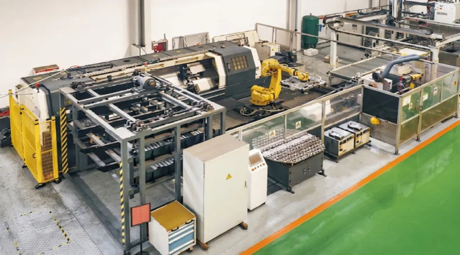
Our production programme covers agricultural gearboxes, worm gear reducers, planetary gear drives, power take-off shafts, hydraulic cylinders, gears, chains, and motors. The entire manufacturing operation carries ISO 9001:2015 certification — a third-party audited quality management framework that governs every process stage from raw material receipt through dispatch. This means buyers in Australia, the UK, the Netherlands, Brazil, Canada, South Korea, and Colombia receive documented evidence of consistent process control without needing to conduct on-site factory audits.
Beyond the standard worm gear reducer gearbox range, our engineering team designs and produces a broad range of industrial and agricultural gearbox assemblies in ductile iron, cast iron, cast steel, precision cast steel, and cast aluminium. In-house machining covers gears, sprockets, worm gears, pulleys, worms, shafts, and both standard and non-standard mechanical parts. Whether you need a single new universal speed worm reducer for an urgent repair or a volume order of worm reducer motor assemblies for an OEM production run, our export and logistics team handles both with equal attention to lead time accuracy and shipment documentation completeness.
For engineers searching for a large universal speed reducer or a white universal speed worm reducer in a specific custom finish, our technical team can advise on available configurations and material options. Our selection guides cover all standard frame sizes and ratios; application-specific questions about worm gear reducer installation, torque arm design, or motor pairing are handled directly by our mechanical engineering staff — not routed through a sales intermediary.
WorkShop



Related Products — One-Stop Drive System Supply
Sourcing the EP-WPWDKA-S universal speed reducer together with matching motor and companion gearbox products from a single supplier simplifies documentation, reduces the number of technical interfaces to manage, and strengthens after-sales support. The products below are engineered to work with the WPWDKA-S series as part of an integrated drive system.

Our IEC-frame موتورهای الکتریکی bolt directly onto the WPWDKA-S motor flange, covering the full 0.12 kW to 15 kW input power range of this universal speed reducer series. Direct flange coupling removes the need for a separate motor adapter plate or flexible coupling, keeping the drive train short, coaxial, and free of alignment-dependent wear points. Motors are stocked in 2-pole and 4-pole configurations at standard IEC frame sizes for fast availability worldwide.

When your application requires a different mounting configuration — solid output shaft, single hollow bore, or vertical input — our complete گیربکس حلزونی programme covers NMRV, WP, WPA, WPWDS, WPWDA, and WPWKV series, all manufactured to the same quality standards and carrying the same IEC motor-flange interface dimensions. Standardising on one supplier for your complete worm gear reducer gearbox range reduces the engineering time spent managing multiple part number families across different machine variants in your catalogue.
سوالات متداول
تدوینگر: PXY