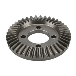
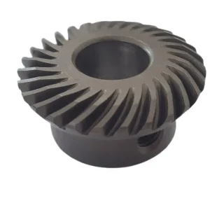
EP-Gigi Bevel Presisi
Itu EP-Gigi Bevel Presisi is a high-accuracy transmission component engineered for intersecting shaft applications in demanding industries. Available in modules from M0.15 to M2.2 and diameters up to 120mm, these gears are manufactured from diverse materials including Steel, Bronze, Aluminum, and POM to meet specific load requirements. They achieve exceptional meshing grades of ISO6, JIS 6, and DIN 6, ensuring smooth and quiet operation. Advanced heat treatments such as carburizing, quenching, and nitriding are applied based on material type to maximize surface hardness and core toughness. Certified under ISO 9001:2008/TS16949, these gears are vacuum-packed for protection and are widely used in automotive, aerospace, medical, and military equipment. Fully customizable via ODM/OEM services, EP delivers precision bevel gears that ensure reliable power transmission in critical mechanical systems.
Dimension: Ø3 mm – Ø120 mm | Module: M0.3 (Range: M0.15 – M2.2) | Material: Metal as customer required
Grades: ISO6 / JGMA 1 / JIS 6 / AGMA 13 / DIN 6 / Din5 / AGMA12 | ODM/OEM | Sample Available
Spesifikasi Teknis
The following table presents the complete specification range of the EP-Precision bevel gear. Parameters confirmed at order stage include material grade, heat treatment, meshing grade, module, tooth count, shaft angle, bore diameter, and surface treatment. OEM drawings and samples are accepted as specification input.
| Parameter | Standard / Reference Value | Customizable Range |
|---|---|---|
| Jenis Gigi | Precision Bevel Gear | Straight / Spiral / Zerol bevel |
| Dimension (OD) | Ø12 mm (reference) | Ø3 mm – Ø120 mm |
| Modul | M0.3 (standard) | M0.15 – M2.2 |
| Material Type | Metal, Steel, Alloy Steel | Bronze, POM, Zinc, Aluminum, Iron, Stainless, Brass, Copper |
| Meshing Grade | ISO6, JGMA 1, JIS 6, AGMA 13 | DIN 6, Din5, AGMA12 |
| Pressure Angle | 20° | 14.5° / custom |
| Sudut Poros | 90° | Non-right-angle on request |
| Perlakuan Panas | Carburizing and quenching | HF quenching, Nitriding, Hardening & tempering |
| Application Sectors | Automotive, Military, Aircraft, Mechanical, Industrial, Medical | — |
| Customized | ODM / OEM | Drawing or sample accepted |
| Sample | Sample available | — |
| Packing | Vacuum-packed with Plastic Tray | Custom packing on request |
| Delivery | DHL & UPS | Freight forwarder accepted |
| Certificate | ISO 9001: 2008 / TS16949 | Material certs, inspection reports on request |
What Is a Precision Bevel Gear?
The EP-Precision bevel gear is a high-accuracy conical gear designed to transmit motion and torque between intersecting shafts — most commonly at 90°, though other shaft angles are achievable depending on the tooth geometry specified. The defining characteristic of a bevel gear is its conical pitch surface: teeth are cut on the face of a truncated cone, and when two mating bevel gears are assembled with their cone apices coinciding at the same point, they transmit rotation smoothly between shafts that would otherwise have no mechanical connection. This directional change capability is what makes the bevel gear indispensable in mechanical systems where power must be redirected — automotive differentials, hand drills, right-angle gearboxes, and robotic joints all rely on bevel gear sets to achieve the shaft arrangement the system requires.
What sets the EP-Precision bevel gear apart from commodity bevel gears is the meshing grade specification. This product is manufactured to ISO6, JGMA 1, JIS 6, AGMA 13, DIN 6, Din5, and AGMA12 accuracy grades — a multi-standard coverage that reflects the breadth of industries served, from automotive and aerospace to medical and military. The diameter range of Ø3 mm to Ø120 mm and module range of M0.15 to M2.2 span the miniature instrument drives common in medical and optical devices through to mid-size industrial gear sets. Material options include metal, bronze, steel, alloy steel, POM, zinc, aluminum, iron, stainless steel, brass, and copper — with the specific grade selected to match the operating environment, load, speed, and regulatory requirements of the application. ODM and OEM programs are both supported, and samples are available before production commitment.
Five Key Advantages of the EP-Precision Bevel Gear
Multi-Standard Precision Grades
The EP-Precision bevel gear is manufactured to simultaneously cover ISO6, JGMA 1, JIS 6, AGMA 13, DIN 6, Din5, and AGMA12 accuracy grades. This multi-standard compliance means a single product family satisfies the supplier qualification requirements of customers in Japan (JIS / JGMA), North America (AGMA), Germany and the EU (DIN / ISO), and international military or aerospace programs with their own derived standards. Engineers in different regions can specify to their local standard and receive a product that meets it — without needing to source from a different supplier for each market.
Broadest Material Selection in Class
Selecting the right material for a bevel gear depends on the load, speed, operating environment, weight budget, and regulatory context. The EP-Precision range covers metal, bronze, steel, alloy steel, POM, zinc, aluminum, iron, stainless steel, brass, and copper — a selection broad enough to address virtually every application context. Automotive differentials need high-alloy steel with carburized tooth flanks; medical instruments need stainless or POM for biocompatibility; marine auxiliary drives need bronze or stainless to resist seawater corrosion. All of these scenarios are addressable from the same product line, with the material confirmed at quotation stage.
Comprehensive Heat Treatment Options
Heat treatment for the EP-Precision bevel gear is selected to match the material and application — not applied as a one-size default. The available processes include carburizing and quenching, high-frequency (induction) quenching, nitriding, hardening, and tempering. Carburizing with quench produces the highest tooth surface hardness (HRC 58–62) over a tough core — the standard for automotive and heavy-industrial bevel gear applications. Nitriding achieves good surface hardness at lower distortion, preserving dimensional accuracy on complex precision parts. Induction hardening is applied where only selected surfaces need hardening. The right process is confirmed based on the material grade, required hardness profile, and part geometry.
Wide Dimensional Range — Ø3 mm to Ø120 mm
The Ø3 mm lower bound places this bevel gear in reach of miniature instrument drives — watchmaking, optical instruments, micro-motor actuators, and small medical devices — while the Ø120 mm upper bound covers solid mid-size industrial applications. The M0.15 to M2.2 module range spans the same spectrum. Having a single supplier capable of delivering precision bevel gears across this full size range simplifies the supply chain for OEM programs that use bevel gear stages at multiple points in a product — a small instrument-scale bevel and a larger input-stage bevel can both come from the same manufacturing source, with consistent quality documentation and material traceability.
ODM/OEM Flexibility & Sample-First Policy
Both OEM (manufacturing to customer drawings) and ODM (design and manufacture to performance specification) programs are supported. For new product development, the sample-first policy means a dimensionally verified prototype bevel gear can be supplied and tested in the customer's assembly before production volume is authorized. Packing is vacuum-sealed with plastic tray for precision gear protection during transit, and delivery is via DHL and UPS for reliable international shipment. This end-to-end service — from design assistance through prototyping to production delivery — removes the overhead of managing multiple vendors across the precision bevel gear development cycle.
How Does a Bevel Gear Work?
The fundamental operating principle of a bevel gear follows from its conical geometry. Each gear in a bevel pair has teeth cut on the surface of a cone — the pitch cone — and when two mating bevel gears are assembled correctly, their pitch cones touch along a common element (a line from apex to pitch point) while their cone apices coincide at a single point. As one gear rotates, its tooth flanks exert a force on the mating tooth flanks. Because the tooth surfaces are defined by the involute or octoid profile in the plane perpendicular to the pitch cone, the velocity ratio between the two shafts remains constant throughout the mesh cycle — the fundamental requirement for smooth power transmission without oscillating speed.
In a straight bevel gear, the tooth traces are straight lines that, if extended, would pass through the cone apex. Engagement of each straight tooth pair is abrupt — the full tooth width comes into contact simultaneously — which limits the pitch-line velocity and produces more noise than curved-tooth alternatives. Spiral bevel gears address this by cutting the teeth along a curved path (typically an Archimedean spiral or involute spiral), so engagement progresses gradually along the tooth, increasing the contact ratio and reducing the dynamic mesh force. The EP-Precision bevel gear covers both straight and spiral configurations depending on the application requirement, with the module range M0.15 to M2.2 covering both fine-pitch precision drives and moderate industrial stages.
The gear ratio of a bevel gear pair is determined by the tooth count ratio: dividing the number of teeth on the driven gear by the number of teeth on the driving gear gives the ratio. For a right-angle pair where the shaft angle is exactly 90°, the pitch cone half-angles of the two gears are complementary — they sum to 90° — and the ratio is set entirely by the tooth counts. This simple relationship makes the bevel gear easy to specify for a given speed reduction or increase requirement, and it is one of the reasons the bevel gear has remained the dominant solution for right-angle shaft arrangements in mechanical engineering for more than a century.
Material Selection & Heat Treatment for Precision Bevel Gears
Choosing the correct material for a precision bevel gear is one of the most consequential decisions in the gear design process. The material determines the maximum achievable tooth surface hardness, the core toughness (resistance to tooth root fracture), the machinability (which affects achievable precision grade and production cost), and the environmental resistance (corrosion, temperature, chemical exposure). The EP-Precision bevel gear range offers metal, bronze, steel, alloy steel, POM, zinc, aluminum, iron, stainless steel, brass, and copper — each suited to a different cluster of applications.
For high-torque, high-speed applications — automotive differentials, aircraft auxiliary gearboxes, military vehicle drivetrains — case-hardening alloy steels such as 20CrMnTi or 8620 are typically specified. These grades develop a hard, fatigue-resistant tooth surface (HRC 58–62 by carburizing and quenching) over a tough, impact-resistant core. After heat treatment, gear grinding corrects the dimensional distortion introduced by the quench, restoring the tooth profile to the declared DIN 6 or AGMA 13 precision grade. Bronze bevel gears are the traditional choice for marine and hydraulic applications where corrosion resistance and a low galling tendency against steel pinions are essential — the bronze gear wears preferentially, protecting the more expensive pinion. Stainless steel and POM bevel gears serve medical and food-processing environments where contamination risk from metal debris or rust is unacceptable.
The heat treatment options available for this product — carburizing and quenching, high-frequency quenching, nitriding, hardening, and tempering — are not interchangeable; the selection depends on the material grade and the hardness profile required. Nitriding, for example, produces an exceptionally hard surface layer (up to 1100 HV) with minimal distortion, making it suitable for precision bevel gears where the tooth geometry cannot be corrected by grinding after heat treatment due to accessibility or cost constraints. All heat treatment processes are documented in the manufacturing record, and hardness reports can be supplied as part of the delivery documentation for regulated industries.
Precision Bevel Gear Design & Types
Understanding the main configurations within the bevel gear family helps in selecting the right tooth form for a given application. Straight bevel gears have teeth that lie along straight radial lines on the pitch cone surface. They are the simplest to manufacture and the most cost-effective, and they perform well at low-to-moderate pitch-line velocities — up to approximately 5 m/s in precision grades. Above that speed, the abrupt tooth engagement generates noise and dynamic loads that make straight bevel gears less suitable than their curved-tooth counterparts. Straight bevel gear sets are widely used in hand tools, low-speed industrial right-angle drives, and agricultural power take-off shafts across Europe, Australia, and North America.
Spiral bevel gears have curved teeth with a helix angle — typically between 25° and 35° — that causes tooth engagement to progress gradually from one end of the tooth face to the other, similar to the way a helical gear engages on a parallel shaft. The result is a higher contact ratio, smoother operation, and a higher practical pitch-line velocity compared to straight bevel gears. The trade-off is that spiral bevel gears generate axial thrust on both shafts, which must be accommodated by the bearing arrangement. Spiral bevel gears are the standard for automotive differentials, rear axle drives, and high-speed industrial angle gearboxes globally.
Zerol bevel gears — sometimes referenced as "what is zero bevel gear" in engineering queries — are a specific form of curved-tooth bevel gear where the spiral angle at the pitch cone midpoint is zero. The tooth is curved but lies in the plane perpendicular to the pitch cone axis at mid-face, giving Zerol gears the smooth mesh of spiral bevel gears while generating lower axial thrust than a true spiral bevel. This makes them suitable for retrofit into existing housings originally designed for straight bevel gears, without requiring the bearing upgrade that full spiral bevel thrust loads would demand. The EP-Precision bevel gear can be produced in any of these tooth forms, with the selection confirmed based on the operating speed, noise requirement, and existing bearing arrangement of the customer's design.
Precision Bevel Gear Applications
Itu bevel gear advantages — direction change between intersecting shafts, high load capacity in compact form, and the ability to achieve almost any shaft angle — make the bevel gear one of the most widely deployed gear types across both heavy industry and precision engineering. The following scenarios illustrate where the EP-Precision bevel gear is most frequently specified.
Automotive — Differentials & Axle Drives
The automotive differential is the most recognizable bevel gear application in the world. Four bevel gears — two side gears and two spider (pinion) gears — mesh within the differential housing to allow the driven wheels to rotate at different speeds during cornering. The EP-Precision bevel gear range, with its alloy steel material options and carburizing heat treatment capability, serves automotive-grade differential bevel gear requirements from passenger car differentials through to heavy commercial vehicle rear axles. TS16949 certification supports automotive supplier qualification in the US, Germany, Japan, and South Korea.
Aerospace & Military Systems
Aircraft auxiliary gearboxes, helicopter tail rotor drives, and military vehicle transfer cases all use bevel gear stages where the intersection of drive shafts at non-parallel angles cannot be avoided. Precision bevel gears in these applications are specified to the tightest available meshing grades — AGMA 13 or ISO6 — and are manufactured from high-alloy steel with carefully controlled case depth and core hardness. The material and process documentation requirements of aerospace and defense programs are met by our ISO 9001 and TS16949 certification framework, which supports full material traceability and dimensional inspection reporting.
Medical Devices & Surgical Equipment
Miniature precision bevel gears in stainless steel or POM drive the directional mechanisms in endoscopic instruments, surgical robots, and imaging device positioning stages. The Ø3 mm lower dimensional bound of this product range reaches the scale of instruments used in minimally invasive surgery, where the gear stage must fit within the instrument shaft diameter while delivering accurate, backlash-controlled motion. Stainless steel material grades are autoclave-compatible; POM variants are suitable for chemical sterilization. The availability of samples before production authorization is especially valued by medical device developers in the US, Germany, and Japan who need to validate regulatory-compliant assemblies.
Hand Tools & Power Equipment
Right-angle hand drills, angle grinders, and power screwdrivers all require a bevel gear stage to turn the rotational output of the motor through 90° to the tool chuck or grinding disc. In these applications the bevel gear must handle intermittent shock loads from the tooling, operate at moderate speeds without generating excessive noise, and fit within the compact housing dictated by the tool's ergonomics. Steel or alloy steel bevel gears with induction-hardened tooth flanks serve well in this category, and the Ø10 mm to Ø40 mm size range within this product covers most consumer and professional-grade power tool applications in markets across North America, Europe, Australia, and Southeast Asia.
Industrial Right-Angle Gearboxes
Industrial bevel gear sets in right-angle gearboxes serve mixing equipment, conveyor systems, packaging machinery, and pump drives where the motor and driven shaft must be arranged at 90° to each other. The EP-Precision bevel gear in steel or bronze covers the industrial speed reducer segment from compact instrument-scale gearboxes through to mid-size industrial units. Bronze bevel gears mating against steel pinions are a durable, self-lubricating combination favored in food processing, marine auxiliary, and general industrial applications across the UK, Europe, and the Asia-Pacific region where maintenance intervals are long and gear replacement is disruptive.
Robotics & Automation
Robotic joint actuators increasingly specify precision bevel gears at the wrist and end-of-arm stages where a direction change between the forearm and end-effector cannot be achieved by a parallel-shaft gear train. The compact, high-accuracy bevel gear sets in the M0.15 to M0.5 module range serve collaborative robot joint drives where the gear stage must be as small and light as possible while maintaining the positional accuracy demanded by precision assembly and pick-and-place tasks. Stainless steel or alloy steel bevel gears with ground tooth profiles and tight backlash control are the standard specification for automation bevel gear applications in German, Japanese, and US robotics programs.
Bevel Gear vs Spur Gear — Choosing the Right Configuration
The most common comparison engineers face when specifying a gear stage is bevel gear vs spur gear, and the answer depends almost entirely on the shaft arrangement. Spur gears and helical gears transmit power between parallel shafts — shafts whose axes run side by side without intersecting. A bevel gear is required whenever the two shafts intersect at an angle, which in the vast majority of applications means 90°. There is no practical substitute for a bevel gear in a right-angle drive: worm gear pairs can achieve 90° shaft angles but at lower efficiency (typically 60–90% versus 95–99% for a bevel gear pair), higher sliding friction, and much lower pitch-line velocity capability.
Within right-angle drives, the choice between a bevel gear and a worm gear is often decided by efficiency requirement and ratio. Worm drives achieve high single-stage ratios (10:1 to 100:1) in compact form but at the efficiency penalty noted above; bevel gear pairs achieve lower single-stage ratios (typically 1:1 to 5:1) with higher efficiency and bidirectional backdrivability. When a designer needs a right-angle drive with a ratio above 5:1 at high efficiency, a spiral bevel gear first stage is often combined with a helical second stage, giving the direction change and the ratio in two compact stages. The EP-Precision bevel gear range supports both standalone right-angle stages and multi-stage gearbox integration.
Related Products — Complete Drivetrain Compatibility
Our manufacturing range extends well beyond the bevel gear to cover the parallel-shaft gear stages and linear motion components that typically appear upstream or downstream of a bevel drive. Sourcing these components from a single factory simplifies engineering documentation and eliminates the compatibility uncertainty that multi-vendor drivetrain assemblies introduce.
Roda Gigi Heliks Ganda
Where the bevel gear stage handles the direction change in a drivetrain, a double helical gear stage often provides the speed reduction on the parallel shaft sections leading to or from the bevel. Our precision double helical gears are manufactured to the same quality standards as the EP-Precision bevel gear range — DIN and AGMA accuracy grades, matched material and heat treatment documentation, and ISO 9001 quality management throughout. The self-balancing axial thrust of the double helical gear eliminates the need for thrust bearings on the parallel shaft stages, simplifying the overall gearbox design when combined with the bevel stage. Both products can be specified from the same engineering contact, drawing on the same quality system for consistent documentation across the drivetrain.

Rak Perlengkapan
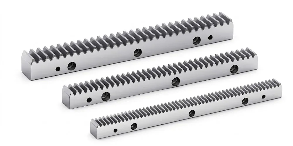
When a drivetrain converts rotary motion to linear translation downstream of the bevel gear direction change, a precision gear rack paired with a mating helical pinion gear delivers the linear output stage. Our gear rack range is manufactured in carbon steel and stainless steel in metric module, with hobbed or ground tooth profiles compatible with our helical gear pinion range. CNC gantry systems, automated guided vehicles, machine tool carriages, and heavy-duty sliding mechanisms all use rack-and-pinion linear stages fed from gearboxes that may include a bevel gear input stage for motor mounting flexibility. Specifying the bevel gear, helical gear stages, and gear rack from a single manufacturing source ensures consistent module, pressure angle, and material documentation across the complete drive system — a practical advantage for OEM engineering teams in Europe, North America, and Australia managing complex drivetrain projects.
Tentang Fasilitas Manufaktur Kami
With more than ten years of engineering expertise in precision mechanical components and power transmission systems, our factory serves industrial customers across the automotive, aerospace, medical, agricultural, and general manufacturing sectors worldwide. Our product portfolio spans agricultural gearboxes, worm gear reducers, planetary gear drives, power take-off shafts, hydraulic cylinders, gears, chains, and motors — the full breadth of a serious mechanical transmission supplier.
We design and produce a comprehensive range of industrial and agricultural gearbox assemblies using ductile iron, cast iron, cast steel, precision cast steel, and cast aluminum, alongside machined gears, sprockets, worm gears, pulleys, worms, shafts, and both standard and non-standard mechanical parts. Our facility holds ISO 9001:2008 and TS16949 certification — the automotive quality standard that confirms our process discipline meets the requirements of Tier 1 and Tier 2 automotive supplier programs. Precision bevel gear production is carried out on CNC gear cutting and grinding machines under the full quality system, with dimensional inspection records and material traceability documentation available for every production batch. Customers sourcing precision bevel gears for regulated industries — automotive, aerospace, medical — can request full documentation packages as part of their standard order. Global delivery via DHL and UPS ensures reliable delivery to customers in Germany, the US, Japan, Australia, the Middle East, and Southeast Asia.
Pertanyaan yang Sering Diajukan
Editor: PXY