
DC Motor Series
Motor Pintu Angkat
The definitive guide to hydraulic liftgate drive motors — how they work, what they’re made of, how to choose the right specification, and a full overview of our production range covering 12V and 24V platforms from 2000W to 2800W.
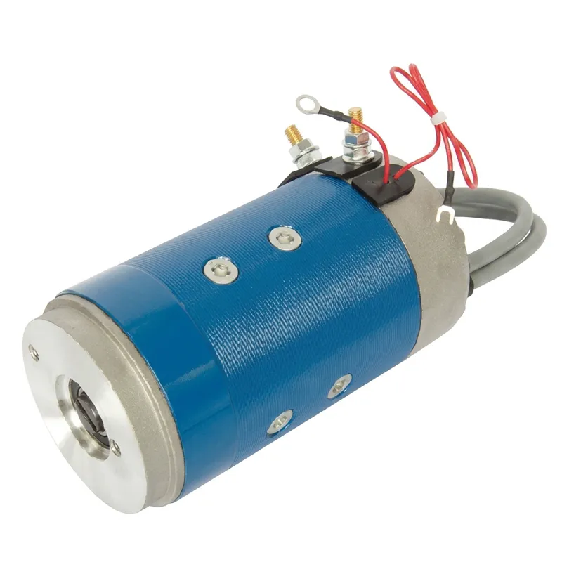
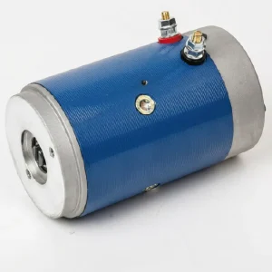
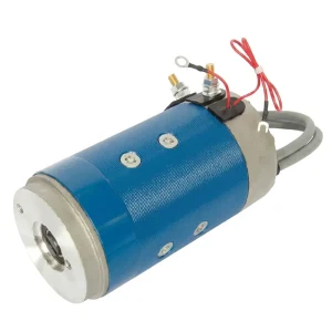
Mengenai Motor Pintu Angkat
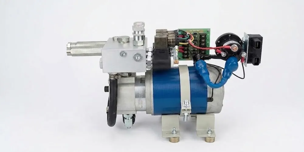
A lift gate motor is a DC electric motor purpose-built to drive the hydraulic pump unit in a commercial vehicle tailgate system. When the operator triggers the gate-up command, the motor spins the pump — pressurizing hydraulic fluid, extending the lift ram, and raising the platform. On descent, a controlled valve releases hydraulic pressure to lower the gate at a safe, managed rate.
Unlike general-purpose DC motors, a liftgate motor is designed around a specific duty cycle — typically short, high-current bursts separated by adequate rest periods. This intermittent pattern (expressed as S2 or S3 duty, e.g. 2min-10%ED or 8min-10%ED) is what allows the motor to deliver very high power output relative to its physical size, without accumulating damaging heat over a working shift.
12V vs 24V Liftgate Motor
12V Platform
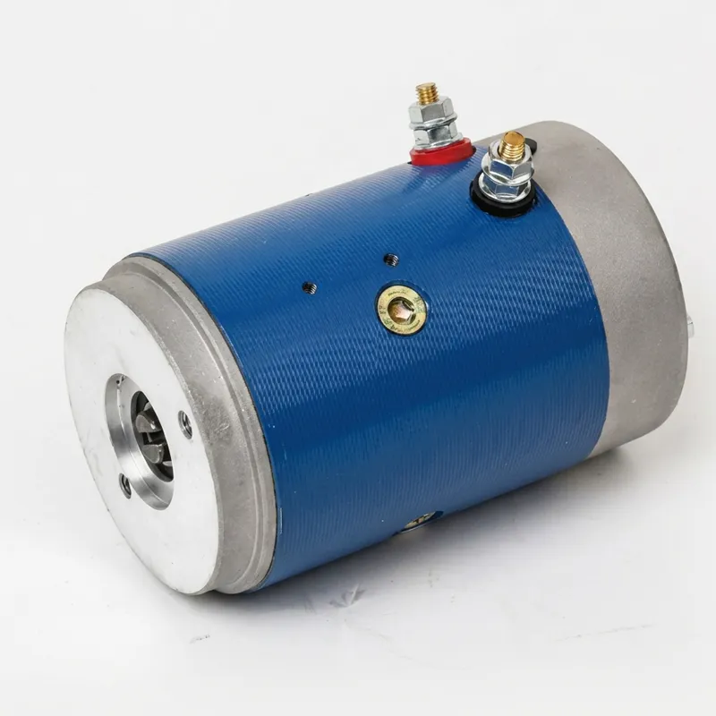
24V Platform
Lift Gate Motor Series — Complete Specifications
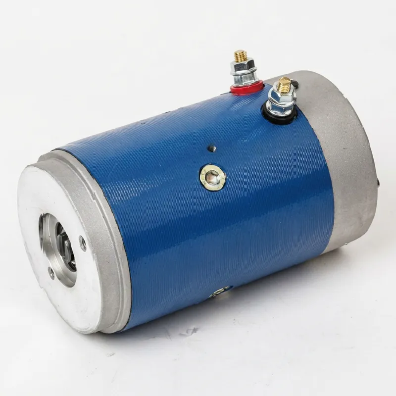
Our lift gate motor range covers both 12V and 24V platforms, with power outputs from 2000W to 2800W. All models are rated for car tailgate / liftgate application and carry IP54 weatherproofing and Class F insulation as standard.
| Voltan (V) | Kuasa (W) | Semasa (A) | Tork (N·m) | Kitaran Tugas | Insulation | Penarafan IP | Teeth | Putaran | Config. Options |
|---|---|---|---|---|---|---|---|---|---|
| 12 | 2000 | 220 | 6 | 2min-7%ED | F | IP54 | 2 | CW | 24V, 48V |
| 12 | 2200 | 260 | 10 | 8min-10%ED | F | IP54 | 2 | CW | — |
| 24 | 2200 | ≤135 | 7 | 2.5min-9%ED | F | IP54 | 2 | CW | 12V, 48V |
| 24 | 2200 | 125 | 9 | 2min-10%ED | F | IP54 | 2 | CW | — |
| 24 | 2800 | 165 | 9 | 5min-13%ED | F | IP54 | 2 | CW | — |
All models: Car tailgate / Lift gate application. Mounting and shaft interfaces available on request. Custom configurations supported.
Lift Gate Motor’s Components
Permanent Magnet Stator
The stator provides the fixed magnetic field that the armature rotates within. In this motor type, the field is generated by permanent magnets — typically high-energy ferrite or rare-earth grade — fixed to the inside of the motor housing. These magnets require no electrical supply and produce no field winding losses, contributing directly to the motor’s efficiency.
Angker (Rotor)
The rotating core of the motor. It consists of a silicon steel lamination stack wound with copper conductors — the armature windings. When current flows through these windings in the presence of the stator’s magnetic field, electromagnetic force produces rotation. Laminating the core in thin silicon steel sheets minimizes eddy current losses and keeps the armature running efficiently at operating speed.
Commutator & Brush Assembly
The commutator is a segmented copper ring on the armature shaft that reverses current direction in the windings as the rotor turns — maintaining consistent torque direction. Carbon-copper composite brushes ride on the commutator surface, carrying current from the external circuit into the rotating windings. Brush condition is one of the primary wear indicators in a liftgate motor’s service life.
Motor Housing
The structural shell that contains and protects the internal components. Cast from precision aluminum alloy for most liftgate motor sizes, the housing simultaneously provides rigidity, corrosion resistance, and — critically — a thermal conduction path for heat generated in the windings. The IP54 sealing of our motors is achieved through careful design of the housing end-bells, brush holder seals, and shaft seal interfaces.
Aci & Galas Output
The hardened, precision-ground output shaft transmits rotational force to the hydraulic pump coupling. Pre-greased sealed ball bearings at both ends of the armature shaft support the radial and axial loads generated during high-torque pump drive operation. Bearing selection is calibrated to the expected load profile — liftgate motors see significant radial loading from direct-coupled gear pumps, making bearing durability a key design consideration.
Class F Winding Insulation
All armature windings are coated with Class F insulating varnish, typically applied by vacuum pressure impregnation to ensure complete penetration into the winding pack. Class F is rated to 155°C maximum winding temperature — providing a substantial margin above the temperatures generated during the motor’s rated duty cycle. This insulation class is what allows the motor to sustain high-current operation repeatedly without progressive degradation of winding integrity.
How to Select the Right Lift Gate Motor
Selecting the correct liftgate motor involves matching five key parameters to your specific vehicle and application requirements. Working through these in order will lead you to the correct specification without over- or under-specifying.
This is non-negotiable — the motor voltage must match the vehicle's battery system. Light commercial vehicles (vans, small delivery trucks) are typically 12V. Heavier commercial vehicles, European long-haul trucks, and most refrigerated transport operate on 24V. Using a 12V motor on a 24V system will cause immediate winding failure.
Power requirement is determined by the hydraulic pump's drive specification and the liftgate's rated payload capacity. Standard commercial liftgates (500–2000kg payload) are typically served by 2000–2200W motors. Higher-capacity or faster-cycle systems may benefit from a 2800W unit. When replacing an existing motor, match or slightly exceed the original power rating.
The motor must physically couple to the hydraulic pump with the correct shaft diameter and coupling geometry, and mount to the pump body or sub-frame with compatible bolt patterns. Always reference the motor's outline drawing (available from us on request) and compare against the pump's motor mounting specification. Incorrect shaft dimensions require adapters and add failure points.
All motors in our liftgate range rotate clockwise (CW) when viewed from the output shaft end — matching the standard configuration of the majority of commercial liftgate hydraulic pump units. If your pump requires counter-clockwise rotation, contact us; this can be accommodated through customization. Fitting a motor with the wrong rotation direction will cause the pump to work in reverse — no pressure will be generated and the gate will not raise.
IP54 is the standard sealing level for all our liftgate motors and covers the typical environmental exposure of under-chassis mounting. If the vehicle operates in particularly harsh environments (repeated high-pressure wash-downs, chemical exposure, extreme cold climates), discuss your specific conditions with us — we can advise on additional protection measures or alternative sealing configurations where appropriate.
Maintenance, Diagnostics & Knowing When to Replace
Lift gate motors are robust components, but they do wear over time. Recognizing early warning signs prevents unexpected vehicle downtime.