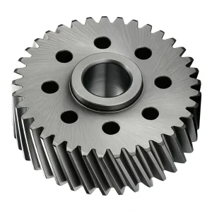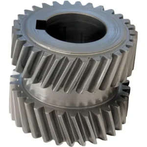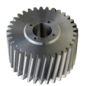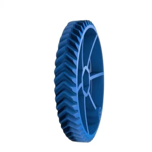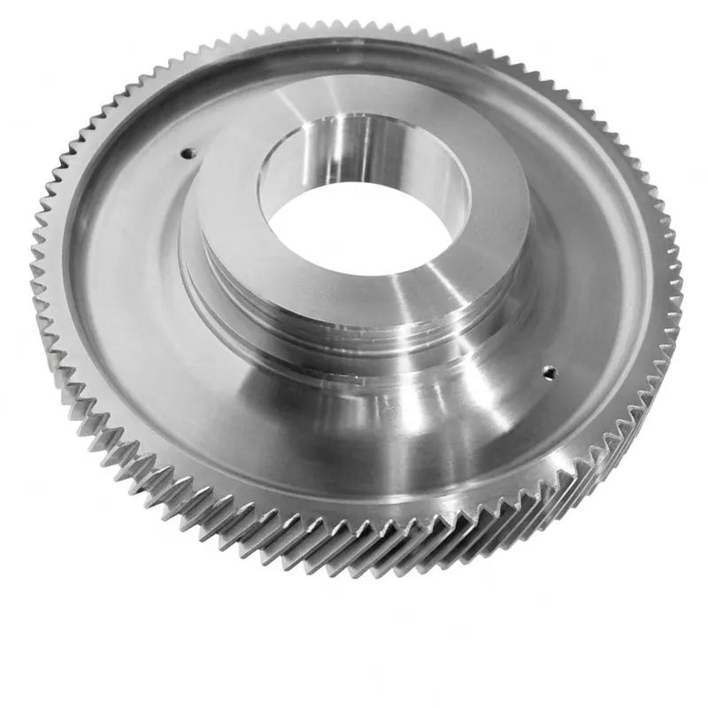
EP-High Speed Train Locomotive Flank Helical Gear
The EP-High Speed Train Locomotive Flank Helical Gear represents one of the most technically demanding applications of helical gear manufacturing. Designed specifically for rail traction gearboxes in high-speed passenger and freight locomotive systems, this gear must sustain consistent performance across the full operational speed envelope of modern railway rolling stock — conditions that expose every aspect of gear design and manufacture to relentless scrutiny. The tooth form is involute with a pressure angle of 20°, a module of Mn=4, a tooth count of Z=132, and a helix angle of β=18°, parameters that together define the helical gear design optimised for smooth, high-speed traction drive engagement.
The base material is 17CrNiMo6, a case-hardening alloy steel recognised internationally as the benchmark for heavy-duty gear applications where a combination of surface hardness and core toughness is non-negotiable. The manufacturing sequence — forging, lathing, hobbing, carburizing, external grinding, and tooth grinding — represents the full complement of precision operations needed to achieve DIN 3962 Class 6 accuracy. That accuracy grade, when applied to a helical gear of this module and tooth count, demands extremely tight tolerances on tooth profile, helix deviation, pitch error, and runout.
Rail Traction / Precision Power Transmission
Precision-forged involute helical gear engineered to DIN 3962 Class 6 standards — purpose-built for high-speed rail traction gearboxes, delivering consistent performance at extreme rotational speeds, tight dimensional tolerances, and demanding duty cycles across global rail networks.
Material: 17CrNiMo6
Gear Type: Mn=4, Z=132, β=18°
Quality: DIN 3962 Class 6
Pressure Angle: 20°
ISO 9001:2015 Certified
Technical Specification & Machining Capabilities
The tables below present the basic gear data for this locomotive flank helical gear together with the full gear and spline machining capabilities of the production facility. These capability ranges define the envelope within which custom made helical gears and associated spline forms can be manufactured to order. All values represent current installed machine capacity; individual project requirements are assessed against these limits before order confirmation.
Gear Basic Data
| Parâmetro | Valor |
|---|---|
| Gear Tooth Shape | Involute |
| Material da engrenagem | 17CrNiMo6 |
| Gear Process | Forging → Lathing → Hobbing → Carburizing → External Grinding → Tooth Grinding |
| Pressure Angle | 20° |
| Quality Level | DIN 3962 Class 6 |
| Gear Type (Specific) | Mn=4, Z=132, β=18° |
Capabilities — Internal Gears and Internal Splines
| Parâmetro | Milling | Shaping | Tooth Grinding |
|---|---|---|---|
| Maximum O.D. | 2,500 mm | 2,500 mm | 2,500 mm |
| Minimum I.D. | 650 mm | 50 mm | 100 mm |
| Maximum Face Width | 500 mm | 500 mm | 500 mm |
| Maximum Diametral Pitch | D.P. 1 | D.P. 1 | DP 0.5 |
| Maximum Module | 26 mm | 26 mm | 45 mm |
| AGMA / DIN Level | DIN Class 8 | DIN Class 8 | DIN Class 4 |
| Tooth Surface Finish | Ra 3.2 | Ra 3.2 | Ra 0.6 |
| Maximum Helix Angle | ±22.5° | ±22.5° | ±45° |
Capabilities — External Gears and External Splines
| Parâmetro | Hobbing | Milling | Tooth Grinding |
|---|---|---|---|
| Maximum O.D. | 1,250 mm | 2,500 mm | 2,500 mm |
| Minimum O.D. | 20 mm | 200 mm | 20 mm |
| Maximum Face Width | 500 mm | 500 mm | 1,480 mm |
| Maximum Diametral Pitch | D.P. 1 | D.P. 1 | DP 0.5 |
| Maximum Module | 26 mm | 26 mm | 45 mm |
| AGMA / DIN Level | DIN Class 8 | DIN Class 8 | DIN Class 4 |
| Tooth Surface Finish | Ra 3.2 | Ra 3.2 | Ra 0.6 |
| Maximum Helix Angle | ±45° | ±45° | ±45° |
Five Key Advantages of This Locomotive Flank Helical Gear
① DIN 3962 Class 6 Precision — Rail-Grade Accuracy
Achieving DIN 3962 Class 6 on a helical gear of Mn=4 and Z=132 demands that every measurable geometric parameter — tooth profile deviation, helix angle error, total cumulative pitch error, and radial runout — is held to tolerances measured in micrometres. At the pitch-line velocities typical of high-speed rail traction drives, any departure from this accuracy level produces vibration excitation that is not merely uncomfortable but structurally damaging to both the gearbox and the rail vehicle bogie. The helical gear machining sequence culminating in precision tooth grinding is the manufacturing step that makes Class 6 consistently achievable, and it is the step that most separates a rail-specification helical gear from a standard industrial gear product.
② 17CrNiMo6 Case-Hardening Steel — Optimal Core-Surface Balance
The selection of 17CrNiMo6 as the helical gear material for locomotive applications is not arbitrary. This nickel-chromium-molybdenum case-hardening steel develops a carburised surface layer with hardness typically in the range of 58–62 HRC while retaining a tough, ductile core capable of absorbing the shock loads and torque reversals inherent in rail traction service. The nickel content in particular contributes to the low-temperature toughness that is important in geographic regions where locomotives operate through severe winters — notably Northern Europe, Canada, and Russia. No steel helical gear material combination delivers this balance more reliably at the load and speed levels of high-speed rail than 17CrNiMo6.
③ Optimised 18° Helix Angle — Smooth Power Flow at Speed
The helix angle of a helical gear directly governs the overlap ratio — the fraction of the tooth face width engaged in mesh at any instant. At β=18°, the overlap ratio on this Z=132 gear is sufficient to ensure that multiple teeth share the transmitted load simultaneously at all operating speeds, eliminating the load impulses that characterise spur gear mesh and reducing the helical gear noise signature to levels compatible with passenger comfort standards. Traction gearboxes in European high-speed rail systems routinely specify helix angles in the 15°–22° range for exactly this reason, and the 18° selection on this product sits comfortably within that established design practice for locomotive helical gear design.
④ Full-Process Manufacture — Single-Source Quality Control
The complete manufacturing sequence for this helical gear — from forging the blank through to final tooth grinding and dimensional inspection — is executed within one facility under the same ISO 9001:2015 quality management system. This single-source approach eliminates the inter-supplier material and dimensional discrepancies that can undermine gear quality when different operations are subcontracted to different providers. Every heat treatment batch is documented, every grinding pass is logged, and every finished helical gear is measured on a CNC gear-measuring machine before release. For buyers sourcing replacement helical gear sets for in-service locomotives, this traceability provides the confidence that a replacement gear will match the original specification in every measurable respect.
⑤ Broad Machining Capability — Internal, External, and Custom Configurations
Beyond the specific locomotive flank helical gear described here, the manufacturing facility supports a comprehensive range of gear and spline geometries. External helical gear sets can be produced by hobbing to a maximum O.D. of 1,250 mm, by milling to 2,500 mm, and by tooth grinding to 2,500 mm outer diameter — with face widths reaching 1,480 mm on ground gears. Internal helical gear and spline forms are equally supported, with shaping capability down to 50 mm internal diameter. This breadth of machining capability makes the facility a genuinely capable source for custom made helical gears across the full size range relevant to rail, industrial, and energy sector applications worldwide, including inch helical gears for markets that have not yet transitioned fully to metric standards.
How This Helical Gear Works in a Locomotive Traction Drive
A locomotive traction gearbox takes the high-speed, relatively low-torque output of a traction motor and converts it into the lower-speed, high-torque rotation required to drive the wheel axle at traction conditions. The helical gear set at the heart of this reduction — typically a pinion on the motor shaft meshing with a larger wheel gear on the axle — must perform this function smoothly across a wide speed range, from near standstill during departure to maximum track speed during line running. The involute tooth form of this helical gear, combined with the 20° pressure angle, ensures that the theoretical contact point between meshing teeth moves along a straight line of action, maintaining a constant velocity ratio and transmitting torque without the cyclic speed variations that afflict non-involute gear forms.
As the helical gear rotates, each tooth enters mesh progressively across its face width — a consequence of the 18° helix angle. This gradual engagement means that at any given instant, the transmitted load is shared across a portion of one tooth and a portion of the adjacent tooth. The effective contact ratio is therefore higher than the geometric profile contact ratio alone, and the load per unit tooth area is correspondingly reduced. At the pitch-line velocities of high-speed rail service — commonly exceeding 40 m/s in the traction gear mesh — this load distribution is what prevents the tooth face pressure spikes that would initiate pitting fatigue in a lower-quality helical gear.
The carburised and ground tooth flanks of this helical gear sustain an elastohydrodynamic oil film during operation. Traction gearboxes are pressure-lubricated, and the film thickness at the tooth contact zone is maintained by the combination of pitch-line velocity and lubricant viscosity. At rail operating temperatures — which can range from arctic cold to summer desert conditions on international services — lubricant selection must be matched to the gear's operating speed and the ambient temperature range. This is a detail often overlooked by buyers who focus exclusively on the helical gear geometry but is equally important in determining whether a traction gearbox achieves its design life between planned overhauls.
The interaction between this helical gear and the mating pinion produces a modest axial thrust force — the geometrically inevitable consequence of the helix angle. In a locomotive traction gearbox, this axial force is typically absorbed by angular-contact or tapered roller bearings positioned to react axial loads from both the helical gear wheel and the motor pinion. The bearing arrangement is designed specifically around the known axial force magnitude from the helical gear geometry, which is why replacement gears must precisely match the original helix angle specification: any deviation changes the axial load and can lead to premature bearing failure even when the helical gear itself is dimensionally acceptable.
Material Selection & Manufacturing Quality
The choice of 17CrNiMo6 steel for this locomotive flank helical gear reflects decades of accumulated experience in rail traction gear manufacture. This low-alloy case-hardening steel is specified by rail vehicle builders across Europe, Asia, and North America because its metallurgical properties align precisely with the demands of high-cycle, high-contact-stress gear applications. The composition — nominally 0.17% carbon, 1.5–1.8% chromium, 1.4–1.7% nickel, and 0.25–0.35% molybdenum — produces a hardenable surface layer with excellent resistance to contact fatigue (pitting) and tooth bending fatigue, while the nickel and molybdenum together ensure the core retains significant impact toughness even after carburising.
O helical gear manufacturing process for this locomotive application follows a strict sequence. Forging establishes the grain flow aligned with the gear geometry, which is mechanically superior to a machined-from-bar approach for high-load gears. Rough and finish lathing brings the blank to the dimensional envelope required for tooth generation. Hobbing produces the involute tooth profile to initial accuracy, followed by carburising — a gas or vacuum atmosphere treatment that diffuses carbon into the tooth surface to a controlled depth, typically 0.8–1.5 mm depending on module. After carburising and hardening, the gear undergoes external grinding to restore the bore and datum surfaces to final dimensions before tooth grinding brings the tooth flanks to DIN 3962 Class 6 accuracy. Each step is documented, and the final helical gear measurement report covers profile deviation, helix deviation, pitch error, and runout against the drawing tolerances.
For engineers evaluating this helical gear against alternatives, the key differentiator is the tooth grinding step. A hobbed-and-hardened helical gear — without subsequent grinding — will typically achieve DIN Class 8 at best, and thermal distortion from carburising frequently degrades it further. Only by grinding the hardened tooth flanks can DIN Class 6 be reliably and consistently achieved on a gear of this module and tooth count. The tooth surface finish resulting from precision grinding (Ra 0.6 on ground flanks versus Ra 3.2 on hobbed or milled flanks) is equally significant: smoother flanks support a thicker EHD oil film at a given speed and viscosity, directly improving the gear's resistance to scuffing failure under high-load, low-speed starting conditions in heavy freight locomotive service.
Application Sectors
O helical gear design philosophy and manufacturing capabilities demonstrated by the locomotive flank product extend naturally into a broad range of high-demand application sectors. The combination of precision tooth grinding, high-grade alloy steel, and rigorous dimensional verification makes this helical gear family suitable wherever power, speed, and reliability requirements converge at the upper end of industrial norms.
High-Speed Passenger Rail
This is the primary application for which the locomotive flank helical gear was engineered. High-speed passenger trains operating at 200–350 km/h on European, East Asian, and North American intercity networks demand traction gearboxes that run continuously at elevated pitch-line velocities for millions of kilometres between overhauls. The DIN 3962 Class 6 precision and the Ra 0.6 tooth surface finish achieved by grinding are essential at these speeds — not luxury specifications. Rail authorities in Japan, Germany, France, Spain, and the UK all specify precision-ground helical gear sets for mainline high-speed rolling stock, and the performance requirements from these networks set the global benchmark for this helical gear type.
Electric & Diesel Locomotive Freight Service
Heavy freight locomotives impose a different load profile on the traction helical gear set: lower maximum speeds but higher sustained torques, frequent heavy starting cycles, and operation in environments ranging from Canadian winters to Australian desert summers. The 17CrNiMo6 core toughness — maintained through careful carburising and quenching practice — is particularly important in freight applications where overload incidents during locomotive coupling and emergency braking can subject the helical gear tooth roots to impact stresses well above the calculated design load. Freight railway operators in North America, Australia, and Eastern Europe are among the largest consumers of replacement locomotive helical gear sets globally.
Urban Rail & Metro Systems
Metro and light rail traction gearboxes share the precision requirement of mainline rail but are subjected to far higher start-stop cycle frequencies — some urban rail systems operate up to 30 cycles per hour per vehicle. This cyclic loading accelerates tooth flank contact fatigue if surface hardness, case depth, or helical gear accuracy are below specification. Urban rail operators in Southeast Asia, the Middle East, and South America have significantly expanded their metro networks over the past decade, generating sustained demand for high-quality traction helical gear replacements and new equipment sets. The ability to produce custom made helical gears to specific car builder drawings makes this facility a relevant supplier for both OEM and aftermarket metro gearbox procurement.
Industrial High-Speed Drives
The same involute helical gear geometry, material specification, and precision grinding capability that qualifies this product for rail traction service also addresses the needs of high-speed industrial drives. Centrifugal compressor gearboxes, turbine accessory drives, and test stand gear units all operate at pitch-line velocities where DIN Class 6 precision and Ra 0.6 tooth surface finish are required to manage vibration, noise, and EHD film integrity. For helical gear suppliers serving the industrial sector, the rail traction background provides a documented performance reference that carries weight with procurement engineers who need confidence that a helical gear will perform reliably in demanding continuous-duty applications outside the rail environment.
Wind Turbine & Renewable Energy Drivetrains
Planetary and parallel-shaft helical gear stages in wind turbine main gearboxes operate under fluctuating loads with a variable speed input from the rotor. The requirement for a helical gear that is both dimensionally accurate and metallurgically robust mirrors the rail application in several respects — long maintenance intervals, remote location, and high replacement cost all incentivise specifying the most durable gear available. Large-module helical gear sets for wind turbines can be accommodated within the machining capability described above, including face widths up to 1,480 mm on ground external gears, which covers the majority of utility-scale wind turbine gearbox wheel gear requirements in the 2–6 MW segment.
Helical Gear vs Spur Gear — Why Rail Traction Drives Use Helical
The question of helical gear vs spur gear selection is settled definitively in rail traction applications: spur gears are essentially absent from high-speed locomotive traction drives, and have been since railways began operating at speeds above approximately 100 km/h. The reason is straightforward. A spur gear engages along the full tooth face width simultaneously, creating a load impulse at the natural frequency of tooth mesh. At rail operating speeds, this mesh frequency falls within — or close to — the frequency range of structural resonances in the gearbox and bogie, creating a vibration and noise environment that is incompatible with passenger comfort and structural fatigue life requirements.
UM helical gear avoids this by introducing the tooth mesh gradually. The inclined tooth enters contact at one edge of the face width and the contact zone sweeps across to the opposite edge over the rotation arc corresponding to one pitch. The load is never applied as a step impulse; it builds and decays smoothly. This is the fundamental reason are helical gears stronger than straight cut gears in dynamic, high-speed applications — not because the tooth material is stronger, but because the load application is smoother and the fatigue cycle per revolution is less severe. For a Z=132 gear at high-speed rail traction speeds, the tooth mesh frequency is in the kilohertz range, and even modest improvements in mesh smoothness from helical gear geometry produce substantial reductions in gearbox housing vibration amplitude.
| Characteristic | Spur Gear | Engrenagem helicoidal |
|---|---|---|
| Tooth Engagement | Instantaneous (full width) | Progressive (edge to edge) |
| Noise at High Speed | High | Low |
| Contact Ratio | Profile contact ratio only | Profile + overlap contact ratio |
| Axial Thrust | None | Moderate (bearing-absorbed) |
| Torque Density | Moderate | Higher for same centre distance |
| Use in Rail Traction | Not used above low speed | Universal in high-speed service |
Related Products — System Compatibility
A precision helical gear performs best as part of a matched drive system. The broader product range includes compatible helical gear series and linear motion components that can be sourced through a single supplier — eliminating the dimensional and quality variations that arise when different components come from different manufacturers. Below are the two product families most commonly specified alongside the locomotive flank helical gear in compound drive systems and machine tool applications.
Helical Gear (Full Series)
The complete helical gear range spans small-module precision gears for instruments and servo drives through to large-module industrial gears for mill drives and marine gearboxes. Standard modules, tooth counts, and helix angles are available from stock for common sizes, with fully custom configurations produced to buyer drawings for non-standard requirements. Whether a project calls for a replacement helical gear pinion to match an existing wheel, or a complete new helical gearset for a new drive design, the range covers the full dimensional spectrum. One-source procurement for all helical gear components in a gearbox eliminates inter-supplier tolerance stack-up and simplifies quality documentation for regulated industries.

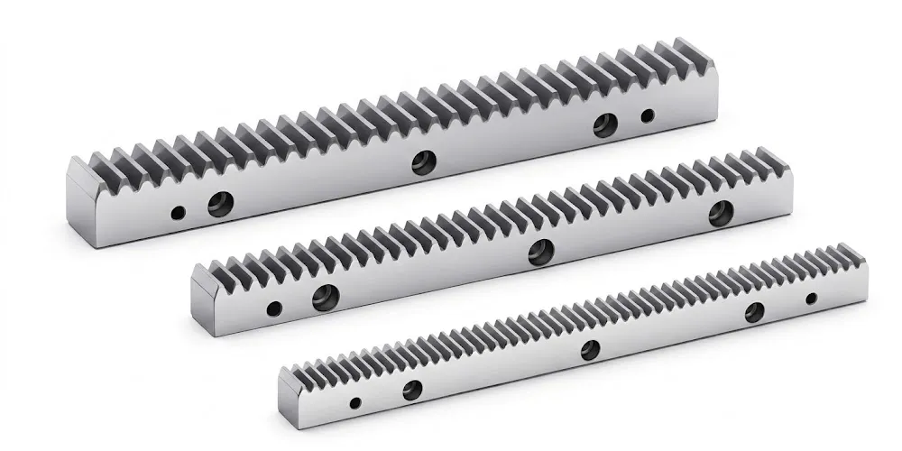
Cremalheira
For linear motion applications — CNC machine axes, gantry drives, automated rail systems, and lift mechanisms — the gear rack range provides the matching linear element to helical pinion gears. Rack modules are coordinated with the cylindrical helical gear module series, ensuring accurate pitch meshing without correction. Available in straight and helical rack forms, with lengths suitable for modular joining on long travel systems, the gear rack completes the helical rack and pinion drive where the precision and load capacity of a helical pinion gear is required in a linear motion system. Material options include carbon steel, alloy steel, and stainless steel grades for clean-room or corrosive environment applications.
Sobre a Unidade de Fabricação
With more than ten years of hands-on experience in precision mechanical transmission manufacturing, we operate a vertically integrated production site that covers the complete range of industrial drive components. Our product scope includes agricultural gearboxes, worm gear reducers, planetary gear drives, power take-off shafts, hydraulic cylinders, gears, chains, and motors — providing customers across multiple sectors with technically capable, single-source procurement for complex multi-component assemblies.
The manufacturing facility is certified to ISO 9001:2015, with quality management applied from raw material intake through to final shipment inspection. We design and produce a comprehensive range of industrial and agricultural gearboxes and assemblies in materials that include ductile iron, cast iron, cast steel, precision cast steel, and cast aluminium. Standard and non-standard mechanical components — including gears, sprockets, worm gears, pulleys, worms, and shafts — are all produced in-house under the same quality system. This integrated approach ensures that dimensional and material quality control is maintained across every component in the drive system, rather than depending on a chain of subcontractors with differing quality standards.
The locomotive flank helical gear programme reflects the most demanding tier of our gear manufacturing capability, and the engineering rigour applied to rail-specification products flows through to every helical gear we produce across all sectors. Customers in Europe, North America, Australia, the Middle East, Southeast Asia, and South America have relied on this manufacturing base for both standard and fully engineered custom made helical gears. We are a factory, not a trading intermediary, which means every technical query is answered by the engineers and machinists responsible for producing the product.
Perguntas frequentes
The questions below address the most common technical and sourcing queries received from rail operators, gearbox OEMs, and maintenance teams evaluating precision helical gear replacements and new equipment specifications.
Editor: PXY