
Mining & Quarrying · Technical Reference
An engineering reference for drill rig designers, OEM procurement engineers, and maintenance specialists in open-pit blasthole drilling, geotechnical investigation, and quarry perforation operations across Australia, Canada, South Africa, the United States, and Europe.
The rotary head drive of a drill rig — whether a surface blasthole machine, a sonic drill, a reverse-circulation rig, or a geotechnical investigation unit — subjects its transmission to a category of loading that very few other mining drive applications impose: reverse impact. When a tricone bit or DTH hammer encounters a hard formation boundary, a buried boulder, or a change in rock competency, the rotational resistance of the drill string can reverse abruptly. The drive train decelerates, then the reaction of the rotating drill string mass attempts to back-drive the head through the reducer. The torque direction reverses within milliseconds, applying a load to the back-face of the gear teeth that may be significantly higher than the rated forward torque — particularly if the string inertia is large.
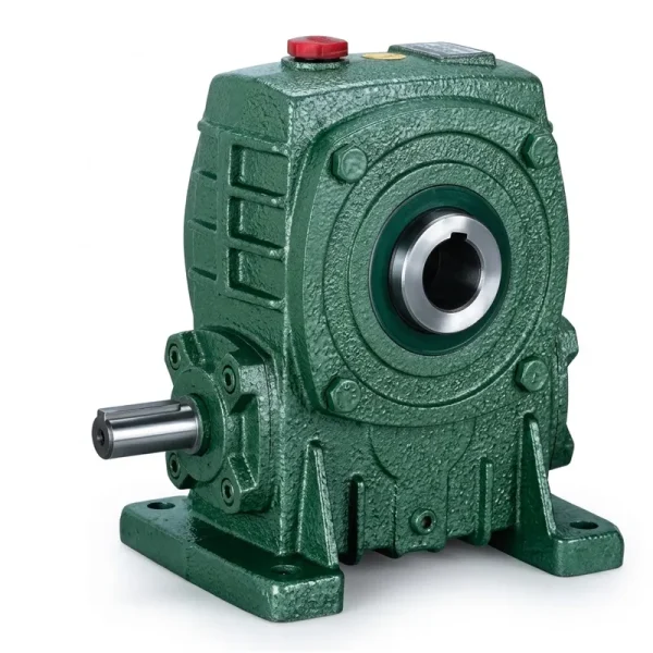
This loading mode is what distinguishes drill rig rotary head specification from most other single speed reducer applications. Standard catalogue selection based on forward rated torque and a moderate service factor is insufficient. The reducer must be evaluated for back-drive torque capacity, tooth-face compliance under load reversal, housing stiffness under reverse loading, and bearing axial capacity to handle the thrust reversal that accompanies direction change in a helical or worm gear mesh. This article covers each of these engineering requirements and identifies the EP-WPKA and EP-WPKS series as reference products for the mid-to-heavy end of the drill rig rotary head drive market.
The Mechanics of Reverse Impact in a Rotary Head Drive Train
In forward drilling, the rotary head motor accelerates the drill string to operating speed and maintains torque against the formation resistance. The motor current is relatively stable, the gear teeth carry load on their drive faces, and the bearing system handles a steady combination of radial (gear mesh separation force) and axial (worm gear thrust) loads. This is the condition for which the single speed reducer catalogue rating applies.
Reverse impact occurs in three distinct scenarios. The first is bit drop: when a drill breaks through a hard layer into a void or soft formation, the formation resistance drops abruptly, the string accelerates, and the motor — still commanding torque — overspeeds momentarily before the control system responds. The second is string stall: the bit jams in a crevice, the string torsional stiffness absorbs energy until the torsional spring-back releases it in the reverse direction at high angular velocity. The third is tool pullout: withdrawing a stuck drill string from a formation grip point releases elastic strain energy stored in the string as torsion, spinning the string in reverse at several times the forward drilling speed. All three scenarios impose reverse torque on the single speed gear reducer that may reach 1.5–3.0 times the rated forward torque, at angular velocities that engage the gear tooth back-faces with an impact rather than a gradual contact. Specifying a reducer that accounts for all three requires both a correct service factor and attention to the specific structural features that govern back-drive performance.

Manufacturing Structure — What Makes a Reducer Suitable for Reverse Impact
ஒரு single speed worm gear reducer intended for drill rig rotary head service differs from a standard catalogue unit in several structural details. The worm shaft is manufactured as a one-piece integral forging rather than a built-up assembly, ensuring that the shaft-to-worm joint does not relax under the cyclic torque reversals of drilling service. The worm thread is hobbed and then precision-ground on both flanks — both the drive flank (which carries forward drilling torque) and the coast flank (which carries reverse impact torque) — to the same surface finish and profile accuracy. In a standard low-duty reducer, only the drive flank is ground to close tolerances; in a drill rig unit, the coast flank must carry nearly equivalent load and must therefore be prepared to the same quality.
The worm wheel tooth ring is centrifugally cast in high-tin phosphor bronze for maximum uniformity of the alloy microstructure — porosity or inclusion concentrations in a sand-cast ring create stress-concentration sites that initiate fatigue cracks under the repeated load reversals of drill rig service. The housing is ribbed ductile iron, machined in a single chucking to ensure the worm shaft bore, worm wheel bore, and all mounting faces are precisely co-axial and perpendicular. Critically, the bearing selection for a drill rig reducer must account for the axial thrust reversal that accompanies torque reversal in a worm gear mesh: both input and output bearing sets must be specified as paired angular-contact or spherical roller bearings capable of carrying design thrust in both directions rather than the single-direction deep-groove bearings sufficient for unidirectional conveyor drives.
Material System for Reverse-Impact Drill Rig Service
Nickel-chromium-molybdenum alloy steel provides both the case hardness (HRC 60–62 after carburising and grinding) needed for worm flank contact fatigue life and the core toughness (core hardness HRC 32–38) needed to absorb the bending shock of reverse impact loading without brittle fracture. Both drive and coast flanks are ground to Ra 0.4 µm or better.
High-tin phosphor bronze (10% Sn, 1% Pb) centrifugally cast for dense, uniform microstructure. The tin content provides compressive yield strength adequate for the elevated contact stress of reverse-load engagement, and the lead addition improves the emergency dry-running tolerance that protects the wheel during the brief periods of mixed lubrication at cold start or after a long idle period — common on drill rigs that run intermittently between formation changes.
Ductile iron (minimum tensile strength 500 MPa, elongation 7%) provides the fracture toughness to survive repeated shock loading without crack initiation at stress concentrations — a property that grey cast iron lacks at equivalent wall thickness. External ribs increase torsional stiffness without adding mass, limiting the elastic deformation of the housing under reverse torque peaks that would otherwise cause misalignment between the worm and wheel during the transient.
Standard catalogue reducers use deep-groove ball bearings optimised for radial load with limited axial capacity in one direction. Drill rig service requires bidirectional axial load capacity: paired face-to-face angular-contact ball bearings (15°–25° contact angle) for lighter frame sizes, or spherical roller bearings with a floating/fixed arrangement for larger frames where the worm shaft thrust forces require higher axial dynamic capacity than ball bearings provide.
Drill rigs operate in environments with airborne formation dust (silica, coal, mineral particulate) that is highly abrasive to shaft seals. A V-ring pre-seal in front of a PTFE-lipped radial shaft seal provides two barriers against dust ingress: the V-ring excludes the bulk of the particulate, protecting the lip seal from the abrasion that shortens its service life to unacceptable intervals in single-seal arrangements used in standard catalogue reducers.
The external housing surface receives an epoxy primer (80 µm DFT) followed by an aliphatic polyurethane topcoat (60 µm DFT), selected for resistance to the diesel fuel, hydraulic oil mist, and alkaline or acid drilling flush water that covers most drill rig drive system surfaces in service. This coating system outlasts standard single-component alkyd paint by a factor of 3–5 in field service on drill rigs operating in Australian, South African, and North American mine sites.
Service Factor Guidelines for Drill Rig Rotary Head Reducer Selection
The table below provides service factor guidance for worm gear speed reducers used in drill rig rotary head applications. These factors are additive: the applicable factors for an installation are summed and applied to the motor rated power before entering the reducer torque-capacity table. The resulting corrected power is the figure used to select the reducer frame size and output torque rating from the single speed reducer product range.
| Loading Condition | Service Factor Addition | Typical Drill Application |
|---|---|---|
| Base — smooth, uniform, no shock | 1.00 | Not applicable for drill rigs |
| Moderate shock, 2–5 starts/hour | +0.25 | Geotechnical investigation, soft formation sonic drill |
| Heavy shock, >5 starts/hour | +0.50 | Open-pit blasthole rotary drilling, hard rock |
| Frequent torque reversal (bit drop or string stall) | +0.50 | All reverse-impact drill rig rotary head drives |
| Ambient temperature >40 °C | +0.25 per 10 °C above 40 °C | Surface rigs in Australia, Chile, South Africa desert sites |
| Ambient temperature <–10 °C (cold-start viscosity) | +0.25 | Canadian and Northern European drill rig winter operation |
| Non-horizontal mounting (oil distribution effect) | +0.10–0.25 | Angled drill mast, off-horizontal head rotation axis |
Recommended Products for Drill Rig Rotary Head Drives

Lubrication Specification for Reverse-Impact Drill Service
The lubricant in a drill rig rotary head worm gear reducer faces conditions that differ substantially from a fixed-installation conveyor reducer: the unit operates in multiple orientations (the drill mast angles from vertical to near-horizontal on some rigs), ambient temperatures swing from sub-zero at cold start in Canadian or Norwegian winter conditions to 50 °C surface ambient on Australian summer blast sites, and the cyclic torque reversals generate oil pressure spikes in the reducer sump that exceed the steady-state value calculated from forward-load conditions.
The appropriate lubricant specification for this service is a fully synthetic PAO ISO VG 460 gear oil with extreme-pressure additives (AGMA EP rating) and confirmed tin-bronze compatibility (ASTM D130 copper corrosion test, 120 °C, 3 hours, maximum rating 2B). The PAO base stock provides a higher viscosity index than mineral oil — the oil maintains adequate film thickness across a wider temperature range without requiring a winter-grade reformulation for cold-start conditions on Canadian or Scandinavian sites. The extreme-pressure additive package protects both flanks of the worm tooth during the high-contact-stress engagement that occurs at each torque reversal, when the oil film has not yet re-established on the coast flank after the previous forward load cycle. Oil change interval for this specification in drill rig service is 1500–2000 hours, with quarterly oil sampling recommended to detect bronze particle generation (early warning of tooth wear progression) before it reaches a level requiring shutdown for wheel replacement.
Climate-Specific Considerations for Drill Rig Reducer Performance
At ambient temperatures below –20 °C, ISO VG 460 mineral oil becomes viscous enough to prevent adequate distribution within the reducer housing during the first minutes of operation. A drill rig that starts cold and immediately commands high rotary speed subjects the worm mesh to mixed-lubrication contact before the oil has reached operating temperature and viscosity. For Canadian and Nordic sites, the preferred solution is a pre-start oil heater (immersion heater in the sump, thermostatically controlled to maintain oil above 0 °C during standby) combined with a warm-up protocol of two to three minutes at minimum load before commanding full drilling torque. Alternatively, synthetic PAO ISO VG 220 provides adequate film thickness at –30 °C without requiring active heating on most mid-range frame sizes of the single speed worm reducer series.
On Australian Pilbara and Atacama or Kalahari drill sites where surface ambient temperatures exceed 45 °C and direct solar radiation adds a further 15–20 °C to the surface temperature of the reducer housing, thermal management of the worm speed reducer requires the same frame-size uplift approach used for other high-ambient mining drives: select one frame size larger than the minimum calculation indicates, specify synthetic PAO ISO VG 460, and consider a small screw-on heat-exchanger that circulates reducer oil through an air-blast cooler mounted in the rig’s air flow path. Confirming that the sump oil temperature stays below 90 °C at steady state — measured by a thermocouple during the commissioning run — validates the thermal adequacy of the selected configuration before extended operation commences.

Planned Maintenance and Failure Mode Awareness
The dominant failure modes for a single speed reducer in drill rig rotary head service, in order of field frequency, are: worm wheel tooth pitting or spalling (progressive contact fatigue on the bronze tooth faces), input shaft bearing failure (usually inner ring fatigue from the combined radial and axial loading of reverse-impact duty), and shaft seal failure leading to oil loss and subsequent oil-starvation damage. Understanding which failure mode has occurred is important for the post-mortem analysis that determines whether the root cause was incorrect service factor selection, inadequate lubrication, misalignment at installation, or exceeding the duty cycle.
Pitting on the drive flank only — the flank that carries forward drilling torque — indicates the reducer was correctly specified for reverse impact but is overloaded in forward drilling, suggesting the application’s motor power or string weight exceeds the assumed values in the selection calculation. Pitting on both flanks equally indicates the reducer is receiving shock loads in both directions at levels close to or exceeding its rated capacity; the appropriate response is to increase the service factor and uprate to a larger frame. Bearing failure on the output (worm wheel) side only, with intact input bearings, suggests that the drill shaft is applying an external radial load to the reducer output bore — usually caused by misalignment between the reducer bore and the drill head shaft centreline, which adds bending to the axial and radial loads the bearing was designed to carry. Quarterly oil sampling, monthly bearing temperature monitoring, and annual dimensional inspection of the worm wheel tooth profile are the minimum condition monitoring activities that maintain awareness of reducer health between planned maintenance interventions.
Manufacturing Background
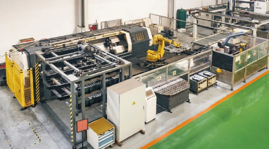
Our manufacturing facility has operated in mechanical power transmission engineering for more than ten years, developing a product range that covers agricultural gearboxes, worm gear reducers, planetary gear drives, power take-off shafts, hydraulic cylinders, precision gears, roller chains, and electric motors — all produced under ISO 9001:2015 quality management system certification. Structural components are manufactured in ductile iron, grey cast iron, cast steel, precision investment-cast steel, and aluminium alloy, with material grades selected to match the load, temperature, and service environment of each application. Gear teeth, worm shafts, sprockets, and output shafts are finished on multi-axis CNC hobbing, grinding, and turning centres to DIN and ISO dimensional standards. Customers specifying a complete drill rig rotary head drive system — reducer, motor, coupling hardware, and mounting provisions — can source all components through a single technically accountable manufacturing supplier rather than managing multi-vendor interface risks and parallel quality qualification processes.
பட்டறை



Compatible Drive Components
A complete drill rig rotary head drive station involves more than the reducer. The following component product lines are available from the same manufacturing source, enabling procurement teams to source a fully matched and documented drive system.


அடிக்கடி கேட்கப்படும் கேள்விகள்
பதிப்பாசிரியர்: PXY